May 6, 2011 - 1Directorate Science and Technology, AWE Aldermaston, Reading RG7 4PR, United Kingdom. 2Lawrence Livermore National Laboratory, ...
PRL 106, 185003 (2011)
PHYSICAL REVIEW LETTERS
week ending 6 MAY 2011
Measurements of Electron Transport in Foils Irradiated with a Picosecond Time Scale Laser Pulse C. R. D. Brown,1 D. J. Hoarty,1 S. F. James,1 D. Swatton,1 S. J. Hughes,1 J. W. Morton,1 T. M. Guymer,1 M. P. Hill,1 D. A. Chapman,1 J. E. Andrew,1 A. J. Comley,1 R. Shepherd,2 J. Dunn,2 H. Chen,2 M. Schneider,2 G. Brown,2 P. Beiersdorfer,2 and J. Emig2 1
Directorate Science and Technology, AWE Aldermaston, Reading RG7 4PR, United Kingdom Lawrence Livermore National Laboratory, 7000 East Avenue, Livermore, California 94550, USA (Received 27 November 2009; revised manuscript received 19 November 2010; published 6 May 2011) 2
The heating of solid foils by a picosecond time scale laser pulse has been studied by using x-ray emission spectroscopy. The target material was plastic foil with a buried layer of a spectroscopic tracer material. The laser pulse length was either 0.5 or 2 ps, which resulted in a laser irradiance that varied over the range 1016 –1019 W=cm2 . Time-resolved measurements of the buried layer emission spectra using an ultrafast x-ray streak camera were used to infer the density and temperature conditions as a function of laser parameters and depth of the buried layer. Comparison of the data to different models of electron transport showed that they are consistent with a model of electron transport that predicts the bulk of the target heating is due to return currents. DOI: 10.1103/PhysRevLett.106.185003
PACS numbers: 52.50.Jm, 52.25.Jm, 52.65.Rr, 52.70.La
Short pulse lasers have growing applications in micronscale manufacture, high energy radiography, particle beam physics, x-ray lasers, and inertial fusion energy schemes and in the study of plasmas at extremes of temperature and density relevant to stellar interiors [1,2]. Though new, highly energetic, short pulse laser facilities are being planned representing billions of dollars of investment [3], the fundamental issue of how solid material is heated by short pulse lasers is still poorly understood. Experiments on short pulse laser heating using targets with thin tracer layers buried in plastic foils have been carried out by a number of groups to investigate the properties of plasmas at high temperature [4,5] in a similar irradiance range to the data presented in this Letter. These data were interpreted by using radiation-hydrodynamics simulations and heat transport modeling using a flux-limited diffusion model or a combination of thermal diffusion and collisional heating using electron ranges based on BetheBloch formulas [6]. Experiments at irradiances (1019 –1020 W=cm2 ) similar to, or slightly above, the upper range of irradiance in the present experiments investigated heat transport by using tracer layers buried deeper into plastic foils [7,8] using infrared (1:06 �m wavelength) light and deduced heating to tens of microns from the spectroscopic tracer layer emission. The electron transport in these cases was modeled by using hybrid particle-in-cell codes where the electron transport is by a relativistic electron beam moving in a plasma background modeled as a fluid. In these experiments [7,8] an infrared short pulse beam without prepulse mitigation was used. In the following Letter, the effect a prepulse has on the electron transport is clearly demonstrated experimentally. This Letter reports a study of the heating of solid targets by a short pulse laser over a wide irradiance range of 0031-9007=11=106(18)=185003(4)
1016 –1019 W=cm2 . The laser used was the optical parametric chirped pulse amplification High-Energy Laser Embodying Neodymium system [9] operating at both 1:06 �m wavelength and in the second harmonic (green 0:53 �m) to mitigate the effect of any prepulse on the beam, thereby removing a significant uncertainty in the data interpretation. The target heating was diagnosed by emission spectroscopy which allowed the temperature and density at the buried layer position to be inferred. In novel measurements using two tracer layers buried at different depths in plastic, it has been conclusively demonstrated experimentally that heat is not transported into the target by thermal diffusion even at the lower intensities in the range studied. In experiments to measure peak temperature as a function of depth, the observed profiles cannot be accounted for by thermal conduction or by a forward propagating beam of electrons heating the target collisionally. Further experiments combining short and long pulse beams in heating measurements provide evidence that electron refluxing [10] from an electrostatic sheath field set up by relativistic electrons leaving the target cannot be invoked to explain the experimental results. However, the experiments are consistent with predictions of a twodimensional hybrid Monte Carlo electron transport model, THOR [11]. The conversion of 1:06 �m (infrared) light to the second harmonic (green), achieved by using a type I KDP (potassium dihydrogen phosphate) crystal, is strongly intensitydependent so the relatively low intensity prepulse was not converted. Any unconverted light was rejected at four mirrors coated to reflect green but not infrared light and positioned between the KDP crystal and the target, resulting in a calculated pulse contrast of 1010 . The conversion efficiency to green light was typically between 50% and
185003-1
Published by the American Physical Society
PRL 106, 185003 (2011)
PHYSICAL REVIEW LETTERS
60%. The intensity of the green beam on target was varied from 1016 to 1019 W=cm2 in either a 0.5 or a 2 ps FWHM pulse with an energy variation from 10 up to 40 J. The laser focal spot was varied between 20 and 100 �m, and the polarization was changed from S to P by tilting the target away from the focussing parabola by 30�. In addition some shots were carried out with the bare infrared beam and with the infrared beam reflected from a plasma mirror. In this case the prepulse passes through the plasma mirror, whereas the main beam is reflected once the leading edge of the pulse forms a plasma at the mirror surface with a measured reflectivity of 55%. In the two tracer layer experiments, the target was made from 1 �m plastic (parylene-N), a 0:05 �m layer of aluminum, a layer of polypropylene plastic, which was varied from 1.5 to 15 �m, a 0:05 �m layer of silicon, and finally a 1 �m layer of parylene-N plastic. For most measurements, the laser irradiated the target on the side closest to the aluminum layer. In other experiments, a parylene-N plastic foil with a single tracer layer of 0:15 �m aluminum was used to establish how the peak temperature in the foil varied with depth. The thickness of the plastic between the laser and the tracer layer varied systematically from shot to shot between 0.5 and 20 �m. Laser irradiance, pulse length, polarization, and wavelength were varied in the study. Comparisons using the bare infrared beam and prepulse mitigation as described above were included. Also experiments using a combination of short pulse and long pulse irradiance were performed where the plastic between the tracer layer and the rear surface was increased to 12 �m to create an ablator layer, and the plastic thickness between the tracer layer and front surface was either 2 or 4 �m thick. The rear surface was irradiated with a square laser pulse, typically 200 J, 700 ps (FWHM), 0:53 �m wavelength, with a 100 ps rising edge, a 200 ps falling edge, and a 250 �m diameter focal spot. The front surface was irradiated with a 0.5 ps FWHM green wavelength laser pulse as in the earlier experiments. The delay between the rising edge of the long pulse beam and the short pulse beam was varied between 250 and 600 ps in the study. In all the experiments, the sample foils were mounted over a hole in a plastic washer of 2 mm outer diameter and an inner diameter of 0.8 mm. The samples were either continuous layers or 50 �m diameter microdots. The diagnostics used to measure the target emission included an ultrafast x-ray streak camera, with a Photonis P860X tube coupled to a conical CsAP focussing crystal. The photocathode material used was solid potassium iodide (0:1 �m KI=0:02 �m Al=1 �m plastic). The time resolution of this instrument was determined by the photocathode response with the focussing of the streak tube across the photocathode obviating any effect due to the cathode width. This gave a temporal resolution of 1 ps, which was characterized offline. The images were corrected to account for temporal dispersion and distortion due to the streak camera tube. The spectral range covered the n ¼ 1–3 transitions in He-like and H-like aluminum and n ¼ 1–2 transitions in
week ending 6 MAY 2011
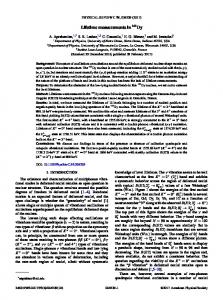
He-like and H-like silicon. Other diagnostics used were time-integrating crystal spectrometers recording onto x-ray film, and x-ray pinhole cameras to measure the focal spot. The emission spectra from the tracer layers were compared to predicted spectra from the time-dependent collisionalradiative models FLY [12] and FLYCHK [13]. The temperature was inferred from the ratio of the Ly� =He� emission intensities, and the density was inferred from the line shapes of these emission lines as reported elsewhere [14]. Temperatures lower than 200 eV were not recorded, in part because of the low dynamic range of the ultrafast camera. The time-integrated data intensity ratios and linewidths were found to agree closely with those recorded with the streak camera, indicating that the rapid falloff in temperature observed on the streak camera was not a diagnostic artifact. Figure 1 shows a plot of temperature versus depth for the 0.5 ps FWHM pulse-length experiments. The data are taken from both time-resolved and time-integrated measurements. In the case of the bare infrared beam, the linewidths seen in the emission spectrum indicate a preexpansion of the target foil ahead of the main chirped pulse amplification pulse, with the sample layer an order of magnitude less dense than in the cases with prepulse mitigation. The heating profiles show that, apart from very close to the front of the target, the temperature is slowly varying with depth before falling rapidly over the space of a micron to below the detection threshold. The depth of the heating increases with increasing irradiance and with P polarization relative to S polarization. The data from the bare infrared beam show poor coupling of the laser energy to heat the target. This is clearly seen by comparing the bare infrared beam data and infrared data when using a plasma mirror, where the target heating was
FIG. 1 (color). The peak temperature as a function of depth for various laser parameters. The results are for (1) a P-polarized, bare infrared beam, 1019 W=cm2 ; (2) S, 2!, 6 � 1017 W=cm2 ; (3) P, 2!, 6 � 1017 W=cm2 ; (4) S, 2!, 1019 W=cm2 ; (5) P, 1! with a plasma mirror, 6 � 1018 W=cm2 ; (6) P, 2!, 1019 W=cm2 ; and (7) data from germanium (blue) and titanium (red) layers.
185003-2
PRL 106, 185003 (2011)
PHYSICAL REVIEW LETTERS
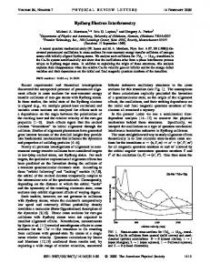
to the largest depth of all the cases investigated. Figure 2 shows a representative sample of the streaked data from the two tracer layer experiments. In all cases the emission from the silicon tracer layer begins simultaneously with the emission from the aluminum. The differences in emission from the two layers as the laser parameters are changed are in agreement with the findings of the peak temperature versus depth measurements shown in Fig. 1. The data were compared to a range of electron transport models. The two-dimensional radiation-hydrodynamics model NYM [15,16] was used with a two-temperature electron distribution, where the higher temperature electrons can free-stream into the target with the subsequent collisional heating based on the Bethe-Bloch formalism [6] assuming a Maxwellian electron distribution, with an electron temperature (Thot ) given by the scaling suggested by Beg et al. [17]. The lower temperature distribution was due to energy dumped at the critical surface and transported into the target as either a flux-limited diffusive wave or alternatively as a nonlocal thermal conduction wave following the method of Schurtz et al. [18]. The total fraction of laser energy absorbed was consistent with published measurements [19]. Although this model was expected to be invalid above 1018 W=cm2 , comparison to experiment shows conclusively that it is invalid even down to
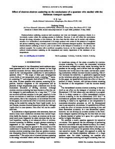
irradiances between 1016 and 1017 W=cm2 , where hot electron production is much less efficient. This was shown in the incorrect prediction of both a significant transit time (up to 50 ps) between layers and the profile of the peak temperature with depth. This differs from previous work at similar irradiance but using a longer pulse length [20]. Modeling of collisional heating due to only the forward fast electron current gave a peak temperature much lower than observed (see Fig. 3). Electron refluxing was considered where electrons reflect back and forth between a sheath potential, produced at the rear surface by the acceleration of relativistic electrons, and the critical surface. In the experiments combining long and short pulses, the long pulse beam ablated the rear target surface, preventing the formation of a sheath field, while the short pulse laser heated the target from the front side as previously. Aluminum tracer layers buried up to 4 �m in the plastic foil recorded the same temperature as in the experiments where the short pulse laser alone was used to heat the target, implying that electron refluxing is not a significant heating mechanism in these experiments. Finally, a twodimensional hybrid Monte Carlo electron transport model THOR was used to predict the temperature profile. This model of electron transport is based on that postulated by Bell and Davies [19,21] where a forward-going fast electron current Jh is balanced by a counterpropagating ‘‘cold’’ return current Jc drawn from the background plasma as shown in Eq. (1): Jc ¼ �Jh ¼ �E:
FIG. 2. X-ray emission spectra measured with an ultrafast streak camera with time going from left to right. The data shown are representative examples from experiments at different irradiance and polarization. These are (a) S-polarized 1019 W=cm2 , 4 �m layer separation; (b) P-polarized 1019 W=cm2 , 15 �m layer separation; (c) P-polarized 5 � 1017 W=cm2 separation 10 �m; and (d) P-polarized 1:4 � 1016 W=cm2 , separation 4 �m.
week ending 6 MAY 2011
(1)
FIG. 3 (color). Comparison of the THOR2 model predictions and experimental results. The black data points are aluminum P 2! 1019 W=cm2 and at 6 � 1018 W=cm2 using infrared light and a plasma mirror at P polarization. The red and blue data points are from titanium and germanium buried layers, respectively. The solid blue and red lines are the predictions of THOR2 for Th ¼ 300 keV, 35% absorption 35� and 25� divergences, respectively. The dotted line is the 25� case with the magnetic field off. The solid black line is the collisional heating due only to the forward current.
185003-3
PRL 106, 185003 (2011)
PHYSICAL REVIEW LETTERS
The return current is considered as resistive, and the electric field E required to draw the neutralizing current can be inferred from the conductivity �. The magnetic field B is then derived from Faraday as in Eq. (2): � � J �B ¼r�E¼r h : (2) � �t The fast electrons were transported by using a Monte Carlo algorithm based on Ref. [22]. The kinetic forward-going electrons lose energy via collisions with the background plasma fluid and under the action of the electric field, reducing their range as they propagate through the target. Energy lost from the kinetic electrons is used to heat the background. The high temperatures seen in the experiments are due predominantly to Ohmic heating Jc2 =� by the return current. The hot electron current was injected with a 300 keV temperature Maxwellian distribution—consistent with published scaling [23]. Sensitivity studies of the values of the electron temperature and absorption fraction into hot electrons showed that values used in Fig. 3 represent the best agreement with both the experiment and earlier experimental studies of these parameters by other groups [23,24]. The injection of hot electrons was further parameterized with a divergence angle, in this case a half angle of 25�. The energy of the electron current was chosen to match the absorbed fraction of the laser energy. In other respects, the injection parameters matched the known temporal and spatial characteristics of the laser spot. Comparisons of the THOR2 predictions to a representative sample of the experimental data are shown in Fig. 3. The model reproduces the near instantaneous heating observed in the experiments and is in reasonable agreement with the overall peak temperature profile as a function of depth in the target. The rapid fall in temperature over about a micron seen in the experiments was not reproduced in the simulations, but a more gradual fall was seen with the point of inflection dependent strongly on the choice of the divergence angle of the forward electron current. In the parameter study the divergence half angle was varied, and the closest agreement to experiment found for the divergence half angle of 25� , which is in reasonable agreement with the electron divergence inferred from other experiments [25,26] and theory [27]. The effect of changing the divergence half angle 25� –35� is shown in Fig. 3. The solid red line in Fig. 3 gives a reasonable agreement with the measured profile from the aluminum buried layer data. The heating profile is also influenced by the induced magnetic field, which has a collimating effect on the forward propagating electrons. The magnitude of the effect can be seen by comparing the red and the dotted curves in Fig. 3. The dotted curve has the same parameters as the red curve but with the magnetic field switched off. The sensitivity to the conduction models
week ending 6 MAY 2011
in THOR can be found in Ref. [11]. Despite the differences at large depths, overall THOR reproduces aspects of the target heating reasonably well. In summary, these experiments clearly demonstrate experimentally that models of target heating by short pulse laser driven electron transport invoking either thermal diffusion or alternatively uninhibited free-streaming electron transport are invalid over the whole irradiance range studied (1016 –1019 W=cm2 ) and that electron refluxing is not a significant heating mechanism in these cases. The effect of large scale-length plasma in front of the bulk solid due to the presence of a prepulse has been quantified in experiments with and without prepulse mitigation employed, a finding in agreement with recent calculations of fast ignition targets [28,29].
[1] M. Tabak et al., Phys. Plasmas 1, 1626 (1994). [2] S. J. Rose, Contemp. Phys. 45, 109 (2004). [3] Proceedings of the Sixth International Conference on Inertial Fusion Sciences and Applications, 2009, San Francisco, J. Phys. Conf. Series Vol. 244 (Institute of Physics, Bristol, 2010). [4] B. K. F. Young et al., Phys. Rev. E 58, 4929 (1998). [5] K. Eidmann et al., J. Quant. Spectrosc. Radiat. Transfer 81, 133 (2003). [6] R. J. Harrach and R. E. Kidder, Phys. Rev. A 23, 887 (1981). [7] J. A. Koch et al., Phys. Rev. E 65, 016410 (2001). [8] R. G. Evans et al., Appl. Phys. Lett. 86, 191505 (2005). [9] M. J. Norman et al., Appl. Opt. 41, 3497 (2002). [10] S. C. Wilks et al., Phys. Plasmas 8, 542 (2001). [11] D. A. Chapman et al., J. Phys. Conf. Ser. 244, 022031 (2010). [12] R. W. Lee and J. T. Larsen, J. Quant. Spectrosc. Radiat. Transfer 56, 535 (1996). [13] H.-K. Chung et al., High Energy Density Phys. 1, 3 (2005). [14] D. J. Hoarty et al., High Energy Density Phys. 3, 115 (2007). [15] P. D. Roberts et al., J. Phys. D 13, 1957 (1980). [16] D. J. Hoarty et al., Phys. Plasmas 6, 2171 (1999). [17] F. N. Beg et al., Phys. Plasmas 4, 447 (1997). [18] G. Schurtz et al., Phys. Plasmas 7, 4238 (2000). [19] A. R. Bell, J. R. Davies, and S. M. Guerin, Phys. Rev. E 58, 2471 (1998). [20] L. A. Gizzi et al., Laser Part. Beams 13, 511 (1995). [21] J. R. Davies et al., Phys. Rev. E 56, 7193 (1997). [22] M. E. Glinsky, Phys. Plasmas 2, 2796 (1995). [23] P. Gibbon, Short Pulse Laser Interactions with Matter: An Introduction (World Scientific, London, 2005). [24] Y. Ping et al., Phys. Rev. Lett. 100, 085004 (2008). [25] J. Fuchs et al., Phys. Rev. Lett. 91, 255002 (2003). [26] J. J. Santos et al., Phys. Plasmas 14, 103107 (2007). [27] M. Sherlock, Phys. Plasmas 16, 103101 (2009). [28] A. G. MacPhee et al., Phys. Rev. Lett. 104, 055002 (2010). [29] H.-B. Cai et al., Phys. Plasmas 17, 023106 (2010).
185003-4