sensors Article
Mechanical Coupling Error Suppression Technology for an Improved Decoupled Dual-Mass Micro-Gyroscope Bo Yang 1,2, *, Xingjun Wang 1,2 , Yunpeng Deng 1,2 and Di Hu 1,2 1 2
*
School of Instrument Science and Engineering, Southeast University, Nanjing 210096, China;
[email protected] (X.W.);
[email protected] (Y.D.);
[email protected] (D.H.) Key Laboratory of Micro-Inertial Instrument and Advanced Navigation Technology, Ministry of Education, Nanjing 210096, China Correspondence:
[email protected]; Tel.: +86-25-8379-3559
Academic Editor: Jörg F. Wagner Received: 10 January 2016; Accepted: 24 March 2016; Published: 8 April 2016
Abstract: This paper presents technology for the suppression of the mechanical coupling errors for an improved decoupled dual-mass micro-gyroscope (DDMG). The improved micro-gyroscope structure decreases the moment arm of the drive decoupled torque, which benefits the suppression of the non-ideal decoupled error. Quadrature correction electrodes are added to eliminate the residual quadrature error. The structure principle and the quadrature error suppression means of the DDMG are described in detail. ANSYS software is used to simulate the micro-gyroscope structure to verify the mechanical coupling error suppression effect. Compared with the former structure, simulation results demonstrate that the rotational displacements of the sense frame in the improved structure are substantially suppressed in the drive mode. The improved DDMG structure chip is fabricated by the deep dry silicon on glass (DDSOG) process. The feedback control circuits with quadrature control loops are designed to suppress the residual mechanical coupling error. Finally, the system performance of the DDMG prototype is tested. Compared with the former DDMG, the quadrature error in the improved dual-mass micro-gyroscope is decreased 9.66-fold, and the offset error is decreased 6.36-fold. Compared with the open loop sense, the feedback control circuits with quadrature control loop decrease the bias drift by 20.59-fold and the scale factor non-linearity by 2.81-fold in the ˘400˝ /s range. Keywords: decoupled dual-mass micro-gyroscope; quadrature error correction; mechanical coupling error; suppression technology
1. Introduction The silicon micro-gyroscope, which is a micro-inertial sensor based on micro-electro- mechanical system (MEMS) technology, has undergone 20 years of research and development [1–4]. The initial silicon micro-gyroscopes that mostly had a single mass cannot distinguish the Coriolis acceleration from the linear acceleration interference in the sensitive axis. To suppress the influence of acceleration or vibration, many researchers have studied the dual-mass silicon micro-gyroscope [5–7]. The differential sense capacitors in the dual-mass silicon micro-gyroscopes extract the anti-phase movement of a dual mass in the Coriolis acceleration and suppress the in-phase dual mass movement in the linear acceleration interference. The earlier silicon micro-gyroscopes had coupling structures between the drive mechanism and sense mechanism, which easily led to mechanical coupling between the two modes [8,9]. In [8], the inherent nonlinearity of the parallel plate actuators along the drive and sense axis directions was adopted to tune out the mechanical coupling error resulting from non-ideal stiffness
Sensors 2016, 16, 503; doi:10.3390/s16040503
www.mdpi.com/journal/sensors
Sensors Sensors2016, 2016,16, 16, 503 503
2 of 17 of17 17
on eight pairs of compensation electrodes to actively compensate the quadrature bias. elements. Anothermany previous study [9] gyroscopes capitalized on eight pairs compensation electrodes actively Simultaneously, decoupled insulated theof drive mechanism from to the sense compensate the quadrature bias. Simultaneously, many decoupled gyroscopes insulated the drive mechanism to reduce the mechanical coupling error [10–12]. In [10] two sets of decoupled beams mechanism from the sensewere mechanism the mechanical coupling error [10–12]. In [10] two sets and comb mechanisms utilizedtotoreduce decouple the drive movement from the sense movement. of decoupled beams and comb mechanisms were utilized to decouple the drive movement from the Similarly, the drive movement in [11] was segregated from the sense movement by three decoupled sense movement. Similarly, the drive movement in [11] was segregated from the sense movement by frames with several decoupled beams. Traditional decoupled frames were simplified as shuttles three severalthe decoupled beams. Traditional frames were simplified with decoupled decoupled frames beams with to separate drive movement from sensedecoupled movement [12]. However, given as shuttles with decoupled beams to separate the drive movement from sense movement [12].direction However, the difficulty in achieving ideal decoupling beams (the stiffness along the decoupling is given the difficulty in achieving ideal decoupling beams (the stiffness along the decoupling direction is almost zero, whereas the stiffness in the direction perpendicular to the decoupling direction is almost zero, the stiffnessperformance in the direction perpendicular to the decoupling direction infinite), infinite), thewhereas ideal decoupling was almost impossible to implement. Theisnon-ideal the ideal decoupling performance was almost impossible to implement. The non-ideal decoupling that decoupling that existed in most decoupled micro-gyroscopes would cause translational movement existed in most errors decoupled would cause translational movement displacement displacement and micro-gyroscopes rotational displacement errors. These non-ideal decoupled errorserrors were and rotational displacement errors. These non-ideal decoupled errors were sometimes even larger sometimes even larger than the other mechanical coupling errors. Simulation results in [13] than the other mechanical coupling errors. Simulation results in [13] confirmed that the maximum confirmed that the maximum rotation error displacement of the sense frame derived from the rotation error displacement of the sense frame derived from thein non-ideal reached 2.7% of non-ideal decoupling reached 2.7% of the drive displacement the drivedecoupling mode. the drive displacement in the drive mode. The present paper reports a mechanical coupling error suppression technology for an The present paper dual-mass reports a mechanical coupling(DDMG). error suppression technology for decreases an improved improved decoupled micro-gyroscope The improved design the decoupled dual-mass micro-gyroscope (DDMG). The improved design decreases the moment arm moment arm of the drive decoupled torque, which is beneficial for the suppression of the non-ideal of the drive error. decoupled torque, correction which is beneficial forare the added suppression of the non-ideal decoupled decoupled Quadrature electrodes to eliminate further the residual error. Quadrature electrodes are added to eliminateand further residual quadrature error. quadrature error.correction The structure principle, the simulation, the the experiment of the improved The structure principle, the simulation, and the experiment of the improved DDMG are presented. DDMG are presented. Section 2 gives an overview of the device description and the quadrature Section 2 gives an overview device description and the the quadrature error suppression of error suppression principleofofthe DDMG. Section 3 presents structure simulation and principle fabrication. DDMG. Section 3 presents the structure simulation and fabrication. Section 4 illustrates the quadrature Section 4 illustrates the quadrature correction and feedback control. Section 5 discusses the correction andConcluding feedback control. Section 5 discusses the experiments. remarks are finally experiments. remarks are finally summarized in Section Concluding 6. summarized in Section 6. 2. Device Description 2. Device Description 2.1. Device Device Principle Principle 2.1. Figure 11shows showsthe theimproved improvedDDMG DDMGstructure structurescheme scheme[14]. [14].The Thestructural structuralparameters parametersunder under Figure standard atmospheric pressure are shown in Table 1. standard atmospheric pressure are shown in Table 1.
Figure Figure1.1. Improved ImprovedDDMG DDMGstructural structuralscheme. scheme.
Sensors 2016, 16, 503
18 of 17
Sensors 2016, 16, 503
3 of 17
Table 1. Simulation parameters. Parameter Value Parameter Value Table 1. Simulation parameters. Drive decoupled beam 617 × 10 Thickness h (µm) 60 Drive suspension beam 630 × 10 Single proof mass m (kg) 5.13 × 10⁻⁷ Parameter Value Parameter Value 400 Sense suspension beam 518 × 10 Drive mode Q-factor Qx Drive decoupled beam 617 ˆ 10 Thickness h (µm) 60 y 255 Sense decoupled beam 540 × 10 Sense mode Q-factor Q ´7 Drive suspension beam 630 ˆ 10 Single proof mass m (kg) 5.13 ˆ 10 Length × Width (µm) Suspension beam of frame 518 540 Single driveQ-factor stiffness Sense suspension beam ˆ 10× 10 Drive mode Qx kx (N/m) 400 205.6 Sense mode Q-factor Qy kox (N/m) 255 32.5 Sense decoupled beam ˆ 10× 10 Sense coupling suspension beam540 665 Drive coupling stiffness Length ˆ Width (µm) Suspension beam of frame 540 ˆ 10 Single drive stiffness kx (N/m) 205.6 Drive coupling suspension beam 648 × 10 Single sense stiffness ky (N/m) Sense coupling suspension beam 665 ˆ 10 Drive coupling stiffness kox (N/m) 32.5 247.4 Single sense stiffness ky (N/m) Drive coupling suspension beam 648 375 ˆ 10× 10 Lever support beam Sense coupling stiffness koy (N/m) 247.4 9.1 Lever support beam
375 ˆ 10
Sense coupling stiffness koy (N/m)
9.1
Utilizing the kinematic coupling of the drive coupling suspension beams, two proof masses Utilizing the kinematic coupling of the drivewith coupling suspension beams, proof masses realize realize the in-phase and anti-phase resonance the same frequency in two the drive direction. The the in-phase and anti-phase resonance with the same frequency in the drive direction. The resonant resonant frequencies in the drive direction can be calibrated by adjusting the stiffness of the drive frequencies the drive direction can be calibrated by adjusting the suspension stiffness of the driveSimilarly, suspensiona suspension in beam, drive decoupled beam, and drive coupling beams. beam, drive decoupled beam, andtodrive coupling suspension beams. Similarly, a complex lever complex lever system that is used achieve the kinematic coupling in the sense direction consists system that is used to achieve the kinematic coupling in the sense direction consists of the coupling of the coupling crossbeams, sense coupling suspension beams, and lever supporting beams, which crossbeams, sense coupling suspension beams, and leverproof supporting which the in-phase ensure the in-phase and anti-phase resonance of two massesbeams, with the sameensure frequencies in the and anti-phase of twofrequencies proof masses the same by frequencies thestiffness sense direction. The sense direction.resonance The resonant canwith be adjusted changinginthe of the sense resonant frequencies can be adjusted by changing the stiffness of the sense suspension beam, sense suspension beam, sense decoupled beam, and complex lever system. The frequency difference decoupled beam, and complex lever system. between in-phase mode and between in-phase mode and anti-phase modeThe canfrequency be added difference by increasing the coupling rigidity. The anti-phase mode can be added by increasing the coupling rigidity. The increase in the frequency increase in the frequency difference reduces mode coupling between the in-phase mode and difference mode coupling betweenare the beneficial in-phase mode and anti-phase mode. High modal anti-phasereduces mode. the High modal frequencies for suppressing shock and vibration. frequencies are beneficial for suppressing shock and vibration. However, mechanicalTherefore, sensitivitythe is However, mechanical sensitivity is decreased because of the large modal frequencies. decreased because of the large modal frequencies. Therefore, the modal distribution should consider a modal distribution should consider a compromise among the mode coupling, mechanical compromise among the mode coupling, mechanical sensitivity, andsupporting suppression of shock vibration. sensitivity, and suppression of shock and vibration. The lever beams canand suppress the The suppress the arcthat locus the end of the lever and ensure that the arc lever locus supporting at the end beams of thecan lever and ensure theat connecting point between the coupling connecting between the coupling crossbeam coupling suspension has adirection, straight crossbeam point and sense coupling suspension beam and has asense straight trajectory along beam the sense trajectory alongtothe sense the direction, which is used to remove the rotational motion of the proof which is used remove rotational motion error of the proof mass in the senseerror mode.The sense mass in the sense mode.The sense frame and drive decoupled beam are optimized to suppress frame and drive decoupled beam are optimized to suppress the mechanical coupling error in the the mechanical coupling error in the improved simplified model of the in the2 improved DDMG. The simplified model of DDMG. the senseThe frame in the drive mode is sense shownframe in Figure drive mode is shown in Figure is 2 [14]. The coupling crossbeam is simplified as a supporting point. The [14]. The coupling crossbeam simplified as a supporting point. The connecting point between the connecting point between the drive decoupled beam and the sense frame is moved to the bottom of drive decoupled beam and the sense frame is moved to the bottom of the improved sense frame, the improved sense is utilized to of reduce the moment armtorque of the drive decoupledremove torque which is utilized toframe, reducewhich the moment arm the drive decoupled and ultimately and ultimately remove the drive decoupled torque. the drive decoupled torque.
(A)
(B)
Figure 2. Simplified model of sense frame in the drive mode. (A) The original sense frame; (B) The Figure 2. Simplified model of sense frame in the drive mode. (A) The original sense frame; (B) The improvedsense senseframe. frame. improved
The force model of the sense frame in the drive mode shown in Figure 3 is set up to analyze The force model of the sense frame in the drive mode shown in Figure 3 is set up to analyze motion characteristics. The drive decoupled beam is simplified as a spring kddx with an equivalent motion characteristics. The drive decoupled beam is simplified as a spring kddx with an equivalent rigid moment arm l1. δ is the displacement of translational movement. θ is the rotational rigid moment arm l1 . δ is the displacement of translational movement. θ is the rotational displacement. displacement. ksx and kscx are the stiffness of sense suspension beam and sense coupling suspension ksx and kscx are the stiffness of sense suspension beam and sense coupling suspension beam along the
Fo (l1 l2 ) 2ksx[δ (2l l2 )θ](2l l2 ) 2kscx (δ l2θ)l2
(2)
Solving these equations, then: Sensors 2016, 16, 503
δ
[(2l l1 )(2l l2 ) 2l22 ]ksx l1l2 kscx Fo 8l 2 kscx ksx
4 of 17 (3)
l1k scx (l1 rotational 2l )k sx drive direction, respectively. ksθ and are the and θ kscθ Fo stiffness of sense suspension beam (4) 2 8l k scx k sx sense coupling suspension beam, respectively.
kscx k sc
ksc l2
2l
ksx
kscx l1
k s
ksx
L
k s
kddx
Figure 3. Simplified force model of improved sense frame in the x-axis direction. Figure 3. Simplified force model of improved sense frame in the x-axis direction.
Suppose θ == 0 no matter how the drive force Fo changes, then: The balance equations are:
2lk sx Fo “ 2k scx pδ ´ lk2 scx θq `k2k rδ ` p2l ´ l2 qθs sx sx l1
(5)
(1)
Therefore, the rotational by2koptimizing the drive decoupled (2) Fo pl1 ´displacement l2 q “ 2k sx rδ `can p2l be ´ l2suppressed qθsp2l ´ l2 q ´ scx pδ ´ l2 θql2 beam, sense coupling suspension beam, and sense suspension beam to satisfy Equation (5). When Solvingfor these equations, then: the conditions Equation (5) are met, then: δ“
rp2l ´ l1 qp2l ´ l2Fqo ` 2l22 sk sx ` l1 l2 k scx δ Fo 2(k8lscx2 kscxk sxk sx ) l1 k scx 2lk` plk1sx´ 2lqk sx F θ“ o l2 8l 2scx k k2
(k scx scx ksx )sx
(6) (3) (7) (4)
Suppose θ == 0 no matter how the drive force Fo changes, then:
2.2. Quadrature Error Suppression
2lk sx l1 “ (5) k scx ` k sx The quadrature error correction scheme shown in Figure 4 is adopted to restrain further the quadrature error inthe therotational DDMG [15]. Four correction capacitors are given by the expressions: Therefore, displacement can be suppressed by optimizing the drive decoupled beam, sense coupling suspension beam, and sense suspension beam to satisfy Equation (5). When the conditions for Equation (5) are met, then: δ“
l2 “
Fo 2pk scx ` k sx q 2lk scx k sx pk scx ` k sx q2
(6)
(7)
Sensors 2016, 16, 503
5 of 17
Sensors 2016, 16, 503
20 of 17
2.2. Quadrature Error Suppression
The quadrature in Figure is xadopted to restrain ε ( L error x)h correctionε 0scheme ε ( L4 )h ε ( L further x)h the ( Lss x)shown h , Cq 2 nq , Cq 3 nq 0 ss , Cq 4 nq 0 ss Cq1 nq 0 ss quadrature errord inthe DDMG [15]. Four correction capacitors are given by the expressions: y d y d y d y ss
ss
ss
ss
ε0 pLss ` xqh ε0 pLss ´ xqh ε0 pLof ` xqh ε0 pLss ´ xqh ss the where C nq is«the combs, h is nq number of combs, , Cq2 «Lnssqis the overlapping , Cq3 «length nq , Cq4 « nqthe thickness of the q1 d ´ y d ` y d ` y dss ´ ss ss combs, dss is the comb gap, and x andssy are the displacements along the X and Y ydirections, respectively. When the bias voltage V and feedback correction uq are applied on the quadrature where nq is the number of combs, Lss is the overlapping length of the combs, h is the thickness of the correction electrode, the stiffness matrix of static electric force is: combs, dss is the comb gap, and x and y are the displacements along the X and Y directions, respectively. When the bias voltage V and feedback onq the quadrature correction electrode, 4nq ε 0 hVu correction uq are applied 0 2 the stiffness matrix of static electric force is: d ss fi K q » (8) 4n ε 2 q 0 hVuq 2 4nq ε 0 hVu 0 q 4nq ε 0 hL 2ss (V uq ) d ss fl Kq « – 4n 2ε hVu (8) 4nq ε0 hLss pV3 2 `u2 q
dqss 02
q
d ss
q
d3ss
dss
where the non-diagonal item stiffness is used to remove the stiffness of quadrature error, and the where the non-diagonal item stiffness is used to remove the stiffness of quadrature error, and the diagonal item will decrease the sense mode frequency. diagonal item will decrease the sense mode frequency.
V+uq
Cq1
Proof mass
Cq2 Quadrature correction electrode
Sense axis Y Z
X Drive axis
Cq3
Cq4
dss V-uq
Figure 4. Quadrature error correction scheme.
3. Structure StructureSimulation Simulationand andFabrication Fabrication The working principle of DDMG was verified verified by by finite finite element element simulation. simulation. A finite element simulation model ANSYS software. Figure 5 illustrates thethe simulation results of the model isisset setup upwith withthe the ANSYS software. Figure 5 illustrates simulation results of drive and sense modes. The first which are the are mainthe interference modes, are in-phase the drive and sense modes. Thetwo firstmodes, two modes, which main interference modes, are modes in modes the drive anddirection illustrate and the acceleration sensitivity. The sensitivity. subsequent two in-phase inand thesense drivedirection and sense illustrate the acceleration The modes, which aremodes, main operational modes, are the anti-phase the drive modes and sense direction subsequent two which are main operational modes, modes are the in anti-phase in the drive and represent the Coriolis that the same resonance frequencies two sense direction and sensitivity. represent The the results Coriolisindicate sensitivity. The results indicate that theofsame masses are frequencies implemented in the drive mode, but not alsoonly in theinsense modemode, because kinematic resonance ofnot twoonly masses are implemented the drive butofalso in the coupling of the coupling beams. In the firstof fourth modes, the drive is isolated with sense mode because of kinematic coupling the coupling beams. Inmechanism the first fourth modes,fully the drive the sense mechanism, which demonstrates decoupling performance is achieved. Table 2 mechanism is isolated fully with the that senseexcellent mechanism, which demonstrates that excellent presents theperformance frequencies is of achieved. the first fifth modes of thethe DDMG. Apparently, the frequencies decoupling Table 2 presents frequencies of the first fifth modes of the useful third and fourth are insulated from third thoseand of the other interference modes.from In brief, DDMG. Apparently, themodes frequencies of the useful fourth modes are insulated thosethe of simulation results prove that the is feasible. the other interference modes. Instructure brief, theprinciple simulation results prove that the structure principle is To confirm the suppression effect of the mechanical coupling error in the improved DDSG, the feasible. displacements sense and driveeffect frames in the drive and modes. Figure 6 shows To confirmofthe suppression ofare theextracted mechanical coupling errorsense in the improved DDSG, the displacements of sense and drive frames are extracted in the drive and sense modes. Figure 6 shows the sense frame displacements in the anti-phase drive mode. Comparing the improved structure with the former structure, the rotational displacements in the improved structure are suppressed
Sensors 2016, 16, 503
6 of 17
the sense frame displacements in the anti-phase drive mode. Comparing the improved structure with the former structure, the rotational displacements in the improved structure are suppressed significantly by the optimum design. Table 3 shows the non-ideal decoupled displacements in the Sensors 2016, 16, 503 21 of 17 drive and sense modes (the measured points are shown in Figure 5). Obviously, the translational movement displacements in the design. improved arenon-ideal reduceddecoupled once in the drive mode (Points A significantly by the optimum Tablestructure 3 shows the displacements in the drive and sense modes (the measured points are shown in Figure 5). Obviously, the translational and C displacements along the x-axis). Furthermore, the rotational displacements in the improved movement displacements in the improved are reduced once theC drive mode (Points along A structure are substantially suppressed in thestructure drive mode (Points A in and displacements the and C displacements along the x-axis). Furthermore, the rotational displacements in the improved y-axis). This phenomenon is mainly due to the elimination of the drive coupling torque by decreasing structure are substantially suppressed in the drive mode (Points A and C displacements along the the moment arm. displacements the coupling sense mode areby observed. y-axis). ThisSimultaneously, phenomenon is non-ideal mainly duedecoupled to the elimination of the in drive torque The translational movement displacements of the drive frame in the improved structure are decreasing the moment arm. Simultaneously, non-ideal decoupled displacements in the sense modereduced are observed. The translational movement of the drive in the by 8.2 times in the sense mode (Point E and Gdisplacements displacements along theframe y-axis). Theimproved main reason is structure are reduced by 8.2 timesare in the sensetomode (Pointfurther E and Gthe displacements the y-axis). that suspension beams of the frame added increase rigidity of along the drive frame along The main Results reason is are thatconsistent suspension with beamstheoretical of the frameanalysis are addedand to increase further the the rigidity of of the the y-direction. demonstrate feasibility the drive frame along the y-direction. Results are consistent with theoretical analysis and optimization design. demonstrate the feasibility of the optimization design.
(A)
(B)
Figure 5. Cont.
Sensors 2016, 2016, 16, 16, 503 503 Sensors
of 17 17 227 of
(C) NODAL SOLUTION STEP=1 SUB =4 FREQ=3622.2 USUM (AVG) RSYS=0 DMX =961.502 SMX =961.502
B
C
A D
0
213.667 106.834
427.334 320.501
641.001 534.168
854.668 747.835
961.502
(D) Figure results. (A)(A) Drive mode withwith in-phase movement; (B) Sense modemode with Figure 5. 5. Modal Modalsimulation simulation results. Drive mode in-phase movement; (B) Sense in-phase movement; (C) Sense anti-phase movement; (D) Drive (D) mode withmode anti-phase with in-phase movement; (C)mode Sensewith mode with anti-phase movement; Drive with movement. anti-phase movement. Table Table 2. 2. First First fifth fifth modes modes of of the the DDMG. DDMG. Modal
Modal Frequency1 (Hz)
Frequency (Hz)
3157
1 31572 3463
2 3463
3 3588 3
3588
4 5 4 3622 6912 3622
5 6912
Sensors 2016, 16, 503
8 of 17
Sensors 2016, 16, 503
23 of 17
(A)
(B) Figure 6. Sense frame displacements in the anti-phase drive mode. (A) Improved structure; Figure 6. Sense frame displacements in the anti-phase drive mode. (A) Improved structure; (B) Former structure. (B) Former structure.
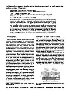
The rotational displacement of the sense frame in the anti-phase drive mode shown in Figure 7 The rotational displacement of the frame in the anti-phase drive shown in Figureof7 is is simulated to verify the influence of sense the support system stiffness on the mode rotational movement simulated to verify the influence of the support stiffness on the in rotational sense sense frame. The rotational displacement can be system suppressed completely the drivemovement decoupled of beam with The the width of 10displacement µm. However, changecompletely in the drive beam will alter frame. rotational canthe bewidth suppressed indecoupled the drive decoupled beamthe with equivalent rigid moment arm l 1 , so Equation (5) is not satisfied, that is, θ ≠ 0. Obviously, the stiffness the width of 10 µm. However, the width change in the drive decoupled beam will alter equivalent variation in the beam results in thethat emergence the rotational of rigid moment armdrive l1 , sodecoupled Equation (5) is not satisfied, is, θ ‰ 0.ofObviously, the displacement stiffness variation frame. Moreover, the rotational anrotational approximate linear relationship in sense the drive decoupled beam results in displacements the emergencehave of the displacement of sensewith frame. the widththe of rotational the drive decoupled beams. Moreover, displacements have an approximate linear relationship with the width of the
drive decoupled beams.
Sensors 2016, 16, 503
9 of 17
Sensors 2016, 16, 503 Sensors 2016, 16, Table 503
3. Non-ideal decoupled displacement in the drive and sense modes.
24 of 17 24 of 17
Table 3. Non-ideal decoupled displacement in the drive and sense modes. Table 3. Non-ideal decoupled displacement in theDecoupling drive and sense modes. Non-Ideal Displacement
Original Structure Improved Structure Non-Ideal Decoupling Displacement Non-Ideal Decoupling Displacement X-axis Y-axis ImprovedX-axis Y-axis Measurement Point Original Structure Structure Measurement Point Original Structure Improved Structure A 8.2355 ´25.697 ´4.18045 ´0.0142 X-axis Y-axis X-axis Y-axis X-axis Y-axis X-axis Y-axis B 3.568.2355 0.2235 −4.18045´4.2411 0.08024 A −25.697 −0.0142 A 8.2355 −25.697 −4.18045 −0.0142 Drive mode C 8.23553.56 26.164 −4.2411´4.18135 ´0.0143 B 0.2235 0.08024 B 3.56 0.2235 −4.2411 0.08024 Drive mode 0.08366 959.71 0.1766 −4.18135´960.14 Drive modeD C 8.2355 26.164 −0.0143 C 8.2355 26.164 −4.18135 −0.0143 E ´7.5332 ´12.260 −960.14 10.093 ´1.4942 D 959.71 0.1766 0.08366 D 959.71 0.1766 −960.14 0.08366 F 0.1549 ´12.112 10.093 ´0.11313 ´1.5029 E −7.5332 −12.260 −1.4942 E −7.5332 −12.260 10.093 −1.4942 Sense mode ´1.4942 G 7.8458 ´12.260 −0.11313´10.319 F 0.1549 −12.112 −1.5029 F 0.1549 −12.112 −0.11313 −1.5029 Sense mode 0.1603 ´900.11 −10.319´0.11848 ´909.05 Sense modeH G 7.8458 −12.260 −1.4942 G 7.8458 −12.260 −10.319 −1.4942 H 0.1603 −900.11 −0.11848 −909.05 H 0.1603 −900.11 −0.11848 −909.05 Measurement Point
Rotational displacement in piont A(um) Rotational displacement in piont A(um)
0.10 0.10
0.05 0.05
0.00 0.00
-0.05 -0.05
-0.10 -0.10
9.5 9.5
10.0 10.0
10.5 10.5
The width of drive decoupled beam(um) The width of drive decoupled beam(um)
Figure 7. 7. Rotational simulation sense frame in anti-phase Figure Rotationaldisplacement displacement simulation ofof sense frame in anti-phase drivedrive mode.mode. Figure 7. Rotational displacement simulation of sense frame in anti-phase drive mode.
A standard three-mask deep dry silicon on glass (DDSOG) process is adopted to fabricate the A standard three-mask deep drysilicon silicon on on glass glass (DDSOG) is adopted to fabricate the the A standard three-mask deep dry (DDSOG)process process is adopted to fabricate structure chip of the DDMG. Figure 8 shows the fabricated structure chip. We adopt a silicon wafer structure chip of the DDMG. Figure 8 shows the fabricated structure chip. We adopt a silicon wafer structure chip of thewith DDMG. 8 shows the fabricated structure chip.fabrication We adoptincludes a siliconthe wafer of of single crystal a 4” Figure diameter to fabricate the DDMG device. The ofcrystal single with crystal with a 4” diameter to fabricate the DDMG device. The fabrication includes the single a 4” diameter to fabricate the DDMG device. The fabrication includes the following following steps: the photoresist is overlaid on the silicon wafer. The first mask is used to define the following steps: the photoresist is overlaid on the silicon wafer. The first mask is used to define the steps: the photoresist is overlaid on the silicon wafer. The maskbyisthe used toreactive define the bonding area bonding area and expose the photoresist. The bonding area first is etched deep ion etching bonding area and expose the photoresist. The bonding area is etched by the deep reactive ion etching and(DRIE). expose photoresist. bonding area islayer etched by the deep reactivewire ionby etching (DRIE). A Athe Pyrex glass waferThe sputters a Cr/Ti/Au to establish the electrode the second (DRIE). A Pyrex glass wafer sputters a Cr/Ti/Au layer to establish the electrode wire by the second mask. Pyrex glass wafer sputters a Cr/Ti/Au layer to establish the electrode wire by the second mask. mask.
(A) (A)
(B) (B)
Figure 8. Picture of the structure chip of DDMG. (A) Overall structure chip; (B) Partial view of the Figure 8. Picture of the structure chip of DDMG. (A) Overall structure chip; (B) Partial view of the
Figure 8. Picture structure chip. of the structure chip of DDMG. (A) Overall structure chip; (B) Partial view of the structure chip. structure chip.
Sensors2016, 2016,16, 16,503 503 Sensors
25ofof1717 10
Subsequently, the silicon wafer and the Pyrex glass wafer are connected by the electrostatic Subsequently, the silicon wafer and the glass wafer electrostatic anodic anodic bonding process. The thickness ofPyrex the silicon waferare is connected decreased by bythe a wet etching process bonding process. TheFinally, thickness the silicon wafer bysilicon a wet etching process with KOH solution. theofthird mask is usedistodecreased release the structure by thewith DRIEKOH with solution. Finally, third8A mask is used release the silicon structure the µm DRIE 20:1 20:1 aspect ratio.the Figure shows the to overall structure of 8300 µm ×by5000 × with 60 µm. A aspect partial ratio. Figure 8A shows the overall structure 8300decoupled µm ˆ 5000beam µm ˆand 60 µm. A partialcorrection structure shown structure shown in Figure 8B includes theof drive quadrature combs. inThe Figure 8B includes the drive decoupled correction The fabricated fabricated mechanical structure has abeam comband gapquadrature of 4 µm and a width combs. of suspension beam of mechanical structure has a comb gap of 4 µm and a width of suspension beam of 10 µm. 10 µm. 4.4. Quadrature Quadrature Correction Correction and and Feedback Feedback Control Control The thethe quadrature correction and and feedback control is shown in Figure The circuits Thescheme schemeofof quadrature correction feedback control is shown in 9.Figure 9. The include the pre-amplifier, the carrier, the auto gain control (AGC) loop, the phase control loop, the circuits include the pre-amplifier, the carrier, the auto gain control (AGC) loop, the phase control feedback control loop, and the quadrature control loop. loop, the feedback control loop, and the quadrature control loop.
Figure 9. Scheme of the quadrature correction and feedback control circuits. Figure 9. Scheme of the quadrature correction and feedback control circuits.
The AGC loop and phase control loop constitute a closed-loop self-excitation drive circuit. The drive displacement signal is demodulated by the ring diode and self-excitation magnified by drive the pre-amplifier. The AGC loop and phase control loop constitute a closed-loop circuit. The The amplitude of the driveisdisplacement is extracted byand the magnified amplitude detector and LPF and drive displacement signal demodulatedsignal by the ring diode by the pre-amplifier. thenamplitude contrasted the reference voltage. The result of the comparator used to and adjust PI The of with the drive displacement signal is extracted by the amplitudeisdetector LPFthe and controller output. Wethe utilize the AGC to stabilize theofdrive displacement Thethe phase then contrasted with reference voltage. The result the comparator is amplitude. used to adjust PI control loop is designed to satisfy the phase condition of the entire self-excitation drive circuit and controller output. We utilize the AGC to stabilize the drive displacement amplitude. The phase control locksis the naturalto frequency the condition anti-phaseofdrive mode.self-excitation The total phase of and the locks entire loop designed satisfy the in phase the entire driveshift circuit self-excitation loop equals 2nπ (where n is an integer). quadrature error the natural frequency in the anti-phase drive mode. The total Compared phase shift with of thethe entire self-excitation correction by force balancing [16], the new stiffness cancellation method based on the quadrature loop equals 2nπ (where n is an integer). Compared with the quadrature error correction by force correction[16], comb adopted to suppress the method quadrature error. Thequadrature new quadrature control loop, balancing theisnew stiffness cancellation based on the correction comb is which consists of the amplifier anderror. filter, The demodulation, LPF, control and PI, loop, directly feeds back the DC adopted to suppress the quadrature new quadrature which consists of the signal to and correct thedemodulation, quadrature error, eliminates amplitude the amplifier filter, LPF,which and PI, directly the feeds back theand DCphase signalinfluence to correctofthe modulatederror, AC which signaleliminates in a force manner of and quadrature thebalancing amplitude correction and phase influence theimproves modulatedthe AC quadrature signal in a correction accuracy. The feedback control loop, which consists of the amplifier and filter,
Sensors 2016, 16, 503
11 of 17
Sensors 2016, 16, 503 Sensors 2016, 16, 503
26 of 17 26 of 17
force balancing correction manner and improves the quadrature correction accuracy. The feedback Sensors 2016, 16, 503 LPF, PI, and demodulation, feeds back the modulated AC signal to compensate 26 ofthe 17 demodulation, control loop, whichLPF, consists of demodulation, the amplifier feeds and filter, demodulation, PI,toand demodulation, demodulation, PI, and back the modulated ACLPF, signal compensate the input Coriolis signal. The feedback control loop implements the closed-loop control to suppress the input the Coriolis signal. control loop implements the closed-loop control tofeedback suppressthe the feedsdemodulation, back modulated AC signal to compensate thethe input Coriolis signal. The control LPF,scheme PI,The andfeedback demodulation, feeds back modulated signal to compensate offset error. The of the closed-loop quadrature correction AC control system is shown in offsetCoriolis error. the The scheme of the closed-loop quadrature correction control system is shown in loop implements closed-loop control to suppress the offset error. The scheme of the closed-loop input signal. The feedback control loop implements the closed-loop control to suppress the Figure 10. Ωqua is the equivalent angular velocity of the quadrature error. According to Equation (8), Figureerror. 10. Ωqua is the equivalent angular velocity of the 10. quadrature error. According to Equation (8), 2 offset The scheme of the closed-loop quadrature correction control system is shown in quadrature correction control system is shown in Figure Ω is the equivalent angular velocity kq is the stiffness coefficient and kq = 4nqԐ0hV/(dss my). my is thequa proof mass in the sense mode. FLPF(s) of k q is the stiffness coefficient and kq = 4nqԐ0hV/(dss2my). my is the proof mass in the sense mode. FLPF(s) Figure 10. Ω qua is the equivalent angular velocity of the quadrature error.control According (8), the quadrature error. According to Equation (8), kq quadrature is the stiffness coefficient and system kq =to 4nEquation hV/(d is low pass filter. The simplified closed-loop correction in2 my ). qisε0shown ss is low pass filter. The simplified closed-loop quadrature correction control system is shown in 2 q is the 11. stiffness coefficient and kq = 4n qԐ0hV/(dss my). my is the proof mass in the sense mode. FLPF(s) Figure my is kthe proof mass in the sense mode. FLPF (s) is low pass filter. The simplified closed-loop quadrature Figure 11. is lowcontrol pass filter. Theissimplified correction system shown inclosed-loop Figure 11. quadrature correction control system is shown in Figure 11.
2 Axd cos(d t ) 2 Axd cos(d t 2 ) 2 qua 2 Axd cos(d t ) qua 2
qua
1 s 2 ( y /1Qy ) s y2 s 2 ( y / Qy ) s y2 1 2 s ( y / Qy ) s y2
Ax cos(d t ) Ax cos(d t 2 ) 2 Ax cos(d t ) 2
kq kq kq
2cos(d t ) 2cos(d t 2 ) 2
K int2cos(d t ) FLPF ( s) 2 FLPF ( s ) K int K int
K ac K ac
FLPF ( s )
Kp KKSii Kp S
Kp KSi
K ac
Figure 10. Scheme of the closed-loopquadrature quadrature correction system. Figure 10. Scheme of the closed-loop correctioncontrol control system. Figure 10. Scheme of the closed-loop quadrature correction control system. Figure 10. Scheme of the closed-loop quadrature correction control system. U qua (t ) K K p Ki FLPF ( s ) G(s,d ) Kint Axd U qua (t ) K p si FLPF ( s ) qua G(s,d ) Kint Axd s qua U K qua (t ) Kp i FLPF ( s ) G(s,d ) Kint Axd s
qua
kq Kac / (2d ) kq Kac / (2d )
kq Kac / (2d ) correction control system. Figure 11. Simplified closed-loop Figure 11. Simplified closed-loopquadrature quadrature correction control system. Figure 11. Simplified closed-loop quadrature correction control system.
11. of Simplified closed-loop quadraturecorrection correction control control system. The transfer Figure function the closed-loop quadrature system is: The transfer function of the closed-loop quadrature controlsystem system The transfer function of the closed-loop quadraturecorrection correction control is:is:
G ( s, ω ) K A ω F ( s)( K K / s ) (9) d intA xxωd FLPF p p `i K {sq qua Gps, i d LPF psqpK H ( s ) 1 G ( s,ω ωdd qK ) Kint (9) (9) qua“ int Ax FLPF ( s )( K p K i / s ) k q K ac / 2 Hqua psq G ( s , ω ) K A ω F ( s )( K K / s ) 1 G ( s , ω ) K A F ( s )( K K / s ) k K / 2 int LPF p p p`i Kii{sqk q q ac d int intAxx x F dLPF LPF 1 ` Gps, ωddqK psqpK Kac {2 H ( s ) (9) jθ jθ qua G((ss, ω j)ωK ) ,Axand Qy )/s2 ω2y ) . According to the where G(s,ωd ) e jθG(s jωd ) 1e jG FLPF (Gs()(s)Kp1/ (Ks2 / s(ω ) ky /K e G(s jωd ) e´θjθG(s djωdd int ) , and G(s) 1/ (s2i (ωy2q/ Qacy )s ω2y ) . According to the where G(s,ωd )jθ 2 wheresimulation Gps, ωd q “parameters e Gps ´ jω q ` e jθ 4, Gps jωd q, and Gpsqis“simulated 1{ps ` pω y qs ` ωthe in dTable the `control system toy {Q optimize control y q. According jθ 2 2 G ( s ,ω ) e G ( s j ω ) e G ( s j ω ) G ( s ) 1/ ( s (ω / Q ) s ω ) simulation parameters in Table 4, the control system is simulated to optimize the control , and . According to the where d d d y y y to theperformance. simulation parameters in Table 4, the control systemcorrection is simulated tocircuits optimize the control The Bode diagram of closed-loop quadrature control is shown in performance. The Bode in diagram of closed-loop quadrature correction control circuits the is shown in simulation parameters Table 4, the control system is simulated to optimize control Figure 12.The Obviously, a good closed-loop quadrature correction control is control implemented. performance. Bode diagram of closed-loop quadrature correction circuits is shown in Figure 12. Obviously, a good closed-loop quadrature correction control control is implemented. performance. The Bode diagram of closed-loop quadrature correction circuits is shown in Figure 12. Obviously, a good closed-loop quadrature correction control is implemented. Bode Diagram The transfer function correction G ( s, ωdquadrature ) Kint Ax ωd FLPF ( s)( K p control Ki / s ) system is: H of(the s) closed-loop
100 a good closed-loop quadrature Figure 12. Obviously, correction control is implemented. Bode Diagram Magnitude (dB) Magnitude (dB) Magnitude (dB)
100
Bode Diagram
0 100 0 -100 0 -100
open loop system open loop system closed-loop quadrature correction closed-loop quadrature correction open loop system closed-loop quadrature correction
-200 -100 -200
Phase (deg) Phase (deg) Phase (deg)
-300 360 -200 -300 360 -300 180 360 180 1800 0 -180 0 -180
-180
-1
10 -1 10 -1
10
0
10 0 10
1
2
3
10 10 10 1 2 3 10 10 10 Frequency (Hz) Frequency (Hz) 0 1 2 3 10 10 10 10 Frequency (Hz) diagram of closed-loop quadrature correction control
4
10 4 10 4
10
Figure 12. Bode circuits. Figure 12. Bode diagram of closed-loop quadrature correction control circuits.
Figure 12. 12. Bode diagram correction control circuits. Figure Bode diagramofofclosed-loop closed-loop quadrature quadrature correction control circuits.
Sensors2016, 2016,16, 16,503 503 Sensors 503 Sensors 2016, 16,
27of 17 12 27 ofof17 17
Table4.4.Simulation Simulationparameters. parameters. Table Table 4. Simulation parameters.
Parameter Parameter (rad/s) Parameter ωωd d(rad/s) ω yω (rad/s) ωy (rad/s) d (rad/s) A xω(µm) y (rad/s) Ax (µm) Aacx (µm) K Kac Kac (V) VV(V) V (V) (µm) hh(µm) h (µm) d ss d (µm) ss (µm) dss (µm)
Value Value 3588Value 2π 3588 ××2π 3622 × 2π2π 3588 ˆ 3622 × 2π 3622 55 ˆ 2π 5 162.5 162.5 162.5 55 5 6060 60 44 4
Parameter Parameter Parameter nnqq k q(N/(m·V·kg)) nq kq(N/(m·V·kg)) kq (N/(m¨ KKp pV¨ kg)) KK Kpi i Ki QQyy y Q int KKint int K F LPF (s) F (s) FLPF LPF(s)
Value Value 34 Value 34 44,054 3444,054 44,054 11 1 100 100 100 200 200 200 640,000 640,000 640,000 2 + 150s + 20,000) 2 20,000/(s 2 20,000/(s + 150s + 20,000) 20,000/(s + 150s + 20,000)
Experiments 5.5.Experiments Experiments Thestructure structureofof of the DDMG shown inFigure Figure 13 packaged without vacuum encapsulation structure the DDMG shown in isis packaged without vacuum encapsulation The the DDMG shown in Figure 13 is13 packaged without vacuum encapsulation under under standard atmospheric pressure. The quadrature correction mechanism is experimented to under standard atmospheric pressure. The quadrature correction mechanism is experimented to standard atmospheric pressure. The quadrature correction mechanism is experimented to evaluate evaluate the correction capability of the quadrature correction comb. Results shown in Figure 14 evaluate the correction of the quadrature correction comb. Results shown in Figure 14 the correction capabilitycapability of the quadrature correction comb. Results shown in Figure 14 demonstrate demonstrate that the quadrature correction mechanism has a quadrature error correction capability ˝ /s/V. demonstrate that the quadrature correction mechanism haserror a quadrature error correction capability that the quadrature correction mechanism has a quadrature correction capability of 63.06 of 63.06°/s/V. That is, when V = 5 V (see Equation (8)), an equivalent quadrature error of 63.06°/s can ˝ of 63.06°/s/V. That when V = 5 V (8)), (see an Equation (8)),quadrature an equivalent quadrature error can That is, when V = 5is, V (see Equation equivalent error of 63.06 /s can of be 63.06°/s suppressed besuppressed suppressed completely byaafeedback feedback voltageof of11V. V.the Simultaneously, thequadrature quadrature correction be by voltage Simultaneously, the completely by acompletely feedback voltage of 1 V. Simultaneously, quadrature correction system correction presents a system presents a slight nonlinearity in the large input correction voltage. The main reason that systemnonlinearity presents a slight in the large input The correction voltage. The the main reason isisthat slight in the nonlinearity large input correction voltage. main reason is that large correction thelarge large correction forcemay may causethe thedynamic dynamic characteristic change ofthe thegyroscope gyroscopesystem. system. the cause change of force maycorrection cause the force dynamic characteristic changecharacteristic of the gyroscope system.
Experiment curve Experiment curve Fitting curve Fitting curve
o
o Equivalent Equivalent corrected correctedquadrature quadratureerror( error(/s) /s)
Figure 13. Prototype of DDMG. Figure 13. Prototype of DDMG.
300 300 200 200 100 100 00
-100 -100 -200 -200 -300 -300
-4-4
-2-2
00
22
Inputcorrection correctionvoltage(V) voltage(V) Input
44
Figure 14. Correction capability experiment of quadrature Figure14. 14.Correction Correctioncapability capabilityexperiment experimentof ofquadrature quadratureerror errorcorrection correctioncomb. comb. Figure error correction comb.
Theexperiment experimentis implementedto toverify verifythe thesuppression suppressioneffect effectof ofthe theDDMG. DDMG.Results Results of ofthe the The isisimplemented implemented to verify the suppression effect of the DDMG. Results of The experiment the mechanical coupling error measurement and suppression are shown in Figure 15. First, the mechanical coupling error measurement and suppression are shown in Figure 15. First, the mechanical mechanical coupling error measurement and suppression are shown in Figure 15. First, the mechanical coupling error signal waveform of the pre-amplifier in the open loop sense is shown in coupling error signal waveform the pre-amplifier in the open loop sense is shown in Figure 15A.in mechanical coupling error signalofwaveform of the pre-amplifier in the open loop sense is shown Figure15A. 15A. Figure
Sensors 2016, 16, 503 Sensors 2016, 16, 503
13 of 17 28 of 17
(A)
Drive signal (5V/per grid)
Mechanical coupling error signal after demodulation (50mV/per grid)
(B)
(C) Figure 15. Mechanical coupling error measurement and suppression. (A) The mechanical coupling Figure 15. Mechanical coupling error measurement and suppression. (A) The mechanical coupling error signal waveform of the pre-amplifier in open loop sense (yellow signal is the reference drive error signal waveform of the pre-amplifier in open loop sense (yellow signal is the reference drive signal in channel 1); (B) The mechanical coupling error signal waveform of the open loop sense after signal in channel 1); (B) The mechanical coupling error signal waveform of the open loop sense after demodulation; (C) The mechanical coupling error signal waveform of the pre-amplifier after demodulation; (C) The mechanical coupling error signal waveform of the pre-amplifier after quadrature quadrature correction and feedback control. correction and feedback control.
Sensors 2016, 16, 503
14 of 17
A mechanical coupling error signal with a peak-to-peak amplitude of 60 mV is measured. The demodulator is utilized to distinguish the quadrature error and bias error from the mechanical coupling error. According to the demodulated signal waveform shown in Figure 15B, the mechanical coupling error is substantially orthogonal with the reference demodulation signal. Apparently, most mechanical coupling errors are related to the quadrature error. Results demonstrate that the improved DDMG without vacuum encapsulation has a quadrature error of 16.43˝ /s and an offset error of 2.99˝ /s. Compared with the first-generation DDMG, the quadrature error in the improved DDMG is decreased by 9.66-fold (the original quadrature error in the first-generation micro-gyroscope is 158.65˝ /s), and the offset error is decreased by 6.36-fold (the original offset error in the first-generation micro-gyroscope is 19.03˝ /s). The optimized structure, which basically eliminates the rotational displacement errors by cancelling the moment arm of drive decoupled torque and suppresses a part of the translational movement displacement errors, significantly improves the suppression effect of the mechanical coupling error. However, the mechanical coupling errors cannot be completely eliminated because of fabrication error. The circuit control technologies shown in Figure 9 are introduced to further suppress the residual mechanical coupling error. In the quadrature control loop, the residual quadrature error is cancelled by the DC feedback voltages applied on the quadrature correction electrode. In the feedback control loop, the residual offset error is compensated by the modulated AC feedback voltages applied on the feedback electrode. Figure 15C shows the mechanical coupling error signal waveform of the pre-amplifier after quadrature correction and feedback control. The residual mechanical coupling error is substantially suppressed, which proves that the quadrature correction and feedback control circuits are feasible. Simultaneously, the quadrature error comparison with prior art is shown in Table 5. The quadrature error in this work is minimal. Ignoring the influence of fabrication error, the suppression of the non-ideal decoupling error provides the maximum possibility to reduce the mechanical coupling error. Table 5. Quadrature error comparison with prior art. Parameter
Reference Quadrature
error(˝ /s)
Decoupling mechanism
Proof mass amount
[17] [18] [19] [20] [13]
300 2000 75 500 158.65
Part- decoupling Part-decoupling Whole-decoupling Whole-decoupling Whole-decoupling
Single Dual Dual Dual Dual
This work
16.43
Whole-decoupling
Dual
A comparison experiment between two kinds of decoupled beams in the same dual-mass micro-gyroscope structure is implemented to verify the suppression difference of mechanical coupling errors. Considering good interchangeability between the driving mechanism and detection mechanism, the detection mechanism is exchanged with the driving mechanism in the DDMG. The same driving force is applied on right and left proof masses by the detection mechanism along the sense direction. The original sense decoupled beam is utilized to decouple the driving movement in the sense direction. Furthermore, the original driving combs are used to measure the displacement of the mechanical coupling error. The mechanical coupling error signal waveform of the pre-amplifier is shown in Figure 16A. Similarly, the mechanical coupling error signal has a peak-to-peak amplitude of 90 mv. The demodulated signal waveform is shown in Figure 16B. The results demonstrate that the mechanical coupling error consists of a quadrature error of 31.23˝ /s and an offset error of 21.20˝ /s. With respect to the improved decoupling beam (drive decoupled beam), the original decoupling beam (the sense decoupled beam) leads to a 1.9-fold increase in quadrature error and 7.09-fold increase in offset error, which confirms that the improved design beam is effective.
Sensors 2016, 16, 503 Sensors 2016, 16, 503
15 of 17 30 of 17
(A)
(B) Figure 16. Mechanical Mechanical coupling couplingerror errormeasurement measurement when detection mechanism is exchanged Figure 16. when thethe detection mechanism is exchanged with with the driving mechanism. (A) The mechanical coupling error signal waveform the driving mechanism. (A) The mechanical coupling error signal waveform of the pre-amplifierofin the the pre-amplifier in (yellow the open loopis the sense (yellowdrive signal is the reference drive in channel 1); open loop sense signal reference signal in channel 1); (B) Thesignal mechanical coupling (B) The mechanical coupling waveform of the open loop sense after demodulation. error signal waveform of the error open signal loop sense after demodulation.
The DDMG prototype was analyzed to verify system performance. The open loop sense system The DDMG prototype was analyzed to verify system performance. The open loop sense system and feedback control sense system with quadrature control loop were investigated. The bias and feedback control sense system with quadrature control loop were investigated. The bias stabilities stabilities in the open loop sense system and feedback control sense system with quadrature control in the open loop sense system and feedback control sense system with quadrature control loop loop are shown in Figure 17. Compared with open loop sense, the experiment results confirm that are shown in Figure 17. Compared with open loop sense, the experiment results confirm that the the feedback control sense system with the quadrature control loop decreases the bias drift of Allan feedback control sense system with the quadrature control loop decreases the bias drift of Allan variance by 20.59-fold, that is, the bias drift is decreased from 105°/h to 5.1°/h. The performance variance by 20.59-fold, that is, the bias drift is decreased from 105˝ /h to 5.1˝ /h. The performance improvement is mainly due to the suppression of the mechanical coupling error. The suppression of improvement is mainly due to the suppression of the mechanical coupling error. The suppression of the mechanical coupling error caused by the elimination of the non-ideal decoupling error can the mechanical coupling error caused by the elimination of the non-ideal decoupling error can reduce reduce the sensitivity of the circuit phase change on bias drift, which is beneficial to improve drift the sensitivity of the circuit phase change on bias drift, which is beneficial to improve drift performance. performance. Simultaneously, the closed-loop quadrature correction with feedback control further Simultaneously, the closed-loop quadrature correction with feedback control further suppresses the suppresses the residual mechanical coupling error and reduces the influence of system parameter residual mechanical coupling error and reduces the influence of system parameter variance on drift variance on drift performance. Simultaneously, the input–output relationship between the open performance. Simultaneously, the input–output relationship between the open loop sense system and loop sense system and feedback control system is measured. With respect to the open loop sense, feedback control system is measured. With respect to the open loop sense, the feedback control sense the feedback control sense system with quadrature control loop decreases the non-linearity of scale system with quadrature control loop decreases the non-linearity of scale factor by 2.81-fold in the factor˝ by 2.81-fold in the ±400°/s range, that is, the non-linearity of scale factor is decreased from ˘400 /s range, that is, the non-linearity of scale factor is decreased from 234.6 ppm to 83.5 ppm. The 234.6 ppm to 83.5 ppm. The main reason is that the feedback control system always restores the
Sensors 2016, 16, 503
16 of 17
Sensors 2016, 16, 503
31 of 17
main that the feedback controlof system always restores the proof to the equilibrium proof reason mass toisthe equilibrium regardless the angular velocity input, whichmass is beneficial to improve regardless of the angular velocity input, which is beneficial to improve the non-linearity of scale factor. the non-linearity of scale factor. 3
Allan variance (deg/hr)
10
Feedback control sense system with quadrature control Open loop sense system
2
10
Bias drift ~105deg/hr
1
10
Bias drift ~5.1deg/hr 0
10 0 10
1
10
10
2
Allan time τ (s)
10
3
10
4
Figure 17. 17. Bias Bias drift drift in in open open loop loop sense sense system system and and feedback feedback control control sense sense system system with with quadrature quadrature Figure control loop. control loop.
6. Conclusions 6. Conclusions An improved DDMG for mechanical coupling error suppression is presented in the paper. The An improved DDMG for mechanical coupling error suppression is presented in the paper. The structure principle and the suppression of quadrature error of DDMG are described in detail. The structure principle and the suppression of quadrature error of DDMG are described in detail. The structure simulation of the micro-gyroscope is achieved to confirm the suppression effect of the structure simulation of the micro-gyroscope is achieved to confirm the suppression effect of the mechanical coupling error. Compared with the former structure, the rotational displacements of the mechanical coupling error. Compared with the former structure, the rotational displacements of improved structure in the sense frame are substantially suppressed in the drive mode, and the the improved structure in the sense frame are substantially suppressed in the drive mode, and the translational movement displacements of the improved structure in the sense frame are reduced by translational movement displacements of the improved structure in the sense frame are reduced by one in the drive mode. We adopt the DDSOG process to fabricate the DDMG structure chip. The one in the drive mode. We adopt the DDSOG process to fabricate the DDMG structure chip. The quadrature correction and feedback control circuits are designed. Finally, a DDMG prototype is quadrature correction and feedback control circuits are designed. Finally, a DDMG prototype is tested to verify the system performance. Compared with the former dual-mass micro-gyroscope, tested to verify the system performance. Compared with the former dual-mass micro-gyroscope, the the quadrature error in the improved DDMG is decreased by 9.66-fold, and the offset error is quadrature error in the improved DDMG is decreased by 9.66-fold, and the offset error is decreased by decreased by 6.36-fold. Compared with the open loop sense, the feedback control circuits with 6.36-fold. Compared with the open loop sense, the feedback control circuits with quadrature control quadrature control loop decrease bias drift by 20.59-fold and decrease the scale factor non-linearity loop decrease bias drift by 20.59-fold and decrease the scale factor non-linearity by 2.81-fold in the by 2.81-fold in the ±400°/s range. ˘400˝ /s range. Acknowledgments: The The authors authorswish wishtoto thank support of National the National Natural Science Foundation of Acknowledgments: thank thethe support of the Natural Science Foundation of China China Nos. (Grant Nos. and 61571126 andNSAF 61104217), NSAF (Grant the No: U1230114), Aviation Science (Grant 61571126 61104217), (Grant No: U1230114), Aviation Sciencethe Foundation(Grant No. 20150869005), the China Academy of the Space Technology FoundationInnovation and the Eleventh Peak and Talents Foundation(Grant No. 20150869005), China AcademyInnovation of Space Technology Foundation the Programme Foundation in the Six New IndustryinAreas. Eleventh Peak Talents Programme Foundation the Six New Industry Areas. Author Contributions: Bo Yang conceived and analyzed theoretically the structure, and wrote the paper; Xingjun designed the correction feedback control circuits, and performed the experiments; Author Wang Contributions: Bo quadrature Yang conceived and and analyzed theoretically the structure, and wrote the paper; Yunpeng Deng was responsible for the structure optimization and simulation; Di Huand involved in some Xingjun Wang designed the quadrature correction and feedback control circuits, performed the simulation work. experiments; Yunpeng Deng was responsible for the structure optimization and simulation; Di Hu involved in Conflicts of Interest: The authors declare no conflict of interest. some simulation work.
Conflicts of Interest: The authors declare no conflict of interest.
References
1. Eminoglu, B.; Kline, M.-H.; Izyumin, I.; Yeh, Y.-C.; Boser, B.-E. Background Calibrated MEMS Gyroscope. In References Proceedings of the 2014 IEEE Sensors, Valencia, Spain, 2–5 November 2014; pp. 922–925. 1. Eminoglu, B.; Kline, M.-H.; Izyumin, I.; Yeh, Y.-C.; Boser, B.-E. Background Calibrated MEMS Gyroscope. In Proceedings of the 2014 IEEE Sensors, Valencia, Spain, 2–5 November 2014; pp. 922–925. 2. Trusov, A.-A.; Prikhodko, I.-P.; Zotov, S.-A.; Shkel, A.-M. Low-Dissipation Silicon Tuning Fork Gyroscopes for Rate and Whole Angle Measurements. IEEE Sens. J. 2011, 11, 2763–2770.
Sensors 2016, 16, 503
2. 3.
4. 5.
6. 7. 8. 9.
10. 11.
12. 13. 14. 15. 16. 17.
18.
19. 20.
17 of 17
Trusov, A.-A.; Prikhodko, I.-P.; Zotov, S.-A.; Shkel, A.-M. Low-Dissipation Silicon Tuning Fork Gyroscopes for Rate and Whole Angle Measurements. IEEE Sens. J. 2011, 11, 2763–2770. [CrossRef] Maimon, R.; Lahav, O.; Gerson, Y.; Zohar, O.; Berko, H.; Krylov, S. Tactical Grade Microgyroscope with Dual Capcitive/optical Sensing. In Proceedings of the MEMS 2013, Taipei, Taiwan, 20–24 January 2013; pp. 637–640. Che, L.-F.; Xiong, B.; Li, Y.-F.; Wang, Y.-L. A novel electrostatic-driven tuning fork micromachined gyroscope with a bar structure operating at atmospheric pressure. J. Micromech. Microeng. 2010, 20. [CrossRef] Yang, B.; Yin, Y.; Huang, L.-B.; Wang, S.-R. Research on a New Decoupled Dual-mass Micro-Gyroscope. In Proceedings of the Tenth International Conference on Electronic Measurement & Instruments (ICEMI’2011), Chengdu, China, 16–19 August 2011; pp. 205–208. Sharma, A.; Zaman, M.-F.; Ayazi, F. A Sub-0.2˝ /hr Bias Drift Micromechanical Silicon Gyroscope with Automatic CMOS Mode-Matching. IEEE J. Solid State Circuits 2009, 44, 1593–1608. [CrossRef] Cheng, P.; Zhang, Y.J.; Gu, W.-T.; Hao, Z.-L. Effect of polarization voltage on the measured quality factor of a multiple-beam tuning-fork gyroscope. Sens. Actuators A Phys. 2012, 187, 118–126. [CrossRef] Painter, C.-C.; Shkel, A.-M. Active Structural Error Suppression in MEMS Vibratory Rate Integrating Gyroscopes. IEEE Sens. J. 2003, 3, 595–606. [CrossRef] Lapadatu, D.; Blixhavn, B.; Holm, R.; Kvisterøy, T. SAR500—A high-precision high-stability butterfly gyroscope with north seeking capability. In Proceedings of the 2010 IEEE/ION Position Location and Navigation Symposium, Indian Wells, CA, USA, 4–6 May 2010; pp. 6–13. Geiger, W.; Butt, W.-U.; Gaiber, A.; Frech, J. Decoupled microgyros and the design principle DAVER. Sens. Actuators A Phys. 2002, 95, 239–249. [CrossRef] Sonmezoglu, S.; Gavcar, H.-D.; Azgin, K.; Alper, S.-E. Simultaneous Detection of Linear and Coriolis Accelerations on A Mode-matched MEMS Gyroscope. In Proceedings of the MEMS 2014, San Francisco, CA, USA, 26–30 January 2014; pp. 32–35. Trusov, A.-A.; Schofield, A.-R.; Shkel, A.-M. Micromachined rate gyroscope architecture with ultra-high quality factor and improved mode ordering. Sens. Actuators A Phys. 2011, 165, 26–34. Yang, B.; Wu, L.; Zhou, H.; Hu, D.; Liu, X.-X. Non-ideal decoupled characteristics’ research and system performance test of dual-mass decoupled silicon micro-gyroscope. J. Chin. Inert. Technol. 2015, 23, 794–799. Yang, B.; Wang, X.-J.; Hu, D.; Wu, L. Research on the Non-ideal Dynamics of a Dual-Mass Silicon Micro-Gyroscope. Microsyst. Technol. 2015. [CrossRef] Sonmezoglu, S.; Alper, S.-E.; Akin, T. An Automatically Mode-Matched MEMS Gyroscope with 50 Hz Bandwidth. In Proceedings of the MEMS 2012, Paris, France, 29 January–2 February 2012; pp. 523–526. Yang, B.; Hu, D.; Wang, X.-J.; Wu, L. Research of a symmetrical decoupled dual-mass micro-gyroscope with an improved lever support system. Microsyst. Technol. 2015. [CrossRef] Palaniapan, M.; Howe, R.-T.; Yasaitis, J. Performance comparison of integrated z-axis framemicrogyroscopes. In Proceedings of the IEEE Sixteenth Annual International Conference on Micro Electro Mechanical Systems (MEMS 2003), Kyoto, Japan, 19–23 January 2003; pp. 482–485. Antonello, R.; Oboe, R.; Prandi, L.; Caminada, C.; Biganzoli, F. Open loop Compensation of the Quadrature Error in MEMS Vibrating Gyroscopes. In Proceedings of the 35th Annual Conference of IEEE Industrial Electronics (IECON ‘09), Porto, Portugal, 3–5 November 2009; pp. 4034–4039. Tatar, E.; Alper, S.-E.; Akin, T. Quadrature-Error Compensation and Corresponding Effects on the Performance of Fully Decoupled MEMS Gyroscopes. J. Microelectromech. Syst. 2012, 21, 656–667. [CrossRef] Lee, F.-Y.; Liang, K.-C.; Cheng, E.; Fang, W. Design and Implementation of a Fully-Decoupled Tuning Fork (Fdtf) Mems Vibratory Gyroscope for Robustness Improvement. In Proceedings of the 18th International Conference on Solid-State Sensors, Actuators and Microsystems (TRANSDUCERS), Anchorage, AK, USA, 21–25 June 2015; pp. 1160–1163. © 2016 by the authors; licensee MDPI, Basel, Switzerland. This article is an open access article distributed under the terms and conditions of the Creative Commons Attribution (CC-BY) license (http://creativecommons.org/licenses/by/4.0/).