Mehanička svojstva ziđa za provjeru seizmičke otpornosti
D. Penava, I. Radić, G. Gazić, V. Sigmund
ISSN 1330-3651 UDC/UDK 620.172.21:691.421-478
MECHANICAL PROPERTIES OF MASONRY AS REQUIRED FOR THE SEISMIC RESISTANCE VERIFICATION Davorin Penava, Ivan Radić, Goran Gazić, Vladimir Sigmund Preliminary notes Despite the extensive use of masonry in different types of construction, this material has not been investigated as much as other materials. Results obtained from different sources are general and for each particular use its characteristics have to be determined separately.Although the stress state in masonry is very complex and cannot be easily simulated in experiments, the properties obtained by simple experiments that investigate the basic failure modes of masonry could be used for a more accurate prediction of its non-linear behavior and failure. The outlined extended testing of masonry mechanical properties in plane has been necessary for obtaining the parameters needed for the non-linear numerical analysis of the masonry behavior under in-plane lateral loading. Presented data could be used as initial required values for masonry as used in Croatia. They represent the main input data for any further analysis of masonry buildings made of hollow-clay blocks and they could be used as a good reference for designers, brick industry and masonry builders in Croatia. Keywords: hollow-clay units, masonry, mechanical properties, simple tests
Mehanička svojstva ziđa za provjeru seizmičke otpornosti Prethodno priopćenje Primjena opeke i opečnih blokova je jako raširena u građevinarstvu. Istraživanja mehaničkih svojstava opeke kao materijala i ponašanja ziđa pri djelovanju horizontalnih opterećenja u ravnini nije dovoljno istražena, a rezultati iz drugih izvora su obično generalni i ne mogu se direktno primijeniti te se za svaku pojedinu primjenu trebaju posebno odrediti. Ziđe je anizotropno i za svaku nelinearnu analizu njegova naponskog stanja je potreban niz podataka o mehaničkim svojstvima do kojih se teško dolazi. U radu su izložena proširena istraživanja mehaničkih svojstava glinenih zidnih elemenata i ziđa određena primjenom jednostavnih metoda ispitivanja, na primjeru šuplje blok-opeke kakova se često koristi u Republici Hrvatskoj. Prikazani rezultati mogu se koristiti za složene nelinearne proračune ponašanja ziđa izloženog djelovanju vertikalnog i horizontalnog opterećenja. Ključne riječi: jednostavna ispitivanja, mehanička svojstva, šuplja blok-opeka, ziđe
1 Introduction Uvod Simple experiments can determine basic mechanical properties of masonry walls, which by their nature are anisotropic. Structural masonry element, a wall, consists of mortar and masonry units and its mechanical properties depend on mechanical properties of its elements. This paper presents test results of the masonry made of hollow clay blocks and lime-cement mortar as used in Croatia, performed according to EN 1996-1-1:2005 [1]. Standard tests of mechanical properties are extended by examining the horizontal compressive strength of masonry, thus modulus of elasticity and ultimate strain, tensile strength and shear modulus of masonry that are also needed for numerical verification. The properties of masonry walls for out of plane loading are not included. The purpose of this study is to get a basis for numerical analysis of masonry walls and masonry infill panels as are often used in Croatia. They could be used as good reference for designers, brick industry and masonry builders.
2 Properties of masonry units Svojstva zidnih elemenata The hollow clay unit type V5 (lu×wu×hu=250×190×190 mm) produced by a local manufacturer was chosen, cut into quarters (lu×wu×hu=190×125×95 mm) and tested in compression in accordance with the norm HRN EN 7721:2004 [2] and in tension in accordance with [7]. Masonry unit can be classified as Group 2 in accordance with the norm EN 1996-1-1:2005, [1, 8]. The hollow clay blocks, shown in Fig. 1, consist of 54,4 % voids. Technical Gazette 18, 2(2011), 273-280
Figure 1 The V5 and the cut masonry unit Slika 1. V5 i izrezani zidni element Table 1 Test results of masonry units Tablica 1. Rezultati ispitivanja zidnih elemenata
Sample No. (i)
Vertical compressive strength fmu,c,i / N/mm2
Horizontal compressive strength fh,mu,c,i / N/mm2
Tensile strength fmu,t,i / N/mm2
1 2 3 4 5 6
13,3 13,3 13,3 12,6 13,0 12,8
2,3 2,0 2,1 2,0 2,0 1,9
0,7 0,8 0,7 0,7 0,9 0,9
The test results for tensile, horizontal and vertical compression strength are given in Tab. 1. The average values of compressive and tensile strength 2 2 2 are fmu,c=13,0 N/mm , fhmu,c=2,0 N/mm and fmu,t =0,8 N/mm 2 2 with a standard deviation S=0,29 N/mm , S=0,14 N/mm , 2 S=0,11 N/mm and coefficients of variation V=2 %, V=7 % and V=13 %, respectively. The mean normalized compressive strength is calculated in accordance with Appendix A of the norm HRN EN 772-1:2004 [5] as 273
D. Penava, I. Radić, G. Gazić, V. Sigmund
Mechanical properties of masonry as required for the seismic resistance verification
fb = 1, 2 ×d × f mu ,c = 1, 2 × 0 ,93 ×13,0 = 14 ,5
(1)
and fbh = 1, 2 ×d h × f hmu ,c = 1, 2 ×1, 27 × 2 , 0 = 3,1
(2)
2
in N/mm , where δ is the masonry unit shape factor.
3 Properties of mortar Svojstva morta For construction of the masonry wallets, the limecement mortar (general purpose) with a volume ratio of cement, lime and sand 1:1:5 was used. In accordance with the norm HRN EN 1015-11:2000 2 [3] obtained compressive strength was fm=5,02 N/mm , 2 tensile strength fmt=1,27 N/mm and therefore the mortar can be classified in Class M5.
4 Vertical compressive strength of masonry Tlačna čvrstoća ziđa u vertikalnom smjeru The tests were carried out on four unreinforced masonry wallets in accordance with the norm HRN EN 1052-1:2004 [4].
Figure 3 The test sample after failure in compression Slika 3. Ispitni uzorak nakon sloma u tlaku
fi,max =
Fi,max
(3)
Ai
and is shown in Tab. 2. The average value of compressive 2 strength of masonry wallets is fi=2,0 N/mm with standard 2 deviation of S=0,1 N/mm and the coefficient of variation of V=6,1 %. Table 2 The compressive strength of samples in vertical direction Tablica 2. Tlačna čvrstoća uzoraka u vertikalnom smjeru
Area Compressive strength Sample No. Ultimate load 2 2 (i) Fi,max / kN Ai / mm fi / N/mm 1 91,0 48750 1,9 2 105,0 48750 2,2 3 96,0 48750 2,0 4 95,0 48750 1,9
The mean value of characteristic compressive strength 2 of masonry was calculated as fk=1,7 N/mm , according to Tab. 2 and the Eq. (3) of the norm HRN EN 1052-1:2004 [4] fk =
f 1,2
(4)
or f k = fi ,min . Figure 2 Front (back) side of the test specimen. Units are mm. Slika 2. Prednja (stražnja) ploha ispitnog uzorka. Jedinice su mm.
The mortar was evenly applied to the bed and head faces of masonry units and carefully kept out of masonry unit voids. Four LVDT-deformation sensors were placed in vertical (Va1, Vb1, Va2 and Vb2) and two in horizontal direction (Ha1 and Hb1). The scheme of the test specimen is shown in Fig. 2. There was a brittle failure of the samples with multiple vertical cracks extending from the middle towards the ends of the sample. The collapse was accompanied by intense cracking sound. The compressive strength was calculated using the Eq. (1) of the norm HRN EN 1052-1:2004 [4]
274
(5)
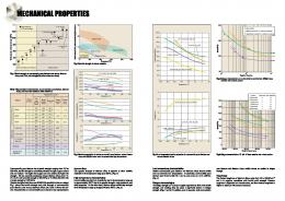
The relation of normal strain to normal stress was linear up to the ultimate stress, as presented on the graph in Fig. 4.
Figure 4 Relationship between normal strain and normal stress Slika 4. Odnos normalnog naprezanja i deformacije
Tehnički vjesnik 18, 2(2011), 273-280
D. Penava, I. Radić, G. Gazić, V. Sigmund
Mehanička svojstva ziđa za provjeru seizmičke otpornosti
The modulus of elasticity was determined as the secant modulus according to the Eq. (2) of the HRN EN 10521:2004 [4] as follows Ei =
Fi,max
(6)
3e i Ai
and is shown in Tab. 3. Table 3 Normal strains and secant modulus of elasticity Tablica 3. Normalne deformacije i sekantni modul elastičnosti
Ultimate normal strain εi,u / ‰ 0,54 0,72 0,63 0,54
Sample No. (i) 1 2 3 4
Normal strain εi / ‰ 0,13 0,16 0,15 0,14
Modulus of elasticity E / N/mm2 4978 4487 4527 4640
Figure 5 Front (back) side of the test specimen. Units are mm. Slika 5. Prednja (stražnja) ploha ispitnog uzorka. Jedinice su mm.
The average value of modulus of elasticity of masonry 2 in vertical direction was rounded up to 100 N/mm to 2 E=4600 N/mm . By applying the values of transverse and longitudinal strains at a third of the maximum stress, the Poisson's ratio was determined by
u i =-
e i,q ei
,
(7)
Table 5 The compressive strength of samples in horizontal direction Tablica 5. Tlačna čvrstoća uzoraka u horizontalnom smjeru
as shown in Tab. 4. Table 4 Poisson's ratio Tablica 4. Poissonov omjer
Sample No. (i) 1 2 3 4
Longitudinal strain εi / ‰ -0,13 -0,16 -0,15 -0,14
Transversal strain εi,q / ‰ 0,008 0,008 0,008 0,007
Poisson’s ratio υi /0,06 0,05 0,05 0,05
The values of measured longitudinal and transverse strains are given in Tab. 3 and the calculated Poisson's ratio of the masonry is υ = 0,05.
5 Horizontal compressive strength of masonry Tlačna čvrstoća ziđa u horizontalnom smjeru In order to determine the properties of masonry in horizontal direction the tests were carried out on three unreinforced masonry wallets in accordance with the norm HRN EN 1052-1:2004 [4]. The samples were produced in the same manner as samples in the previous section. The mortar was applied to the bed and head faces of masonry units and carefully kept out of masonry unit voids. Leveling layer of mortar was applied to the top and bottom surfaces of the masonry wallets. The tests were conducted after 28 days. Four LVDT-deformation sensors were placed in vertical direction (Va1, Vb1, Va2 and Vb2). Applied vertical force during testing was measured by force transducers. Dimensions of the sample and arrangement of the sensors are shown in Fig. 5. Technical Gazette 18, 2(2011), 273-280
There was a sudden brittle failure with multiple vertical cracks through the connection between the mortar and the masonry unit. In addition, the compressive failure occurred in the blocks leading to the collapse of the sample. Due to the sudden break of the test samples only basic information necessary for calculating the mechanical properties was collected. The terms by which the mechanical properties were determined are identical to those described in Chapter 4.
Sample No. (i) 1 2 3
Ultimate load Fh,i,max / kN
Area Ah,i / mm2
73,2 71,0 74,4
66875 66875 66875
Compressive strength fh,i / N/mm2 1,1 1,1 1,1
The average value of compressive strength in 2 horizontal direction of masonry wallets is fh=1,1 N/mm and 2 the mean characteristic value is fhk=0,91 N/mm . Table 6 Normal strains and secant modulus of elasticity Tablica 6. Normalne deformacije i sekantni modul elastičnosti
Sample No. (i) 1 2 3
Ultimate normal strain εh,i,u / ‰ 0,48 0,51 0,51
Normal strain εh,i / ‰ 0,18 0,20 0,20
Modulus of elasticity Eh,i / N/mm2 2054 1813 1854
The mean value of the modulus of elasticity was 2 identified to Eh=1900 N/mm and the Poisson's ratio was not determined.
6 Initial shear strength of masonry Početna posmična čvrstoća ziđa In order to determine the characteristic initial shear strength fvk0 and the characteristic angle of internal friction tanΦk, by following the guidelines of norm HRN EN 10523:2004 [5], twelve test samples were produced from the 275
Mechanical properties of masonry as required for the seismic resistance verification
D. Penava, I. Radić, G. Gazić, V. Sigmund
same mortar and masonry units, as shown in Fig. 6. The tests were conducted after 28 days, in series of four samples with 2 2 corresponding normal stresses fn,p=0,2 N/mm , 0,6 N/mm 2 and 1,0 N/mm , where n designated the series number (n = 1, 2 and 3).
Figure 6 The test specimen scheme Slika 6. Shema ispitnog uzorka
During the execution of experiments, the ultimate shear load Fi,max and corresponding normal load Fi,p were observed. After each experiment, the form of collapse was analyzed in order to accept or reject the test, because not all failure modes of the masonry units are allowed to happen.
Figure 8 a) regular and b) irregular failure of test specimen (masonry unit on the right) Slika 8. a) pravilni i b) nepravilni slom ispitnog uzorka (zidni element na desnoj strani)
Figure 7 The test specimen during testing Slika 7. Ispitni uzorak tijekom ispitivanja
The breakdown of samples in every series occurred at the contact of mortar and masonry unit and mostly on just one side only, as shown in Fig. 8a. The results of two samples from different series were discarded because there was a breakage and dismantling of masonry unit, which is irregular according to Appendix A of norm HRN EN 1052-3:2004 [5] as shown in Fig. 8b. Mean values of test results of the three series are shown by the means of diagram in Fig. 9. By using the linear regression curve and linear extrapolation the initial shear strength was determined as 2 fv0=0,47 N/mm and the angle of internal friction tanΦ=0,46. The characteristic values in accordance with the norm HRN EN 1052-3:2004 [5] were obtained as f vk 0 = 0 ,8 × f v 0 = 0 ,38
(8)
2
in N/mm and tanF k = 0 ,8 × tanF = 0 ,37.
276
(9)
Figure 9 Mean values of shear strength at different normal stresses Slika 9. Srednje vrijednosti posmične čvrstoće pri različitim normalnim naprezanjima
7 Tensile (shear) strength of masonry Vlačna (posmična) čvrstoća ziđa Tensile and shear strength of masonry was determined on four square samples of unreinforced masonry wallets by applying the diagonal tensile test in accordance with [6] and [9]. The samples were produced vertically and mortar was applied to the bed and head faces of masonry units and carefully kept out of masonry unit voids. Leveling layer of mortar was applied to the top and bottom surfaces of the masonry wallets. Before testing the sample was placed diagonally at an angle of 45 degrees towards horizontal with a special support. The tests were conducted after 28 days. A total of four LVDT-deformation transducers were used to measure the deformation and one force transducer was used for measuring the force. Two LVDT-deformation sensors were placed in vertical (Va1 andVb1) and two in horizontal direction (Ha1 and Hb1). Tehnički vjesnik 18, 2(2011), 273-280
D. Penava, I. Radić, G. Gazić, V. Sigmund
Mehanička svojstva ziđa za provjeru seizmičke otpornosti
The tensile and shear strength of masonry wallets were calculated by using the Eq. (3.12) of [4] and the Eq. (2) of [9] 2 Fi,max
ft =
(10)
p 2t·l s s
and Fi,max
fv =
(11)
2t·l s s
and presented in Tab. 7. Table 7 The tensile and shear strength of samples Tablica 7. Vlačna i posmična čvrstoća ispitnih uzoraka Figure 10 Front (back) side of the test specimen. Units are mm. Slika 10. Prednja (stražnja) ploha ispitnog uzorka. Jedinice su mm.
The position of the test sample and arrangement of the sensors are shown in Fig. 10. The loss of bearing capacity of the test samples occurred by sudden onset of irregular vertical cracks through the entire sample. The crack passed in part through the masonry unit and partly through contact of mortar and masonry unit as shown in Fig. 11 and the loss of adhesion and horizontal tensile strength of masonry units occurred. During testing, a sensor was destroyed due to sudden fracture. This was prevented in other attempts by supporting the sample from the sides (see Fig. 12).
Sample No. i
Ultimate load Fi,max / kN
Tensile strength 2 ft,i / N/mm
Shear strength 2 fv,i / N/mm
1
49
0,24
0,38
2
42
0,21
0,32
3
32
0,16
0,25
4
35
0,17
0,27
The average tensile and shear strength of the test 2 2 specimens were ft=0,19 N/mm and fv=0,31 N/mm with a 2 2 standard deviations of S=0,04 N/mm and S=0,06 N/mm and coefficients of variation of V=19 %, respectively. The mean values of characteristic strengths were calculated by using Eq. (3) of norm HRN EN 1052-1:2004 [2] which were fk =
f 1,2
(12)
or f k = fi,min
(13)
2
Figure 11 Failure of the test sample Slika 11. Slom ispitnog uzorka
2
as ftk=0,16 N/mm and fvk=0,25 N/mm . By this test method one can determine shear and normal deformation as well. As shown in Fig. 12 the relation between the shear strain and shear stress was linear up to the failure and the relation of tensile stress to tensile strain was nonlinear.
Figure 13 Relationship between shear strain and shear stress Slika 13. Odnos posmičnog naprezanja i posmične deformacije Figure 12 Total separation of the test sample Slika 12. Potpuno razdvajanje ispitnog uzorka Technical Gazette 18, 2(2011), 273-280
277
Mechanical properties of masonry as required for the seismic resistance verification
D. Penava, I. Radić, G. Gazić, V. Sigmund Table 9 A set of mechanical properties obtained for masonry wall tests Tablica 9. Skup dobivenih mehaničkih svojstava za zidne prizme
Figure 14 Relationship between tensile strain and tensile stress Slika 14. Odnos vlačne deformacije i vlačnog naprezanja
Test method
Number of samples
Vertical compression
4
Horizontal compression
3
Horizontal sliding
12
Diagonal tension
4
In accordance with [9], shear strain was determined by using the following expression 1 ö æ d h +d v ö æ gyx = ç tan a + tana ÷ø çè 2d ÷ø è
(14)
where d=1025 mm is the length of diagonal of the masonry wallet, δv and δh are vertical and horizontal diagonal extension respectively and α=45° is the angle of masonry wallet towards horizontal according to Fig. 10. The shear modulus was calculated by using the Hooke's law for shear G yx =
t yx g yx
,
(15)
where τxy was calculated according to Eq. 11 and Tab. 7. Table 8 The shear modulus, the diagonal normal and shear strains Tablica 8. Modul posmika, dijagonalne normalne i posmične deformacije
Ultimate diagonal strains
1
0,23
0,30
6,1×10 -4
Shear modulus Gyx,i / N/mm2 626
2
0,21
0,47
5,2×10 -4
626
3
0,14
0,34
4,0×10 -4
626
Sample No. i
εdh,i,u / ‰ εdv,i,u / ‰
4
0,25
0,47
Shear strain γyx, i / rad
4,3×10 -4
626
The average value of shear modulus of masonry was 2 2 rounded up to 100 N/mm to Gxy=600 N/mm as was the case with the modulus of elasticity.
8 Conclusion Zaključak The results of experimental investigation of the mechanical properties of masonry and its constituent elements are given as were performed by the use of simple experimental methods. Masonry wallets were tested inplane using Croatian/European norms and guidelines from [6] and [9]. The test results can be classified, as in the following table, with respect to type of the test and number of samples.
278
Mechanical property and value fk=1,7 N/mm2 E=4600 N/mm2 υ=0,05 εu=0,61 ‰ fhk=1,1 N/mm2 Eh=1900 N/mm2 εh,u=0,50 ‰ fvk0=0,38 N/mm2 tanΦk=0,37 ftk=0,16 N/mm2 fvk=0,16 N/mm2 Gyx =600 N/mm2 gyx,u =4,9×10⁻⁴rad εdh,u=0,21 ‰ εdv,u =0,40 ‰
The meaning of symbols can be found in Tab. 13. Through the execution of experiments it has been noticed that hollow clay masonry blocks are very brittle and they could affect the outcome of test, i.e. cause an incorrect failure type. These were in our case most often vertical cracks and crushing of hollow clay masonry units. Additional problems that arose were: (a) sudden failure of masonry at the moment at which it would be wise to remove the equipment that might be damaged like in the abrupt diagonal tension failure of the samples; (b) the importance of the quality of workmanship could be decisive, as mortar could infill the voids of masonry block and influence the results. The mechanical properties of the constituent elements of masonry, mortar and masonry units, are shown in the following tables. Table 10 A set of mechanical properties obtained for masonry units Tablica 10. Skup dobivenih mehaničkih svojstava za zidne elemente
Test method
Number of samples
Mechanical property and value
Vertical compression
6
fb=14,5 N/mm2
6
fbh=3,1 N/mm2
6
fbt=0,7 N/mm2
Horizontal compression Splitting tension
Table 11 A set of mechanical properties obtained for mortar Tablica 11. Skup dobivenih mehaničkih svojstava za mort
Test method
Number of samples
Compression Bending
6 3
Mechanical property and value fm=5,02 N/mm2 fmt=1,27 N/mm2
To represent the interdependence of some of the above parameters of masonry, it is useful to observe the law of orthotropic behavior of materials in plane stress condition, with a note that it is elastic state: Tehnički vjesnik 18, 2(2011), 273-280
D. Penava, I. Radić, G. Gazić, V. Sigmund
é 1 ê Ey ì e y ü êê ï ï ê 1 í e x ý = -n x Ey ïg ï ê î yx þ ê ê 0 ê ë
-n y
1 Ex
1 Ex 0
Mehanička svojstva ziđa za provjeru seizmičke otpornosti
ù 0 ú ú ìs ü úï y ï 0 ú ís x ý úï ï ú ît yx þ 1 ú G yx úû
of failure theories, for a more accurate prediction of its loss of bearing capacity. (16)
with
n y E y = n x Ex .
(17)
In Eq. 16 and Eq. 17, y designates the direction perpendicular to bed joints and x the direction parallel to the bed joints. Therefore, according to Eq. 17 and the Tab. 9
nx =ny
Ey Ex
= 0 , 05 ×
Figure 15 Relationship between individual strengths Slika 15. Odnosi između pojedinih čvrstoća
4600 = 0 ,12 1900
(18)
the Poisson's ratio in horizontal direction is υh=0,12, thus the orthotropic elasticity matrix is filled. Ratios of individual parameters obtained in this study are shown in Tab. 12. The values of individual strength are presented graphically in Fig. 15, from where it is clearly seen how compressive strength of masonry unit in vertical direction dominates. The weakest strength is the tensile strength of masonry, owing to low adhesion between mortar and masonry units and then initial shear strength or cohesion follows. The outlined extended testing of the masonry mechanical properties in plane has been necessary (as shown in the work [10]) for obtaining the parameters needed for the non-linear numerical calculation of the masonry. Presented data could be used as initial required values for numerical analysis of masonry as used in Croatia. Table 12 Mathematical relations between parameters Tablica 12. Matematički odnosi među parametrima
Parameters fbh/fb fbt/fb fhk/fk ftk/fk Eh/E Gyx /E εhu/εu εdh,u/εdv,u υ/υh
Mathematical relation fbh=0,21·fb fbt=0,05·fb fhk=0,65·fk ftk=0,09·fk Eh=0,41·E Gyx =0,13·E -
The research presented in this paper is part of the research project "Seismic design of infilled frames" supported by the Ministry of Science, Education and Sport of the Republic of Croatia and its support is gratefully acknowledged.
9 Notation Oznake The meaning of important symbols and indices used in this work is given in alphabetical order in the table below. Table 13 List of important symbols used in Latin characters Tablica 13. Popis bitnih simbola u latinici
Symbol Units
21 5 65 9 41 13 82 53 42
2
E
N/mm
Eh
N/mm2
fb
N/mm2
fbh
N/mm2
fbt
N/mm2
fk
N/mm2
fhk
N/mm2
ftk
N/mm2
fvk
N/mm2
fvk0
N/mm2
fm fmt Gyx x,y
N/mm2 N/mm2 N/mm2 -
Ratio / %
The nonlinear properties of masonry are dependent upon the amount and loading type and input data can be obtained only by experiment. Taking into account the wide range of variation of mechanical properties of masonry, the testing of masonry is one of the basic aspects of seismic resistance verification of masonry structures. Using the data obtained by testing will make the results of seismic resistance verification more accurate. Although the stress state in masonry is very complex and cannot be easily simulated in experiments, the properties obtained by simple experiments which explore the basic failure modes of masonry could be used, by means Technical Gazette 18, 2(2011), 273-280
Acknowledgments Zahvale
Meaning modulus of elasticity in vertical direction modulus of elasticity in horizontal direction normalized mean vertical compressive strength of masonry unit normalized mean horizontal compressive strength of masonry unit tensile strength of masonry unit mean vertical characteristic compressive strength of masonry mean horizontal characteristic compressive strength of masonry mean horizontal characteristic tensile strength of masonry mean horizontal characteristic shear strength of masonry mean characteristic initial shear strength compressive strength of mortar tensile strength of mortar shear modulus horizontal, vertical direction
279
Mechanical properties of masonry as required for the seismic resistance verification
D. Penava, I. Radić, G. Gazić, V. Sigmund
Table 14 List of important symbols used in Greek characters Tablica 14. Popis bitnih simbola s grčkim znakovljem
Symbol Units Φk
-
gyx,u εu εh,u
rad ‰ ‰
εdv,u
‰
εdh,u
‰
ν νh
-
Meaning mean characteristic angle of internal friction ultimate shear strain ultimate vertical normal strain ultimate horizontal normal strain ultimate diagonal strain in direction of compression diagonal ultimate diagonal strain in direction perpendicular to compression diagonal Poisson’s ratio for vertical direction Poisson’s ratio for horizontal direction
10 References Literatura [1] EN 1996-1-1:2005. Eurocode 6 - Design of masonry structures – Part 1-1: General rules for reinforced and unreinforced masonry structures. English version. European Committee for Standardization. CEN. Brussels, 2005. [2] HRN EN 772-2:2004. Metode ispitivanja zidnih elemenata – 1. dio: Određivanje tlačne čvrstoće (EN 772-1:2004). European Committee for Standardization. CEN. Brussels, 2004. [3] HRN EN 1015-11:2000. Metode ispitivanja mortova za ziđe – 11. dio: Određivanje čvrstoće pri savijanju i tlačne čvrstoće očvrslog morta (EN 1015-11:1999). European Committee for Standardization. CEN. Brussels, 1999. [4] HRN EN 1052-1:2004. Metode ispitivanja ziđa – 1. dio: Određivanje tlačne čvrstoće (EN 1052-1:1998). European Committee for Standardization. CEN. Brussels, 1998. [5] HRN EN 1052-3:2004. Metode ispitivanja ziđa – 3. dio: Određivanje početne posmične čvrstoće (prEN 10523:2001). European Committee for Standardization. CEN. Brussels, 2001. [6] Sorić, Z. Zidane konstrukcije I. Hrvatski savez građevinskih inženjera, Zagreb, 1999. [7] Self, M. W. Structural Properties of load-bearing concrete masonry. // Masonry: past and present / ASTM STP 589, American Society for Testing and Materials, 1975., pp. 233254. [8] Matoševic, Dj.; Sigmund, V.; Zovkić, J. Experimental testing of masonry and masonry piers. // Modeling of Structures / urednik Čolak Ivo. Mostar: Sveučilište u Mostaru, 2008. str. 397-408. [9] Bosiljkov, V.; Totoev, Z. Y.; Nichols, M. J. Shear modulus and stiffness of brickwork masonry:An experimental perspective. // Structural Engineering and Mechanics. 20, 1(2005). [10] Seim, W.; Schweizerhof, K. Nichtlineare FE-Analyse eben beanspruchter Mauerwerk-scheiben mit einfachen Werkstoffgesetzen. // Beton- und Stahlbetonbau, 92(1997). [11] Tomažević, M. Earthquake-Resistant Design of Masonry Buildings // Imperial College Press, London (2000).
Authors' addresses Adrese autora Penava Davorin, mr. sc. Radić Ivan, dipl. ing. građ. Gazić Goran, dipl. ing. građ. Sigmund Vladimir, prof. dr. sc. University of Osijek, Faculty of Civil Engineering Drinska 16a, HR-31000 Osijek
[email protected] [email protected] [email protected] [email protected]
280
Tehnički vjesnik 18, 2(2011), 273-280