Tim Owens, Young Pil Kim, Nanda Palaniappan, Jian Li, Steve Groothuis, Gordon Haller, Shixin Wang. R&D Process Development, Micron Technology, Inc.
Metal Gate Recessed Access Device (RAD) for DRAM Scaling
Nirmal Ramaswamy, Venkat Ananthan, David Hwang, Ravi Iyer, Chandra Mouli, Allen Mcteer, Sanh Tang, Kunal Parekh, Tim Owens, Young Pil Kim, Nanda Palaniappan, Jian Li, Steve Groothuis, Gordon Haller, Shixin Wang. R&D Process Development, Micron Technology, Inc. Boise, ID. d ramaswa my0:micron.com
Abstract-A functional DRAM with higher data retention characteristics than a planar access device has been demonstrated, using a metal gate recessed access device (RAD). Chemical vapor
deposition (CVD) and atomic layer deposition (ALD) were used to
deposit titanium nitride (TiN) and tantalum nitride (TaN), respectively. CVD TiN and ALD TaN-CVD TiN laminate gate stacks were integrated with a RAD module. ALD TaN-CVD TiN laminate gates showed enhanced drive current (IDs), higher transconductance (GM), higher mobility (PEFF) and reduced off current (IOFF) characteristics compared to CVD TiN gates. Device characteristics and reliability data for both the planar devices and
RADs are presented. The ALD TaN-CVD TiN laminate metal gate RAD showed much improved data retention characteistics compared to a conventional planar device with a poly silicon gate. The optimum thickness of ALD TaN in the laminate stack is discussed. INTRODUCTION Jn this work, a functional DRAM with higher data retention Ithan a planar access device has been demonstrated by using a metal gate recessed access device (RAD). With increasing DRAM bit density, scaling the access device becomes a challenge due to short channel effects (SCE) and increasing extemal resistance (Rext). Various groups have evaluated nonplanar access devices to extend the scalability of DRAM [1,2,3]. A recessed channel has been shown to decrease SCE [3]. A typical RAD has a polysilicon gate strapped with a metal conductor. Scaling down the height of this stack is a challenge. Spacers on the metal conductor result in constricted space for the digit and storage node contacts, leading to an increase in Ra,t as the unit cell is scaled. A plot of time to write (tj) versus Ra,t is shown in Fig. 1. A RAD with wordline buried under the silicon surface enables reduction in stack height and Ra,t by increasing the area available for contacts. Such aggressive scaling would require the replacement of polysilicon gate material with an appropriate low-resistance metal gate. In this work, we show the feasibility of a metal gate that can be used in a buried RAD process integration scheme. The wordline of choice should be thermally stable and maintain a high work function (WF) through the high thermal budget of the DRAM process flow. Titanium nitride (TiN) was deposited by chemical vapor deposition (CVD) and tantalum nitride was deposited by atomic layer deposition (ALD). CVD TiN and ALD TaN-CVD TiN laminate gate stacks were studied by fabricating planar transistors and were subsequently integrated. A mature 95nm, 512Meg SDRAM was used as the test vehicle. A TEM cross section of the metal RAD integrated into the standard wordline is shown in Fig.2.
PROCESS DESCRIPTION AND MATERIAL CHARACTERIZATION CVD TiN, ALD TiN, and ALD TaN have been previously investigated as candidates for metal gate electrodes [4,5] for planar and non-planar devices due to excellent thickness control, good step coverage, and high thermal stability. In this work, ALD TaN was deposited using a metal-organic precursor 1-4244-1113-0/07/$25.00 02007 IEEE.
42
and NH3. CVD TiN was deposited using TiCl4 and NH3. IOOA blanket films were characterized by x-ray reflectivity (XRR) and x-ray diffraction (XRD). As observed from the XRD patterns (Fig.3 and 4), CVD TiN films are crystalline with colu columnar grains, and grain growth post heat treatment is minimal. ALD TaN films are nanocrystalline as deposited and exhibit non-uniform crystallinity post heat treatment. Blanket stress variation of TiN film versus thickness is shown in Fig.5. Density (extracted from XRR) variation due to heat treatment is plotted inFlg.6 for TaN and TiN. TEM images (Fig 7) of 0ouA TaN flm post heat treatment show crystallites in an amorphous matrix. Post heat treatment, the interface of TaN/SiON was smoother and more distinct compared to the rough TiN/SiON
(Fig.8). Gate work function was obtained by Flat-band (VFB) versus effective oxide thickness (EOT) plots from MOS capacitors for both TiN and TaN-TiN gates. The as-deposited WF was calculated to be -5.OeV for both stacks (Fig.9). For the laminate gate stack, an optimum thickness of TaN is needed to prevent non-uniform crystallization, but still provide an improved interface. Laminate gates with thicker TaN films (>30A) show a shift in the CV curve post 1000°C, 20 second rapid thermal anneal (RTA) and a 700°C, 30-minute aimeal (Fig. 10 and 11). A 30A stack was chosen as optimum for the TaN thickness in the laminate stack for both the planar and RAD. PFETS were fabricated with 24A EOT SiON gate oxide with TiN and TaN-TiN to compare both gate stacks. RESULTS AND DISCUSSION
Comparison ofplanar transistor characteristics with TaN-TiN and TiN: From extracted WF values, both devices have similar threshold voltages (VT). Measured VT was -0.7V for TaN-TiN and -0.73V for TiN gates. TaN-TiN gates show 45 percent higher drive current (at drain to source voltage, VDS = 1.65V; gate voltage, VG = -2.OV) and 1 3X lower off-state leakage (Fig. 12), consistent with the higher peak transconductance (Fig. 13), higher effective mobility (Fig. 14), and lower subthreshold swing. Charge pumping measurements (Fig. 15) show 25 percent lower Nit with TaN-TiN gates compared to TiN gates. TaN-TiN gates also show lOX lower gate-induced drain leakage (GIDL) at gate to drain voltage VGD = 3V and 30X lower gate leakage current at VG= -3V (Fig. 16).
Comparison of 512Meg SDRAM with TaN-TiN RAD and planar poly silicon access devices: As expected, simulation showed increasedwordline capacitance with increased recess depth (Fig. 17 and 18). Intrinsic blanket stress values were used as input for 2-D ANSYS stress simulations. These simulations were used to compare stress levels of a polysilicon RAD to TiN metal RAD. The metal RAD exhibits high compressive stress levels in the channel due to the high intrinsic tensile stress of TiN (Fig. 19 and 5). Simulations (Fig. 20) show reduced Efield at the cell junction for the RAD compared to the planar access device. For a given IDS, the target Vt for a metal RAD is
-200mV lower than for a planar access device due to its longer TTNar as leppt effective channel length (Fig. 21). Improved subthreshold slope -TN700C30OC3n (Fig. 22) and drain induced barrier lowering (DIBL) (Fig. 23) -TN T000C30 indicate good scalability for metal RAD. The TaN-TiN device : :4 shows 15 percent higher IDS (Fig. 24), 6 percent higher BVDS (Fig. 25), 33 percent lower DIBL and similar sub-threshold =_ characteristics compared to the TiN RAD device. The metal 2 theb(degrees) RAD exhibited a shorter TDDB lifetime (Fig. 26) compared to reese a p-type poly planar structure with similar oxide thickness, due Figure 3. XRD pattern showing TiN Figure 4 XRD pattern showing to thinner oxide at the recess bottom (Fig. 27), as indicated by microstructure evolution with heat treatment. TaN microstructure evolution with heat treatment. the TEM cross section. TDDB results for a 60A gate oxide metal RAD show improvement of TDDB lifetime over devices 25 12 with 50A gate oxide. Parts with metal RAD met performance A, . specifications for this design. Data retention characterisic (Fig. 28) of the metal RAD are significantly better than a planar access device for this technology. -
CONCLUSION °5 ,00 200 300 100 S00 100 7L TaN-TiN laminate and TiN metal gates were studied as Thickness (A) possible choices for a metal gate RAD. Improved electrical Figure 5. Stress vs. thickness of TiN film. characteristics of the TaN-TiN laminate gates are attributed to the improved metal gate/SiON interface. For the first time, integration of a metal gate RAD with conventional thermal gate oxide was demonstrated. A fully functional 512Meg SDRAM As de osit_d with a metal RAD module was fabricated. Data retention time for a metal RAP was significantly improved compared to aa planar access device. Continued scaling of the DRAMV array transistor is possible using a buried metal gate module. -_ ''n
/
i I
et T--t
Figurea6. Variationofdensitywithheat 750C
REFERENCES
[1] C.J.Radens et al., VLSI Symp Tech. Dig., 2000, pp. 0-81 . [2] R. Weis et al., IEDM Tech. Dig., 200 1, pp. 18.7.1-187.4 [3J. J.Y.Kim et al., VLSI Symp Tech. Dig., 2003, pp. 11-12. [4] D.G.Park, et al.,iElec. Soc., 148,9,F 189-F 193, 2001. [5] J.Westlinder et al., IEEE Elec. Dev Lett.,24,9,550-552,2003.
Figure 7. TaN film shows crystallites in an amorphous matrix post heat
3-0 250
3
0
45 1.0 00
C)
°
20
30
40
~~RSd(kQ4)_
50
60
Figure 8. TEM micro graph of metal gate/SiON interface post 1,000°C,
Figure 1. Correlation between RSD and time
20s RTP. Significant interface roughening is observed with TiN.
TaN
TaN1IOA
TaN 20A
TaN40A
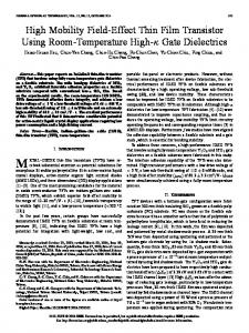
Figure 2. SEM x-sec showing the RAD with a TiN gate. The stack above the silicon surface is the standard wordline used for a planar access device. PEELS scan across the recess shows the transition from silicon to oxide to TiN.
EOT(A2
Figure 9. V7 4vs. EOT plots for as- G- VOg. (VG) deposited TaN and TiN gate stacks. Figure 10. CV curves for various thicknesses of TaN in TaN-TiN laminate stack from MOSCAPs, pre heat treatment.
43
40
tl=_g*m.1@)|>8E40~3 ~ 0|2- ~ 195T.N20A
TaN
30
4OA
TNG
25
\\1
1Sr*I
26 20 1000C 20sTi O15 RTP,700C 30 minutes 10 5 .
0
2 o
-3
-2
-1
0
Gate Voltage
1
2
1111 12
-field.
s
o
I I
I I
1'
I I
Figure 12. ID-VG characteristics at VDS= 1.65V:
TiN
¶xPoIy R~J~
Stress-yy
Figure 18. RAD array cell structure used in Raphael to calculate wordline capacitance.
E
o'o
o'
Figure 17. Wordline capacitance simulation of metal RAD vs. RAD depth.
T,Nth Na-i gat.AADdeth
Figure 21. Access device VT
~1. TIN
. . . . . . . . . . .t MEANS
comparison between conventional
poly Si device and metal RAD.
Stress-xx
(GPa) (GPa) WE C. L.' 04 0)4 O{& 0.08 a24 a'. Figure 19. 2-D ANSYS stress simulation comparison for RAD with poly silicon gate and TiN metal gate. Figures a and b show stress in YY direction and figures c and d show stress in XX direction.
102 o2 aU4
o's
lower I- and hiTher I-qwith TaN-TiN gate.
characteristics:~~~~~~~~~~~~~~~~~~~~~~~~~~~~~~ Powe i with
FiPgureRAID
1'
Gate VO1tge (V,)
Figure 13. GM-VG characteristics at VDS= 1.65V:
lower I- and hiTher I-qwith TaN-TiN gate.
Figue ChrgeFigure 16. Gate leakage Fiue15. Chrepumping characteristics: lower leakage characteristics: lower Nit with with TaN-TiN gate. TaN-TiN gate.
11
Figure 14. Effective hole mobility vs. F
0%'2'
-
Gate Voltage (VG)
3
(V.
Figure 11. CV curves post heat treatment: shift to lower WF is observed for thicker TaN films in TaN-TiN gate.'-
E,(MV/em)
=
01
2726-
25-
222-
0-~~~~~~~~~~~~~0
...... || |
20-
75 1
Figure 20. Simulation of E-field for planar access device and RAD.
8 5-
1
_ 24~ ~ ~ ~ ~ ~ ~ ~ ~3~ ~ -4
~~~~~~~~~~~~21-
0-
.t t
__E-Sa
~~~~~~~~~~~~~~~~~~~~~23-
90-
o
TaD poyPAD Figure 22. Subthreshold slope P
S
RAD TaN/TiN
RAD TIN
Figure 24. Drive current (IDS)
TNN
comparison between conventional poly Si device and metal RAD.
Planar poy Si
RADTN
Figure 23. DIBL comparison between conventional poly Si device and metal RAD.
comparison between conventional
poly Si device and metal RAD.
aP,9 eaRD soi4
8-~~~~~~~~~~~~~~~~~~~~~~~~~~~~~~~~~~~~~~~4
7 5lo,
7
8o-8
a 0
Device
~~~~~~~~~~~~~~~~~~~~Planar
07Odi.
E
Z1 /26] ~~~~~~~~~~~~~~~~~~~0130
Gate Voltage
Fig. 25. Breakdown voltage comparison between conventional poly Si device and metal RAD.
" [_ ~: < l
-2-Mea
V,
A _
Figure 26. TDDB lifetime
comparison.
Figure. 27. Gate oxide thinning observed at bottom of RAD trenc
44
M l RD-
Figure 28. Time for 200 cells to fail. (arb. units).
Data retention characteristics of 512MB SDRAM.
t