Diamond & Related Materials 69 (2016) 160–165
Contents lists available at ScienceDirect
Diamond & Related Materials journal homepage: www.elsevier.com/locate/diamond
Microstructure and mechanical properties of carbon nanotubes/AZ31 magnesium composite gas tungsten arc welding filler rods fabricated by powder metallurgy A. Sabetghadam-Isfahani a, M. Abbasi b, S.M.H. Sharifi a, M. Fattahi c,⁎, S. Amirkhanlou d, Y. Fattahi b a
Mechanical Engineering Department, Petroleum University of Technology, Ahwaz, Iran Materials Engineering Department, Isfahan University of Technology, Isfahan, Iran c Technical Inspection Engineering Department, Petroleum University of Technology, Abadan, Iran d Institute of Materials and Manufacturing, Brunel University London, London UB8 3PH, United Kingdom b
a r t i c l e
i n f o
Article history: Received 11 June 2016 Accepted 29 August 2016 Available online 31 August 2016 Keywords: Carbon nanotubes AZ31 magnesium alloy Mechanical properties Powder metallurgy
a b s t r a c t In the present study, carbon nanotubes/AZ31 magnesium composite filler rods of gas tungsten arc (GTA) welding were fabricated for the first time by powder metallurgy. After welding, the effect of carbon nanotubes (CNTs) on the microstructure and mechanical properties of nanocomposite welds was evaluated. By applying ball milling, CNTs were uniformly distributed in the filler rods. Consequently, the nanocomposite welds produced by these filler rods had a uniform distribution of CNTs in their compositions. Tensile tests revealed that the tensile strength of 1 wt% CNTs-reinforced weld was increased by 65% compared with unreinforced weld. Therefore, it can be concluded that CNTs can be good reinforcement candidates in GTA welding of magnesium and its alloys. © 2016 Elsevier B.V. All rights reserved.
1. Introduction Magnesium and its alloys are one of the most promising materials for application in the aerospace, aircraft and automotive industries due to their low density, high specific strength and stiffness, high damping capability and good formability. In order to increase the applications of magnesium alloys, there is need to apply more efficient welding parameters and techniques. Due to the advantages of utility and economy, gas tungsten arc (GTA) welding is the main adopted welding method for magnesium alloys. In GTA welding, an electric arc is established between a non-consumable tungsten electrode and the base metals. The arc melts and joints base metals by thermal energy. An inert shielding gas such as argon, helium or a mixture of both of them is applied for protecting the weld pool from atmospheric contamination and a filler rod is normally used [1–3]. Carbon nanotubes (CNTs) have attracted great attention as excellent reinforcements in magnesium matrix composites (MMCs) due to their unique mechanical properties [4–8]. Mechanical properties of CNTs-reinforced MMCs are influenced by the following factors: uniform dispersion of CNTs in the matrix, maintenance the chemical and structural integrity of CNTs in the matrix and formation of strong interfacial bonding to attain effective load transfer between the matrix and CNTs [9–13]. Powder metallurgy (PM) is the most promising process for producing homogenous CNTs-reinforced MMCs. Various researchers have investigated the mechanical properties of CNTs-reinforced MMCs produced by ⁎ Corresponding author. E-mail address:
[email protected] (M. Fattahi).
http://dx.doi.org/10.1016/j.diamond.2016.08.017 0925-9635/© 2016 Elsevier B.V. All rights reserved.
PM process [14–16]. Rashad et al. [14] showed that the addition of CNTs to the AZ31 magnesium alloy using PM could considerably improve the dispersion of CNTs and increase the tensile strength of composite. Fukuda et al. [15] applied PM to fabricate the MMCs and noted that with increasing CNT content, the mechanical properties was increased. Li et al. [16] investigated the effect of CNTs on the mechanical properties of MMCs prepared by PM. It was shown that Orowan strengthening mechanism, load transfer mechanism and grain refinement play important roles on the increase of tensile strength. The chemical composition of filler rod has significant effect on the microstructure and mechanical properties of GTA welds. Employing nanotechnology to welding science reveals new opportunity for the development of modern filler rods [17–20]. It seems that the application of CNTs-reinforced MMCs as the filler rod for GTA welding of magnesium alloys is an interesting idea to attain better weld properties. In this study, CNTs/AZ31 magnesium composite filler rods were fabricated by PM process. After welding, the effect of CNTs on the microstructures and mechanical properties of GTA welds was investigated. 2. Experimental procedure Multi-walled CNTs with the average external diameter of 50 nm and AZ31 magnesium alloy powders (Mg-3 wt% Al-1 wt% Zn) with the average particle size of 60 μm were used as the starting materials. Fig. 1 shows the scanning electron microscopy (SEM) micrographs of the asreceived CNTs and AZ31 magnesium alloy powders. To produce the CNTs/AZ31 magnesium composite filler rods of GTA welding, the PM method was used. Fig. 2 shows a schematic illustration
A. Sabetghadam-Isfahani et al. / Diamond & Related Materials 69 (2016) 160–165
161
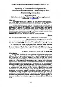
Fig. 1. SEM micrographs of: (a) the as-received CNTs and (b) the AZ31 magnesium alloy powders.
of the experimental procedure used for the fabrication of CNTs/AZ31 magnesium composite filler rods. The fabrication process of CNTs/ AZ31 magnesium composite filler rods includes three steps. At the first step, CNTs were dispersed in ethanol using an ultrasonic bath at room temperature. After drying, 1 wt% CNTs were added to the AZ31 magnesium alloy powders. About 100 g of CNTs/AZ31 magnesium composite powders were placed in a stainless steel bowl and balls with the diameters of 20 mm were added. Ball milling was performed in a planetary ball mill at a constant speed of 300 rpm for 4 h under argon atmosphere with ball to power ratio of 10:1 with 1 mL methanol addition into the dried mixture as process control agent. In order to prevent heating, the milling was break for 10 min in every 1 h. In the second step, the compaction of composite powders was performed in a stainless steel die under 500 MPa pressure to obtain solid compacts of 20 mm diameter and then the compacts were sintered for 1 h under 400 °C. In the final step, the hot extrusion process of solid compacts was performed at 400 °C with an extrusion ratio of 5:1 to attain the filler rods of 4 mm diameter. In order to comparison, the filler rods without CNTs were also fabricated from the AZ31 magnesium alloy powders using above method. Hot-rolled AZ31 magnesium alloy sheets with the dimensions of 150 mm × 100 mm × 10 mm and a single V-shaped groove with an angle of 60° were used as the base metal. The arc voltage, arc current and the flow rate of argon shielding gas employed in GTA welding process were 15 V, 180 A and 16 L min−1, respectively. Optical microscopy
(OM, Olympus DP72) and scanning electron microscopy (SEM, Tescan Vega II XMU) combined with a Rontec energy dispersive X-ray spectrometry (EDS) were used to examine the effect of CNTs on the microstructure and mechanical properties of welds. To evaluate the distribution of CNTs and intermetallic phases in the welds, the metallographic samples were cut perpendicular to the welding direction and were examined after machining and etching with a solution containing 2 g picric acid, 50 mL ethyl alcohol and 5 mL acetic acid. Vickers microhardness measurements with a load of 50 g for 20 s were performed using an Akashi MVK-H21 microhardness tester. Sub-sized tensile test specimens with a gauge length of 30 mm and a specimen diameter of 6 mm were machined according to ASTM E8M standard. Fig. 3 schematically illustrates the location of tensile test specimen in the welded joint. Tensile tests were performed using a Hounsfield H25KS machine at room temperature with a constant cross-head speed of 5 mm min−1. The fracture surfaces of tensile test specimens were investigated by SEM. 3. Results and discussion Fig. 4 shows the SEM micrographs of 1 wt% CNTs/AZ31 magnesium composite powders at different magnifications after ball milling. It can be seen from Fig. 4a and b that the composite powders were changed to flake morphology. In Fig. 4c and d, the higher magnification micrographs of uniformly dispersed CNTs in the composite powders are
Fig. 2. Schematic illustration of the procedure to fabricate CNTs/AZ31 magnesium composite filler rods.
162
A. Sabetghadam-Isfahani et al. / Diamond & Related Materials 69 (2016) 160–165
Fig. 3. Weld test assembly showing the location of tensile test specimen (all dimensions are in mm).
Fig. 4. (a–d) SEM micrographs of the ball-milled powder showing uniform dispersion of CNTs in the matrix at different magnifications, respectively.
A. Sabetghadam-Isfahani et al. / Diamond & Related Materials 69 (2016) 160–165
shown. The agglomerated CNTs were not exist in the ball-milled powders that means CNTs have been uniformly distributed in the flakeshaped composite powders. Uniform distribution of CNTs have great effect on improving the mechanical properties of CNTs/AZ31 magnesium composites. Ball milling is more effective for the uniform distribution of CNTs in the MMCs in compare with the melt processing methods [14, 16]. Since CNTs are non-wettable with most of the molten metals and have large specific surface area form clusters [9]. Moreover, because of contact with the molten metals, there is the possibility of chemical reactions and carbide formation and thus CNTs are destroyed [12]. During ball milling, the agglomerated CNTs are broken and joint to the magnesium powders by mechanical interlocking. It can be concluded that the composite filler rods with a uniform distribution of CNTs and a good interfacial bonding are obtained by PM. Fig. 5a and b exhibits the SEM micrograph and carbon EDS mapping of the weld that prepared by the filler rod containing 1 wt% CNTs. It can be observed that a uniform and agglomeration-free dispersion of CNTs within the reinforced weld is obtained. The presence and structural integrity of CNTs in the reinforced weld is confirmed by Raman spectra in Fig. 5c. Raman spectra of CNTs usually contains three prominent bands i.e., D, G and 2D bands. The peaks at 1362 cm− 1, 1599 cm− 1 and 2716 cm−1 correspond to D-band (defect related), G-band (graphite related) and 2D bands, respectively. With regard to Fig. 5c, it is seen that CNTs have not been destroyed during the GTA welding process. Uniform distribution of CNTs in the weld confirms that CNTs are homogenously dispersed in the filler rods. Thus, PM method is a successful method for producing CNTs/AZ31 magnesium composite filler rods. Moreover, the high cooling rate in GTA welding can help to prevent the agglomeration of CNTs in the weld pool. Fig. 6a shows the optical micrograph of microstructure of 1 wt% CNTs-reinforced weld. The addition of CNTs to the weld is found to be
163
beneficial for grain refinement due to the capability of CNTs to nucleate α-Mg grains and the pinning force of CNTs against the movement of grain boundaries during grain growth [2,17]. From the SEM micrograph and EDS elemental mapping (Fig. 6b and c), it is seen that the black particles can be recognized as the eutectic β (Mg17Al12) phase. It can be observed that the eutectic β phase is uniformly distributed within the αMg grains. Rashad et al. [14] reported that the addition of CNTs to the AZ31 magnesium alloy dissolves and isolates the eutectic β phase throughout the matrix, leading to refinement of eutectic β phase. The tensile properties and microhardness of the welds and base metal are given in Table 1. Compared with the unreinforced weld, the tensile strength, yield strength and microhardness of 1 wt% CNTs-reinforced weld were obviously increased. The main reasons of this difference are excellent mechanical properties of CNTs, uniform distribution of CNTs in the weld and formation of strong interfacial bonding between the matrix and CNTs. Various mechanisms could lead to the improvement in the tensile strength of CNTs-reinforced welds that are: (a) coefficient of thermal expansion (CTE) mismatch, (b) Orowan looping, (c) shear lag and (d) grain refinement [9,17]. There are great differences between the CTE of AZ31 magnesium matrix and CNTs reinforcement. CNTs have a CTE of 1 × 10⁻⁶ K− 1, while magnesium exhibits a much greater CTE of 28.4 × 10⁻⁶ K−1. When weld pool is cooling down from the welding temperature, this difference lead to formation of new dislocations in the weld. Thereby, the addition of CNTs to the weld results in an increase in the density of dislocations, thus improvement in the tensile strength. CNTs can also act as precipitates and barriers against the motion of dislocations and pile up them. Dislocations during passing through CNTs would bend between them and leave dislocation loops that result in buildup dislocation forests [12]. The increase in the dislocations
Fig. 5. (a) SEM micrograph, (b) carbon EDS mapping and (c) Raman spectra of 1 wt% CNTs-reinforced weld, respectively.
164
A. Sabetghadam-Isfahani et al. / Diamond & Related Materials 69 (2016) 160–165
Fig. 6. (a) Optical micrograph, (b) SEM micrograph and (c) aluminum EDS mapping of 1 wt% CNTs-reinforced weld, respectively.
density leads to an increase in the cold working and tensile strength. This mechanism known as Orowan looping. The tensile strength of reinforced weld can also increase due to other mechanism such as shear lag. Under tensile testing, the applied load can be transferred from the softer matrix to the stiffer CNTs by means of interfacial shear stresses. CNTs stand out against tensile fracture that result to an increase in the tensile strength of reinforced weld [17]. In order to achieving effective load transfer, there is need to strong bonds between the weld matrix and CNTs [15]. By adding CNTs to the weld, grain refinement is achieved by the nucleation of α-Mg grains on CNTs and the suppression of grain growth due to the pinning of grain boundaries. The average grain size of α-Mg in the unreinforced weld was measured as 46 μm, whereas this value was measured as 32 μm for the reinforced weld. Decreased grain size of α-Mg in the reinforced weld can increase the tensile strength due to an increase in the density and distribution of dislocations. According to the Hall-Petch equation, it is well known that the tensile strength is increased with decreasing the grain size. The SEM micrographs obtained from the fractured surfaces of tensile test specimens are shown in Fig. 7. From comparison of the fracture surfaces of 1 wt% CNTs-reinforced and unreinforced weld samples in Fig. 7a and b can be seen that the fracture surface of unreinforced weld sample is covered by large dispersion of cleavage planes, while the fracture surface of 1 wt% CNTs-reinforced weld sample is mostly covered by dimples. Some of dimples in the 1 wt% CNTs-reinforced weld are larger that distributed among fine dimples. Presence of smaller dimples in the fracture surface of 1 wt% CNTs-reinforced weld in compare with
unreinforced weld, confirms the uniform elongation. Furthermore, there is a direct relation between increase in the tensile strength and decrease in the dimples size [19]. The addition of CNTs to the weld cause to prevent the motion of dislocations, so the dislocations density is increased, and the strain-hardening rate is improved. Higher magnification SEM micrograph of the fracture surface of 1 wt% CNTs-reinforced weld is shown in Fig. 7c. It can be seen that well dispersed CNTs without agglomeration are in the weld matrix. The agglomerated CNTs form weak bonds with the matrix that can lead to insufficient load transmission from the matrix to CNTs and decrease the tensile strength. There are two types of failure modes of CNTs in the matrix: (a) pulling out and (b) breakage [10]. The increase in the bond strength between the matrix and CNTs, cause to effective load transmission from the matrix to CNTs, thereby the mode of fracture will change from “pulling out” to “breaking” and improve the tensile strength.
4. Conclusions CNTs/AZ31 magnesium composite filler rods of GTA welding were successfully fabricated by PM process. The microstructure, mechanical properties and fracture surface morphology of welds were investigated. The test results showed that the tensile strength of weld was greatly increased when using the 1 wt% CNTs/AZ31 magnesium composite filler rods. The improvement in the tensile strength was attributed to the uniform distribution of CNTs and grain refinement. Thus, it can be
Table 1 Mechanical properties of the welds and base metal. Materials
Mechanical properties Tensile strength (MPa)
Yield strength (MPa)
Elongation (%)
Microhardness (HV)
Base metal (AZ31 Mg alloy) Unreinforced weld 1 wt% CNTs-reinforced weld
256 ± 5.7 177 ± 4.5 272 ± 7.2
179 ± 6.2 101 ± 4.0 186 ± 5.6
19 ± 3.4 8 ± 2.1 6 ± 1.5
64 ± 2.0 53 ± 4.5 67 ± 3.6
A. Sabetghadam-Isfahani et al. / Diamond & Related Materials 69 (2016) 160–165
165
Fig. 7. SEM micrographs of the fracture surfaces of the welds after tensile test: (a) unreinforced weld, (b) 1 wt% CNTs-reinforced weld and (c) higher magnification image of (b), respectively.
concluded that CNTs/AZ31 magnesium composite filler rod can serve as a novel filler rod to improve the mechanical properties of GTA welds. References [1] L. Liu, C. Dong, Gas tungsten-arc filler welding of AZ31 magnesium alloy, Mater. Lett. 60 (2006) 2194–2197. [2] A. Sabetghadam-Isfahani, H. Zalaghi, S. Hashempour, M. Fattahi, S. Amirkhanlou, Y. Fattahi, Fabrication and properties of ZrO2/AZ31 nanocomposite fillers of gas tungsten arc welding by accumulative roll bonding, Arch. Civ. Mech. Eng. 16 (2016) 397–402. [3] S. Chai, D. Zhang, F. Pan, J. Dong, F. Guo, Y. Dong, Influence of post-weld hot rolling on the microstructure and mechanical properties of AZ31 magnesium alloy sheet, Mater. Sci. Eng. A 588 (2013) 208–213. [4] H. Fukuda, K. Kondoh, J. Umed, B. Fugetsu, Fabrication of magnesium based composites reinforced with carbon nanotubes having superior mechanical properties, Mater. Chem. Phys. 127 (2011) 451–458. [5] C.D. Li, X.J. Wang, W.Q. Liu, H.L. Shi, C. Ding, X.S. Hu, M.Y. Zheng, K. Wu, Effect of solidification on microstructures and mechanical properties of carbon nanotubes reinforced magnesium matrix composite, Mater. Des. 58 (2014) 204–208. [6] M. Rashad, F. Pan, M. Asif, L. Li, Enhanced ductility of Mg–3Al–1Zn alloy reinforced with short length multiwalled carbon nanotubes using a powder metallurgy method, Prog. Nat. Sci.: Mater. Int. 25 (2015) 276–281. [7] G. Han, Z. Wang, K. Liu, S. Li, X. Du, W. Du, Synthesis of CNT-reinforced AZ31 magnesium alloy composites with uniformly distributed CNTs, Mater. Sci. Eng. A 628 (2015) 350–357. [8] C.D. Li, X.J. Wang, W.Q. Liu, K. Wu, H.L. Shi, C. Ding, X.S. Hu, M.Y. Zheng, Microstructure and strengthening mechanism of carbon nanotubes reinforced magnesium matrix composite, Mater. Sci. Eng. A 597 (2014) 264–269. [9] S.C. Tjong, Recent progress in the development and properties of novel metal matrix nanocomposites reinforced with carbon nanotubes and grapheme nanosheets, Mater. Sci. Eng. R 74 (2013) 281–350.
[10] B. Chen, S. Li, H. Imai, J. Umeda, M. Takahashi, K. Kondoh, Inter-wall bridging induced peeling of multi-walled carbon nanotubes during tensile failure in aluminum matrix composites, Micron 69 (2015) 1–5. [11] A.M.K. Esawi, K. Morsi, A. Sayed, M. Taher, S. Lanka, Effect of carbon nanotube (CNT) content on the mechanical properties of CNT-reinforced aluminium composites, Compos. Sci. Technol. 70 (2010) 2237–2241. [12] S.R. Bakshi, A. Agarwal, An analysis of the factors affecting strengthening in carbon nanotube reinforced aluminum composites, Carbon 49 (2011) 533–544. [13] A. Esawi, K. Morsi, Dispersion of carbon nanotubes (CNTs) in aluminum powder, Compos. A: Appl. Sci. Manuf. 38 (2007) 646–650. [14] M. Rashad, F. Pan, J. Zhang, M. Asif, Use of high energy ball milling to study the role of grapheme nanoplatelets and carbon nanotubes reinforced magnesium alloy, J. Alloys Compd. 646 (2015) 223–232. [15] H. Fukuda, K. Kondoh, J. Umeda, B. Fugetsu, Interfacial analysis between Mg matrix and carbon nanotubes in Mg–6 wt.% Al alloy matrix composites reinforced with carbon nanotubes, Compos. Sci. Technol. 71 (2011) 705–709. [16] C.D. Li, X.J. Wang, K. Wu, W.Q. Liu, S.L. Xiang, C. Ding, X.S. Hu, M.Y. Zheng, Distribution and integrity of carbon nanotubes in carbon nanotube/magnesium composites, J. Alloys Compd. 612 (2014) 330–336. [17] M. Fattahi, N. Nabhani, E. Rashidkhani, Y. Fattahi, S. Akhavan, N. Arabian, A new technique for the strengthening of aluminum tungsten inert gas weld metals: using carbon nanotube/aluminum composite as a filler metal, Micron 54-55 (2013) 28–35. [18] M. Fattahi, A.R. Gholami, A. Eynalvandpour, E. Ahmadi, Y. Fattahi, S. Akhavan, Improved microstructure and mechanical properties in gas tungsten arc welded aluminum joints by using graphene nanosheets/aluminum composite filler wires, Micron 64 (2014) 20–27. [19] M. Fattahi, M. Mohammady, N. Sajjadi, M. Honarmand, Y. Fattahi, S. Akhavan, Effect of TiC nanoparticles on the microstructure and mechanical properties of gas tungsten arc welded aluminum joints, J. Mater. Process. Technol. 217 (2015) 21–29. [20] M. Fattahi, V. Noei Aghaei, A.R. Dabiri, S. Amirkhanlou, S. Akhavan, Y. Fattahi, Novel manufacturing process of nanoparticle/Al composite filler metals of tungsten inert gas welding by accumulative roll bonding, Mater. Sci. Eng. A 648 (2015) 47–50.