Original Article
Microstructure and mechanical properties of Inconel-625 welded joint developed through microwave hybrid heating
Proc IMechE Part B: J Engineering Manufacture 1–16 Ó IMechE 2017 Reprints and permissions: sagepub.co.uk/journalsPermissions.nav DOI: 10.1177/0954405417697350 journals.sagepub.com/home/pib
Ravindra Ishwar Badiger1, S Narendranath1 and M S Srinath2
Abstract Application of microwave energy for processing of bulk metals is effectively utilized to join Inconel-625 plates through hybrid heating technique using Inconel-625 powder as an interface filler material. Post welding characterization of microwave developed joints through X-ray diffraction shows the development of carbides of niobium and chromium as well as intermetallic phases along with the primary g-phase face-centered cubic matrix. Microstructural examination reveals the formation of Laves phase along the grain boundaries in the fusion zone. Microwave-induced joints exhibit average microhardness of 245 6 20 HV and 0.7% porosity in the fusion zone. Average ultimate tensile strength and flexural strength of the developed joints were estimated at 375 and 377 MPa respectively. Average impact toughness of microwave-induced joints is observed to be 18 J.
Keywords Microwave, Inconel-625, susceptor, tensile strength, impact toughness, flexural test
Date received: 21 June 2016; accepted: 27 January 2017
Introduction Inconel-625 is a solid solution nickel-based super alloy strengthened by the addition of chromium, molybdenum, niobium and carbon. Because of its superior properties it plays a crucial role in development of strategic industries where the use of super alloys is obligatory. The alloy finds wide applications in gas turbines, aircraft engines, marine industries and chemical power plants due to its superior properties in terms of strength, corrosion resistance and creep resistance at high temperatures.1 The alloy is also prominently known for its unique combination of yield strength, tensile strength, fatigue strength, creep strength and excellent weldability.2 Fabrication of nickel-based super alloy components generally involves two approaches: first, they can be made as an integrated casting, and second, the parts can be joined to form the final assembly. Components made from nickel-based super alloy when exposed to harsh operating environments such as high temperature, oxidizing and reducing conditions for longer periods give rise to cracks that propagate through the surface irregularities and cause failure of the parts. Consequently, as nickel-based super alloy is very costly,
it is often advantageous to repair the damaged parts rather than to replace them with a new one.3 Joining of nickel-based super alloys over the years is primarily being carried out by means of gas tungsten arc welding, electron beam welding, laser beam welding, explosion welding, plasma arc welding and friction stir welding.1,4,5 Conventional fusion welding processes are easily available and more flexible among the existing welding techniques for joining nickel-based alloys. Although these processes are popular, the extreme heat generated through these processes, formation of hot cracks, segregation of Nb and Mo rich phase result in formation of Laves phase and significant change in microstructures of both heat-affected zone and weld zone that lead to inferior mechanical properties and
1
Department of Mechanical Engineering, National Institute of Technology Karnataka, Surathkal, India 2 Department of Mechanical Engineering, Malnad College of Engineering, Hassan, India Corresponding author: Ravindra Ishwar Badiger, Department of Mechanical Engineering, National Institute of Technology Karnataka, Surathkal 575025, Karnataka, India. Email:
[email protected]
2 decreased corrosion resistance.4 Moreover, the necessity of shielding gas in laser beam welding and maintaining high vacuum during electron beam welding process as well as the higher power requirements associated with laser welding process jointly increase the operating costs. Considerable works have been carried out in the past to characterize the welded joints of Inconel-625 alloy. Researchers have reported that during the solidification of Inconel-625, due to segregation of Nb formation of Laves phase takes place which is detrimental to the strength of the welded joints. Silva et al.6 investigated the solidification process during tungsten inert gas (TIG) welding of C–Mn steel plates using Inconel-625 filler wire. The authors proposed a new path for solidification of the weld overlay so as to reduce the formation of Laves phase in the solidified alloy. Xu et al.7 studied the pulsed plasma arc welding of Inconel-625 alloy and reported the occurrence of Laves phase, NbC/TiC phase and Ni–Nb phase in Ni matrix. Li et al.1 performed dissimilar welding of Inconel-625 alloy with SUS304 using CO2 welding. Formation of Laves phase was observed at the grain boundaries and in the interdendritic regions of fusion zone due to segregation of Nb that reduced the tensile strength as well as toughness of the welded joint. Recently, Ramkumar et al.8 carried out dissimilar welding of Inconel-625 alloy with UNS 32205 through electron beam welding process. The dissimilar joint exhibited poor impact strength due to segregation of Mo in the interdendritic regions. Furthermore, formation of Laves phase causes cracking during welding of Inconel-625 alloy. The cracking in the weldment can be eliminated by providing reduced heat input to the process. Wilson et al.9 studied the effect of heat input on microstructure and cracking in Inconel-625 alloy welds deposited through plasma arc (highest heat input), TIG and laser beam (lowest heat input) welding processes. Microstructure of plasma arc welding specimens revealed the presence of cracks, whereas no cracks were observed with other two cases. It has been reported that lower heat input to the welding process results in rapid cooling that leads to lower amount of segregation of alloying elements. Song and Nakata10 reported on the mechanical properties of friction stir welded Inconel-625 joints. The welded joints exhibited microhardness and tensile strength values higher than that of the base metal. Kondapalli et al.5 employed micro-plasma arc welding to join Inconel-625 sheets. The authors reported on optimization of welding parameters to maximize ultimate tensile strength (UTS) of the joint produced. Significant increase in UTS was observed; however, the overall equipment cost is high and the process calls for the use of shielding gas. Janicki11 studied the influence of welding parameters on weld quality and strength of Inconel-625 sheets welded using direct diode laser. High purity argon gas was used for shielding the weld zone during the process and UTS up to 15% lower than that of base metal was achieved. Joining of Inconel-625 with conventional
Proc IMechE Part B: J Engineering Manufacture 00(0) fusion welding techniques suffers from significant drawbacks that present favorable circumstances to search for new cost-effective processing technique that provides low heat input during welding. Processing of materials through microwave energy has opened up a new research area and is being accepted by the manufacturing industries. In microwave processing of materials, heating takes place from center towards the surface at molecular level which is attributed to rotation of dipoles and results in volumetric heating, while in conventional heating, the material gets heated from surface towards the center and results in thermal gradients.12 Reports in the past reveal that superior properties can be obtained in microwave-processed welded joints compared to those obtained by conventional processing. However, processing with microwave energy is environment friendly, economical and also has an opportunity of increased energy efficiency when compared to conventional heating techniques.13 Processing of metals using microwave energy is difficult due to the fact that metals are known to reflect microwaves at room temperature. However, effective heating of fine metallic powders under certain conditions is possible using microwave radiation. Roy et al.14 for the first time sintered wide range of metallic powder compacts of ferrous and nonferrous alloys using a 2.45-GHz microwave field. Extensive works by many researchers in the area of sintering metallic powder compacts through microwave heating reported that processing with microwaves results in microstructural refinement due to rapid heating, significant reduction in processing time, removal of brittle intermetallic formation and superior mechanical properties.12,14–16 In recent years, microwave processing using hybrid heating technique has also been effectively extended to produce cladding on selected metallic substrates17–19 as well as melting and casting of various metals and metal–ceramic composites.20,21 Early contributions by researchers to braze bulk metals under specific conditions through microwave energy provide the potential to join bulk metals in a low-cost microwave oven. Barmatz et al.22 in their invention brazed polycrystalline diamond tip to a tungsten carbide support of a drill bit head by selective heating of substrate materials and melting the interface braze material using microwave energy. Budinger3 in the form of patent reported microwave brazing of nickel-based super alloys using fine metallic interface powder of similar composition as that of substrates. Initial attempt to weld bulk metals using microwave energy was reported by Siores and Do Rego23 to join thin steel strips by exposing them to direct microwave radiation. Welding of bulk metals using microwave hybrid heating technique was first reported by Sharma et al.24 in the form of patent. Srinath et al.25,26 in different works carried out joining of SS-316/SS-316 and SS-316/MS using microwave hybrid heating technique. In a later work,27 joining of Inconel-625 alloy in bulk
Badiger et al.
3
form by employing nickel powder as interface filler mate- Table 1. Chemical compositions of Inconel-625 plate and rial using microwave energy has been reported. Bansal Inconel-625 powder used in the study. et al.28,29 in different works reported on the characterizaInconel-625 plate Inconel-625 powder tion of the joints developed by joining Inconel-718/ Elements (wt.%) SS-316L plates and Inconel-718 plates through micro- C 0.058 0.086 wave hybrid heating using Inconel-718 powder as the Si 0.283 0.034 0.36 0.45 interface filler material. In a similar work, the authors30 Mn 0.008 0.012 investigated the dissimilar welding of MS and SS-316 P S 0.011 0.011 plates using SS-316 interface powder. Complete melting Fe 4.451 4.86 of interface powder was observed; however, the metallur- Mo 8.195 8.59 gical characterization revealed formation of chromium W 0.1 0.13 0.005 0.012 carbide in the joint zone. Furthermore, the microwave- Al 0.114 0.178 induced joints were subjected to mechanical characteri- Co Nb 3.4 3.23 zation including microhardness, tensile and flexural tests. Ti 0.22 0.29 In the present work, joining of Inconel-625 plates has V 0.005 0.009 been successfully achieved using Inconel-625 powder as Cr 21.407 21.47 Bal. Bal. an interface filler material in a low-cost domestic micro- Ni wave oven. Post weld characterization of the microwaveinduced joints is carried out through X-ray diffraction (XRD), scanning electron microscope (SEM), Vickers microhardness test, uniaxial tensile test, 3-point bend Table 2. Mechanical properties of as-received Inconel-625 plate. test and Charpy impact test.
Experimentation
Yield strength at 0.2% offset strain
Processing of materials with microwaves is due to their 699 MPa ability to absorb high-frequency microwaves and convert them into heat. One of the factors that influences the microwave heating of the material is the penetration depth that varies inversely with frequency of incident electromagnetic radiation; lower the frequency, higher is the penetration depth and hence the ability of materials to absorb microwaves.31 When processing with 2.45 GHz, the most commonly used frequency, metals do not absorb microwaves as the skin depth of the metals at room temperature is of the order of few microns and therefore only surface heating occurs. However, increase in skin depth of metals and uniform heating all over can be achieved without changing the operating frequency by employing microwave hybrid heating technique.32
Ultimate tensile strength
Charpy V-notch impact toughness
Hardness
945 MPa
92 J
260 HV
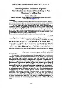
Material details As a part of on-going project, Inconel-625 plates were joined successfully through microwave hybrid heating by employing Inconel-625 powder as filler material. It is interesting to note that in contrast to most of the conventional welding techniques, welding in this work is carried out without the aid of any special fixtures and shielding gas. The chemical compositions of as-received Inconel-625 plate and Inconel-625 powder are shown in Table 1. The chemical composition of Inconel-625 powder shown in Table 1 was determined through electron probe micro analyzer (EPMA). Table 2 presents the mechanical properties of as-received Inconel-625 plate. Morphology of the Inconel-625 powder with average particle size of 50 mm used in this work is shown in Figure 1.
Figure 1. SEM view of Inconel-625 powder.
Development of joints The specimens required for experiments were cut from rolled Inconel-625 plate using wire electrical discharge machining (WEDM). Edge preparation for the pieces to be joined was done for square butt configuration. The interfacing surfaces of the Inconel-625 plates to be joined were cleaned with acetone. A thick paste of Inconel-625 filler powder was prepared by mixing it with epoxy resin Bisphenol A and Blumer 1450XX to facilitate the initial binding of loose powder particles and was applied to the joint interface. However, epoxy
4
Proc IMechE Part B: J Engineering Manufacture 00(0)
Figure 2. Sectional schematic of experimental setup. 1. incident microwaves; 2. alumina insulation; 3. susceptor; 4. refractory masking; 5. refractory brick; 6. rotary table; 7. base metal; 8. separator; 9. interface powder.
Table 3. Microwave processing parameters. Microwave frequency Exposure power Base metal Interface material Susceptor material Insulation Exposure time
2.45 GHz 900 W Commercial grade Inconel-625 plate Inconel-625 powder Coal powder Alumina fiber blocks 21 minutes approx.
resin does not affect the joint property as it couples with microwaves at much lower temperature and gets evaporated. Since coal is a very good absorber of microwaves at room temperature, it was used as a susceptor medium around the joint area. In order to avoid direct exposure of metallic plates to microwaves, Inconel-625 plates were masked with a refractory material. A thin graphite sheet was used as a separator between coal and Inconel-625 filler paste at the joint area to avoid possible intermixing of both elements. Figure 2 shows the schematic of experimental setup used in this study. Experiments were conducted in a low-cost 900 W multimode domestic microwave oven at 2.45 GHz frequency in a non-inert atmosphere. Various microwave processing parameters used in this work are indicated in Table 3. The photograph of Inconel-625 plates joined through microwave hybrid heating is shown in Figure 3.
Joint characterization Prior to characterization, the welded Inconel-625 plates were sectioned in a transverse plane normal to the joint axis using low-speed diamond cutter (Chennai Metco, Chennai, India) by maintaining continuous flow of coolant. The candidate surfaces were subjected to mechanical polishing as per the standard
metallographic procedure followed by etching with Marble’s reagent. XRD analysis of the joint was performed on BRUKER D8 Advance instrument with Cu–Ka radiation. The scan rate was maintained at 1°/ min with scan range from 20° to 100°. Joint microstructure was investigated through SEM (JSM-6380 LA; JEOL, Japan) equipped with energy dispersive X-ray detector. Vickers microhardness of the joint was examined on Omnitech microhardness tester (S. Auto, India). The microhardness indentations were obtained at various locations with a load of 50 g applied for dwell period of 10 s. Uniaxial tensile test was conducted on universal testing machine (Tinius Olsen, UK) to estimate tensile properties of the welded joints. The tensile strength of the joints was evaluated with a uniform strain rate of 0.008 mm/s at room temperature. Tensile specimens were machined as per ASTM E8 standard with gauge length 25 mm as shown in Figure 4. In order to investigate the flexural behavior of the microwave welded joints, standard 3-point bend tests were conducted on specimens prepared according to ASTM E190-92 guidelines. Figure 5 illustrates the schematic of 3-point bend test. The tests were conducted on UTM (UNITEK 9450; FIE, India) with a strain rate 0.01 mm/ s. Charpy V-notch impact test was performed using impact testing machine (FIE) on the sub-size specimens (Figure 6) prepared as per ASTM E23 guidelines.
Mechanism of joint formation The steps involved in joint formation are schematically illustrated in Figure 7. At 2.45 GHz frequency, interaction of bulk metal with microwaves at room temperature is restricted only to its surface due to very small skin depth. The skin depth of a material is defined as distance into the material at which the incident power reduces to 1/e (36.8%) of the surface value.16 Mathematically, skin depth is expressed by equation (1) as
Badiger et al.
5
Figure 3. (a) Photograph of Inconel-625 plates joined through microwave hybrid heating and (b) optical microscope image of the joint zone.
Figure 4. ASTM E8 standard tensile test specimen.
d=
rffiffiffiffiffiffiffiffiffi r pfm
ð1Þ
where d is the skin depth (mm), r is the resistivity (mO cm), f is the operating frequency (GHz), m is the magnetic permeability = mr 3 mo (H/m), mo is the absolute permeability = 4 3 p 3 1027 (H/m) and mr is the relative permeability.
The skin depth of any material depends on its resistivity, operating frequency and magnetic permeability. At an operating frequency of 2.45 GHz, it is possible to increase the skin depth of a material by changing the resistivity and magnetic permeability that are temperature-dependent variables. At room temperature, skin depth of nickel, the major component of Inconel-625, is calculated as 0.12 mm by substituting
6
Proc IMechE Part B: J Engineering Manufacture 00(0)
Figure 5. Schematic arrangement of 3-point bend test.
Figure 6. (a) ASTM E23 proportions of Charpy V-notch specimen and (b) Position of specimen during the test.
r = 8.707 3 1028 O m, f = 2.45 3 109 Hz and mr = 600 in equation (1).17 The calculated skin depth is approximately 330 times lesser than the size of Inconel625 powder particles used in this study, and hence direct exposure of Inconel-625 particles to microwave radiation results in surface heating and reflection of the incident microwaves takes place as shown in Figure 7(a). However, microwave hybrid heating technique is used to overcome this problem. In Figure 7(b), the powder particles in the interface region are shown with 0.12 mm skin depth at room temperature. The microwaves initially come in contact with coal which readily interacts with microwaves and gets heated up. This heat from coal is transferred to the powder particles via separator which is in direct contact with coal through conventional mode till the powder particles attain a critical temperature Tc. At this temperature, the skin depth of powder particles increases so as to facilitate direct interaction with microwaves as shown in Figure 7(c). Powder particles in the interface region couple
with microwaves and fusion of particles takes place (Figure 7(d)); at the same time, wetting of the joint interface occurs. Further heating results in diffusion of atoms from joint to the base metal and vice versa. With the seizure in microwave power, the diffusion process stops and the specimen cools down to room temperature resulting in solidified joint as shown in Figure 7(e).
Results and discussion Foregoing sections describe the observations and inferences made during the characterization of Inconel-625 welded joints, carried out in two phases, namely, metallurgical and mechanical characterization.
Metallurgical characterization XRD observations. XRD pattern obtained for the starting Inconel-625 powder is shown in Figure 8(a). The analysis of diffraction pattern and its comparison with
Badiger et al.
7
Figure 7. Steps involved in joint formation: (a) powder particles in the interface region subjected to direct exposure of microwaves at room temperature and microwaves getting reflected (b) coal powder gets heated through microwave radiation and transmits radiant heat to Inconel-625 powder (c) increased skin depth of Inconel-625 particles at critical temperature Tc (d) direct interaction of Inconel-625 powder with microwaves beyond critical temperature Tc and fusion of powder particles (e) solidified joint.
PCPDF database (reference: JCPDS file number 656291) indicate the presence of dominating peaks of Ni–Cr solid solution (g-phase) in face-centered cubic (FCC) matrix.Figure 8(b) shows the XRD pattern of the joint developed through microwave hybrid heating. XRD pattern clearly indicates the development of carbide, oxide and intermetallic phases along with the primary g-phase FCC matrix. The spectrum shows the presence of carbides Cr3C2, NbC and Fe1.86C0.14 corresponding to 2u values of 43.61°, 34.93° and 43.44°, respectively. Furthermore, the formation of oxide TiO2
is also observed at 2u value of 25.63°. Occurrence of intermetallics Cr2Ti6O15 and Ni8Nb corresponding to 2u values of 29.54° and 74.46°, respectively, is also observed. In addition, small traces of TiN are also encountered at 2u corresponding to 43.26°. Silva et al.6 have reported that occurrence of TiN in the fused metal supports the formation of niobium carbide. Since the melting point of TiN is much higher than Inconel-625 alloy, it does not dissolve in the molten pool and hence serves as nucleating agent for the formation of NbC. The formation of carbides is attributed to the strong
8
Proc IMechE Part B: J Engineering Manufacture 00(0)
Figure 9. SEM micrograph of microwave induced welded joint and base metal.
Figure 8. XRD patterns of (a) Inconel-625 powder and (b) Inconel-625 joint developed through microwave hybrid heating.
affinity of niobium and chromium with carbon at elevated temperatures. The equilibrium distribution coefficient of Nb in nickel-based alloys is less than unity (0.46); hence, it easily segregates into interdendritic region during solidification and produces niobium carbide.33 The formation of the observed oxides is attributed to the reaction of atmospheric oxygen with titanium at high temperatures. Development of intermetallic compounds is due to the fact that various alloying elements are found in free form in the starting powder; however during heating, these alloying elements react and combine with each other at high temperatures resulting in formation of intermetallic phases. Formation of intermetallic phases, carbides and oxides has a great impact on the dielectric properties of the material and contributes to better coupling of interface material with microwaves to raise the joint temperature. At this elevated temperature, fusion of the powder
Figure 10. SEM micrograph of fusion zone showing the precipitation of secondary eutectic phase.
in the interface region occurs and continued heating results in formation of molten pool in the joint interface. Furthermore, diffusion of atoms takes place between the interfacing surfaces and melt which indicates the significance of microwave heating process.
Observations of microstructure. Microstructure of the joint developed through microwave hybrid heating shown in Figure 9 indicates complete metallurgical bonding of the Inconel-625 powder particles with the base metal. It can be clearly seen that fusion zone, joint interface and the surrounding region are free from any visible interfacial cracks. Figure 10 shows magnified view of the fusion zone in which a cellular structure of grains with significant refinement is evident as a result of volumetric heating observed during the process. The microstructure also reveals the precipitation of secondary phases at the grain boundaries. As illustrated in
Badiger et al.
Figure 11. Different locations in fusion zone chosen for EDS analysis.
Figure 11, energy dispersive spectroscopy (EDS) analysis was carried out to estimate the chemical composition of some major elements at different locations (L1–L4) and the results are presented in Table 4. Further, the line analysis was also performed as illustrated in Figure 12(a) along the red line. Figure 12(b) shows the superposition of variation in the elemental composition over the SEM image. At position L1 in the interface region (Figure 11) and also from Figure 12(b), increase in compositions of nickel and chromium is observed. As revealed by XRD analysis, segregation of chromium at the joint interface leads to the formation of chromium carbide in this region. Furthermore, from Figure 12(b), it is evident that variation in niobium composition is uneven. At some places in the interior of the joint, niobium composition increases; however, this enrichment in niobium at the grain boundary has been observed to confirm to the characteristics of Laves phase as shown in Figure 10. Cieslak34 reported that during
9 solidification of Inconel-625 alloy, niobium depletes at the dendritic cores and precipitates into interdendritic regions as its distribution coefficient is less than unity. C/Nb ratio dictates the resulting structure of the solidified alloy depending on whether the ratio is high or low, leading to the formation of g+ Laves at low C/Nb ratios. The results observed at position L4 in Table 4 also show the enrichment in the amount of niobium. However, EDS analysis at grain boundary considered at location L3 indicates increase in the amount of molybdenum. As well as from Figure 12(b), it can be seen that composition of molybdenum is also increasing towards the interface region. Molybdenum at elevated temperature due to the affinity with carbon forms Mo2C in the interface region and also near the grain boundaries. However, the segregation of molybdenum is not intense when compared to niobium. It is interesting to note that, at location L2 there is depletion in the amount of Nb which is attributed to the partial dilution of Nb during microwave heating. This diluted Nb further leads to the formation of Laves phase and precipitates along the grain boundaries. Another observation made in this study is the presence of secondary rod-shaped Laves phase and cubeshaped precipitates in the fusion zone (Figure 13). Silva et al.6 reported that these cubic particles are rich in Nb, Ti, C and N. Additional work is, however, required to better understand the formation of these phases.
Mechanical characterization Observations of microhardness and porosity measurement. Microhardness indentations were obtained across the joint by maintaining a distance of 50 mm between successive indentations. Microhardness of the microwave-induced joint was measured in the fusion zone, interface and adjacent base metal regions. At each location, four indentations were obtained and
Figure 12. (a) Position at which line analysis is carried out indicating different zones in the welded specimen and (b) variation in elemental composition from base metal towards the fusion zone.
10
Proc IMechE Part B: J Engineering Manufacture 00(0)
Table 4. Chemical composition observed in microstructure of the developed joint (wt.%). Element
C N Ti Cr Fe Co Nb Mo Ni
Location L1
L2
L3
L4
4.44 1.47 0.12 22.36 3.46 0.34 2.166 2.293 Bal.
3.18 0.02 0.11 19.97 4.34 0.23 1.65 8.17 Bal.
3.91 2.75 0.16 20.28 3.91 0.21 7.14 10.38 Bal.
4.53 1.51 0.23 21.21 4.38 0.24 8.23 8.16 Bal.
Figure 13. Occurrence of rod-shaped and cuboid-shaped secondary phases.
the mean value was considered to plot the variation profile. Figure 14(a) shows the SEM micrographs of indentations in the fusion zone, whereas indentations in the interface and base metal regions are illustrated in Figure 14(b). Variation in the microhardness profile is plotted as shown in Figure 15. However, it is seen that hardness increases from center of the joint towards the interface and is observed to be maximum as it approaches interface region. This increased hardness in the interface region is attributed to the formation of chromium and molybdenum carbides as revealed by XRD and EDS analyses. Due to the dilution of matrix during microwave heating, the elements from the matrix diffuse into the interface region and react with carbon to form carbides along the joint interface. Furthermore, formation of intermetallic phases also contributes towards increasing the hardness. Maximum hardness value observed at the joint interface was 375 HV, whereas average Vickers microhardness value observed in the fusion zone was 245 6 20 HV. Hardness of the fusion zone is observed to be approximately same as that of base metal which is an indication of a sound joint. However, it is interesting to note that joint hardness values obtained with microwave-induced welding are similar to the hardness values as that obtained with
TIG welded joints. Porosity of the microwave-induced joint was measured using Biovis Materials Plus software and was observed to be 0.7%. This obtained low value of porosity is attributed to the volumetric heating during microwave hybrid heating process. Volumetric heating results in uniform heating with reduced porosity throughout the weld region which is difficult to obtain with conventional techniques.25
Observations from tensile test. A view of microwave welded Inconel-625 standard tensile specimens is shown in Figure 16. Average UTS was recorded as 375 MPa with an average elongation of 9.2% which signifies a good metallurgical bonding between interface powder and base metal. However, the observed tensile strength in this work is higher by 15% than that reported earlier wherein welding of Inconel-625 alloy has been carried out using nickel interface powder.27 A typical stress–strain curve obtained for one of the tensile specimens is illustrated in Figure 17. The UTS was recorded as 375 MPa and a percentage elongation of 9.2% was observed. The first phase marked by segment 0–A in Figure 17 indicates the region of elastic deformation in which the specimen
Badiger et al.
11
Figure 14. Typical SEM images showing microhardness indentations in (a) weld zone and (b) joint interface and base metal.
Figure 15. Vickers microhardness profile obtained across the developed joint.
Figure 16. Tensile test specimens prepared as per ASTM E8 standard.
exhibits a linear elastic behavior. Point A being the yield point of the material determined by 0.2% offset strain method was recorded as 39.2 MPa. However, second phase between points A and B corresponds to the region of plastic deformation. During plastic
Figure 17. Typical stress–strain curve obtained from tensile test.
12
Proc IMechE Part B: J Engineering Manufacture 00(0)
Figure 18. Photograph of fractured specimen showing fracture in the joint zone.
Figure 19. SEM micrograph showing elongated grains in base metal near the interface region.
deformation, as the applied load continues to increase, material is subjected to strain hardening and the loadbearing capacity of the material also goes on increasing which is attributed to the movement of dislocations. Furthermore, it is observed during the tensile test that specimens were fractured in the fusion zone as shown in Figure 18. This is due to the fact that during plastic deformation, the dislocation movement is restricted by the presence of Laves phase at the grain boundaries as revealed from microstructure study. As the plastic deformation in the weld zone continues, more and more dislocations are pushed towards the grain boundaries so that piling up of dislocations takes place. Thus, the shear stress is built up at the head of this pile of dislocations which squeezes them together. When this shear stress at the head of dislocation pile up reaches a critical value, the dislocations are further pushed closer to an extent that they combine with each other to form microcracks at the brittle grain boundary.35 The growth of cracks persists with continued plastic deformation up to point B in Figure 17. Eventually at point B, which is the UTS of the specimen, the loadbearing capacity of material is dominated by moderate reduction in cross-sectional area and no further deformation is possible. Additional increment in load results in rapid propagation of these cracks leading to fracture of the specimen as depicted by segments B and C of stress–strain curve. It can be clearly seen from Figure 17 that the material has undergone a
considerable amount of plastic deformation prior to its failure which is attributed to the ductility of the matrix phase. The occurrence of plastic deformation is further confirmed from SEM micrograph of the surface near the interface in Figure 19 wherein the elongation of grains can be clearly seen in the direction of the applied load. However, this plastic deformation is seized due to the presence of Nb-rich Laves phase at the grain boundaries. Further it is evident from microhardness profile that, although hardness at the joint interface is marginally greater than that of fusion zone, the effect of crack growth and propagation is predominant at the grain boundaries in the fusion zone where presence of Laves phase is seen. Fractured specimens after the tensile test were further subjected to fractography study using SEM. Careful observation of SEM micrographs of fractured specimen in Figure 20 reveals that the fracture has occurred in combination of ductile and brittle modes. Ductile fracture is characterized by fibrous pattern with dimples as it is clearly seen at many locations in Figure 20. Typically, failure commences with the formation of minute voids around small inclusions or preexisting discontinuities which then grow and merge leading to the formation of cracks that propagate with the application of load, resulting in fracture of the specimen. However in Figure 20, tear ridges with river markings as a result of shear failure are also seen which signify a cleavage fracture. The occurrence of cleavage fracture is attributed to the initiation of a crack in the brittle carbide at the grain boundary.35 The presence of carbides and intermetallic phases at the grain boundaries serves as the sources for crack initiation. When a crack moves through a crystal along number of parallel planes, it results in a series of plateaus and connecting ledges, leading to the formation of river markings. Therefore, it is evident from above discussion that mixed mode type of a fracture takes place. The comparative results of similar type joints developed through TIG welding process have been studied. The strength obtained with TIG welded joints is approximately 50% of the base metal strength and 10% higher than that of the joints produced using microwave hybrid heating. This decreased strength in microwave-induced joints is attributed to the presence of chromium carbide in the interface region. Another reason for increased strength in TIG welded joints could be due to the form of filler material used in the joint interface. The filler material in TIG welding is in the form of wire which is melted
Badiger et al.
13
Figure 20. SEM micrographs of fractured surfaces showing mixed mode type fracture.
Figure 21. ASTM E190 standard specimens for 3-point bend test.
and deposited directly on to the joint interface, whereas in microwave-induced welding, starting filler material is in the form of powder and there exists a possibility that few powder particles in the joint may not fuse completely, thus contribute to reduce the strength of the joint.
Observations from 3-point bend test. Three replicates of bending specimens were machined based on ASTM E190-92 guidelines with dimensions 100 3 20 3 4 mm3 to assess the flexural strength of the microwave welded joints. Figure 21 shows the photographs of the bending specimens. A typical load–displacement characteristic observed during the flexural study is illustrated in Figure 22. The load–displacement curve is presented in three different elements as shown in Figure 22 for the displacement up to 0.15 mm (stage I), displacement between 0.15 and 0.5 mm (stage II) and displacement beyond 0.5 mm (stage III) till the complete fracture of the specimen. In stage I, up to a load of 0.628 kN, the
Figure 22. Typical load–displacement curve obtained during 3point bend test.
welded joint exhibits a uniform load–displacement behavior. During this stage, the ductile phase in the joint deforms elastically under the action of applied load and layers below the neutral axis get elongated under tensile stresses. However at the same time, layers above the neutral axis also deform elastically and are subjected to compressive stresses. A deviation in the load–displacement curve (stage II) is observed when loading is increased beyond 0.628 kN which is the initiation of plastic state. The corresponding deformation during this stage becomes plastic and increases with increasing load up to 3.5 kN which is the maximum load experienced by the welded joint. As the load increases from 0.628 kN, the fibers below the neutral axis deform under the tensile stresses and lead to the formation of microcracks. Development of microcracks is also attributed to the presence of brittle Laves phase at grain boundaries which serves as the source for
14
Proc IMechE Part B: J Engineering Manufacture 00(0)
Figure 23. Photograph showing the propagated crack in the fractured specimen.
Figure 24. SEM micrograph of fractured specimen after 3-point bend test showing the growth of cracks in multiple directions.
initiation of microcracks. Flexural strength at the maximum load of 3.5 kN is calculated as 377 MPa. Further loading causes opening of the microcracks under tensile stresses and a sudden drop in the load–displacement characteristic is observed as indicated by stage III in Figure 22. During this stage, a sharp decrease in the load accompanied by a small increase in the magnitude of displacement can be seen. This is attributed to the growth of microcracks and their rapid propagation through weld cross section which result in a complete fracture of the specimen. Figure 23 shows fractured surface of the microwave-induced joint subjected to 3-point bend test. In order to investigate the mode of fracture, fractography analysis of 3-point bend test welded specimen was carried out using SEM. Figure 24 shows the SEM micrograph of the fractured specimen. Initially, the load is taken up by the nickel-based ductile phase and later with increased loading the welded joint undergoes a severe plastic deformation leading to the development of microcracks. Brittle metallic phases at the grain boundaries act as location for crack initiation. In addition, tensile stress induced in the welded joint also promotes growth and propagation of these cracks. As a result, the cracks grow in multiple directions and propagate through the cross section of the weld. However, it is interesting to note that flexural strength of the microwave-induced joints is almost equal to UTS of the specimens tested under tensile loading. Furthermore, specimens during 3-point bend test experienced a large
Figure 25. Welded Charpy V-notch impact test specimens.
amount of deformation prior to fracture and thus lead to a mixed mode fracture as seen from the micrograph shown in Figure 24. It is also observed from EDS spectra that the hard particles of carbides are mostly concentrated at the grain boundaries. These hard particles do not allow the material to flow plastically during loading and thus shearing action at the joint zone, leading to sudden failure of the material at the joint area. The dominance of brittle failure in joint zone could be in the area where total melting of the powder particles in sandwich layer during microwave irradiation and subsequent re-solidification occurs. Observations from impact test. The microwave-induced welded joints were further subjected to impact test to investigate the failure of joints under the application of impact loads. The sub-sized Charpy specimens (55 3 10 3 5 mm3) were prepared out of the welded plates based on ASTM E23 guidelines. Notches were machined such that fractures appeared in the welded zones as shown in Figure 25. It is observed that impact specimens experience a severe fracture along the fusion zone, and the average impact toughness of microwaveinduced joints was estimated to be 18 J which is much lower as compared to that of base metal (92 J). This lower energy absorption is attributed to the segregation
Badiger et al.
15 2.
3.
4.
Figure 26. SEM micrograph showing fractured surface of impact tested specimen.
of niobium at the grain boundaries and formation of niobium carbide as revealed from EDS analysis. Li et al.1 reported that toughness of the welded joints is closely related to microstructure which is attributed to inhomogeneity in the fusion zone and niobium and molybdenum segregation in the interdendritic regions. Investigations reveal that Laves phase presents harmful effects to the strength of the joint. Xu et al.7 observed that occurrence of Laves phase largely influences the fracture mechanism by providing favorable sites for excessive microvoid initiation and growth of macroscopic cracks. SEM micrograph of fractured surface of Charpy V-notch specimen shown in Figure 26 illustrates that the microwave-induced joint has undergone a complete brittle fracture which consists of cleavages that lead to shear failure of the joint. Also, it is observed that a few regions in the fractured specimen show tiny dimples which reveal that the joint exhibits very small plastic deformation attributed to the energy absorbed by the specimen prior to failure. Furthermore, the obtained values of impact energy absorbed are closely related to modulus of toughness in stress–strain diagram shown in Figure 17.
Conclusion In this work, joining of Inconel-625 plates with Inconel625 powder as interface material is achieved using microwave hybrid heating technique. The characterization of these joints is done using different techniques. The following conclusions can be drawn from this work: 1.
Joining of Inconel-625 plates through microwave energy has been carried out successfully using Inconel-625 powder as the interface material. Complete metallurgical bonding of the interface powder with base metal is achieved.
5.
6.
7.
XRD study reveals the formation of chromium carbide at the interface between fusion zone and base metal. Formation of niobium carbide is observed at the grain boundaries in the fusion zone. Also, the development of TiN, Ni8Nb and Cr2Ti6O15 intermetallic phases is detected. The microstructure of the joint shows a cellular structure with refined grains in fusion zone which is attributed to volumetric heating observed in microwave processing. EDS study reveals the niobium-rich Laves phase at the grain boundaries. Average Vickers microhardness of the joint in the fusion zone is observed to be 245 6 20 HV, whereas maximum hardness value recorded at the joint interface is 375 HV and the observed porosity in the joint zone is 0.7%. Average UTS of the joint is found to be 375 MPa with an average elongation of 9.2%. Measured UTS of the joint is approximately 40% of the base metal strength. Maximum flexural strength is calculated as 377 MPa and average impact toughness of the welded joints was observed to be 18 J. The specimen exhibits relatively large amount of plastic deformation during tensile test prior to fracture, which indicates that the developed joint is sufficiently ductile. However, precipitation of carbides at the interface restricts the further plastic deformation of the joint. Fractography studies of tensile and 3-point bend tests reveal the mixed mode type of fracture, and as contrast, impact fractured surfaces indicate a complete brittle fracture.
Declaration of conflicting interests The author(s) declared no potential conflicts of interest with respect to the research, authorship and/or publication of this article. Funding The author(s) received no financial support for the research, authorship and/or publication of this article. References 1. Li G, Huang J and Wu Y. An investigation on microstructure and properties of dissimilar welded Inconel 625 and SUS 304 using high-power CO2 laser. Int J Adv Manuf Tech 2015; 76(5–8): 1203–1214. 2. Rai SK, Kumar A, Shankar V, et al. Characterization of microstructures in Inconel 625 using X-ray diffraction peak broadening and lattice parameter measurements. Scripta Mater 2004; 51(1): 59–63. 3. Budinger DE. Microwave brazing process. US Patent 0290137, 2008. 4. Rajani HZ and Mousavi SA. The effect of explosive welding parameters on metallurgical and mechanical interfacial features of Inconel 625/plain carbon steel bimetal plate. Mat Sci Eng A: Struct 2012; 556: 454–464.
16 5. Kondapalli SP, Chalamalasetti SR and Damera NR. Optimizing pulsed current micro plasma arc welding parameters to maximize ultimate tensile strength of Inconel 625 nickel alloy using response surface method. Int J Eng Sci Tech 2011; 3(6): 226–236. 6. Silva CC, de Miranda HC, Motta MF, et al. New insight on the solidification path of an alloy 625 weld overlay. J Mater Res Technol 2013; 2(3): 228–237. 7. Xu F, Lv Y, Liu Y, et al. Microstructural evolution and mechanical properties of Inconel 625 alloy during pulsed plasma arc deposition process. J Mater Sci Technol 2013; 29(5): 480–488. 8. Ramkumar KD, Sridhar R, Periwal S, et al. Investigations on the structure—property relationships of electron beam welded Inconel 625 and UNS 32205. Mater Design 2015; 68: 158–166. 9. Wilson ILW, Gourley RG, Walkosak RM, et al. The effect of heat input on microstructure and cracking in alloy 625 weld overlays. In: Loria EA (ed.) Superalloys 718, 625 and various derivatives. The Minerals, Metals and Materials Society (TMS), 1991, pp.735–747, http:// iweb.tms.org/SUP/superalloysvd1991/01-173x-735.pdf 10. Song KH and Nakata K. Mechanical properties of friction-stir-welded Inconel 625 alloy. Mater Trans 2009; 50(10): 2498–2501. 11. Janicki D. Welding of Inconel 625 using a direct diode laser. Adv Mat Res 2014; 1036: 331–336. 12. Oghbaei M and Mirzaee O. Microwave versus conventional sintering: a review of fundamentals, advantages and applications. J Alloy Compd 2010; 494(1): 175–189. 13. Singh S, Gupta D and Jain V. Recent applications of microwaves in materials joining and surface coatings. Proc IMechE, Part B: J Engineering Manufacture 2016; 230(4): 603–617. 14. Roy R, Agrawal D, Cheng J, et al. Full sintering of powdered-metal bodies in a microwave field. Nature 1999; 399(6737): 668–670. 15. Prabhu G, Chakraborty A and Sarma B. Microwave sintering of tungsten. Int J Refract Met Hard Mater 2009; 27(3): 545–548. 16. Mondal A, Agrawal D and Upadhyaya A. Microwave heating of pure copper powder with varying particle size and porosity. J Microwave Power EE 2008; 43(1): 5–10. 17. Gupta D and Sharma AK. Development and microstructural characterization of microwave cladding on austenitic stainless steel. Surf Coat Tech 2011; 205: 5147–5155. 18. Sharma AK and Gupta D. On microstructure and flexural strength of metal–ceramic composite cladding developed through microwave heating. Appl Surf Sci 2012; 258(15): 5583–5592. 19. Zafar S and Sharma AK. Development and characterisations of WC–12Co microwave clad. Mater Charact 2014; 96: 241–248. 20. Chandrasekaran S, Basak T and Ramanathan S. Experimental and theoretical investigation on microwave
Proc IMechE Part B: J Engineering Manufacture 00(0)
21.
22. 23.
24.
25.
26.
27.
28.
29.
30.
31.
32.
33.
34. 35.
melting of metals. J Mater Process Tech 2011; 211(3): 482–487. Singh S, Gupta D and Jain V. Microwave melting and processing of metal–ceramic composite castings. Proc IMechE, Part B: J Engineering Manufacture. Epub ahead of print 1 September 2016. DOI: 10.1177/ 0954405416666900. Barmatz M, Jackson W and Radtke PR. Microwave technique for brazing materials. US Patent 6054693, 2000. Siores E and Do Rego D. Microwave applications in materials joining. J Mater Process Tech 1995; 48(1): 619– 625. Sharma AK, Srinath MS and Kumar P. Microwave joining of metallic materials. Indian Patent 1994/Del/2009, 2009. Srinath MS, Sharma AK and Kumar P. A novel route for joining of austenitic stainless steel (SS-316) using microwave energy. Proc IMechE, Part B: J Engineering Manufacture 2011; 225(7): 1083–1091. Srinath MS, Sharma AK and Kumar P. Investigation on microstructural and mechanical properties of microwave processed dissimilar joints. J Manuf Process 2011; 13: 141–146. Badiger RI, Narendranath S and Srinath MS. Joining of Inconel-625 alloy through microwave hybrid heating and its characterization. J Manuf Process 2015; 18: 117–123. Bansal A, Sharma AK, Das S, et al. On microstructure and strength properties of microwave welded Inconel 718/stainless steel (SS-316L). Proc IMechE, Part L: J Materials Design and Applications. Epub ahead of print 1 June 2015. DOI: 10.1177/1464420715589206. Bansal A, Sharma AK, Kumar P, et al. Structure–property correlations in microwave joining of Inconel 718. JOM 2015; 67(9): 2087–2098. Bansal A, Sharma AK, Kumar P, et al. Investigation on microstructure and mechanical properties of the dissimilar weld between mild steel and stainless steel-316 formed using microwave energy. Proc IMechE, Part B: J Engineering Manufacture 2016; 230(3): 439–448. Chandrasekaran S, Srinivasan R and Basak T. Microwave material processing—a review. AIChE J 2012; 58: 330–363. Thostenson ET and Chou TW. Microwave processing: fundamentals and applications. Compos Part A: Appl S 1999; 30(9): 1055–1071. DuPont JN, Robino CV and Marder AR. Modelling mushy zones in welds of multicomponent alloys: implications for solidification cracking. Sci Technol Weld Joi 1999; 4(1): 1–14. Cieslak MJ. The welding and solidification metallurgy of alloy 625. Weld J 1991; 70(2): 49s–56s. Dieter GE. Mechanical metallurgy. SI metric ed. London: McGraw-Hill Book Company Ltd, 1988, pp.254–259.