Conversely, a channel is referred to as slow fading if the signaling rate is .... where x(t) is the data signal, g(t) is the pseudonoise (PN) spreading code, and Ï is.
Mitigating the Degradation Effects of Fading Channels by Bernard Sklar Introduction This article emphasizes so-called Rayleigh fading, primarily in the UHF band, that affects mobile systems such as cellular and personal communication systems (PCS). The major elements that contribute to fading and their degradation effects in a communication channel are briefly summarized. Emphasis is then placed on methods for mitigating the degradation. Two examples of specific mitigation techniques are examined: the Viterbi equalizer implemented in the Global System for Mobile (GSM) Communications, and the Rake receiver used in CDMA systems built to meet Interim Standard-95 (IS-95).
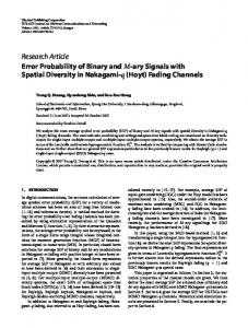
Fading Phenomena in Brief The block diagram in Figure 1 serves to organize the key manifestations that a fading channel can exhibit [1]. It starts by categorizing large-scale fading, which represents the average signal-power attenuation or the path loss due to motion over large areas. In Figure 1, the large-scale fading manifestation is shown in blocks 1, 2, and 3. This phenomenon is affected by prominent terrain contours (hills, forests, billboards, clumps of buildings, and so on) between the transmitter and the receiver. Small-scale fading refers to the dramatic changes in signal amplitude and phase that can be experienced as a result of small changes (as small as a half wavelength) in the spatial positioning between a receiver and a transmitter. As indicated in Figure 1 blocks 4, 5, and 6, small-scale fading manifests itself in two mechanisms: time-spreading of the signal (or signal dispersion) and time-variant behavior of the channel. For mobile-radio applications, the channel is time-variant because motion between the transmitter and the receiver results in propagation path changes. The rate of change of these propagation conditions accounts for the fading rapidity [1]. Examining these manifestations involves two views: time and frequency, as indicated in Figure 1 blocks 7, 10, 13, and 16. Two degradation categories can be defined for dispersion: frequency-selective fading and flatfading, as listed in blocks 8, 9, 11, and 12. Two degradation categories can be defined for fading rapidity: fast fading and slow fading, as listed in blocks 14, 15, 17, and 18.
Figure 1 Fading channel manifestations.
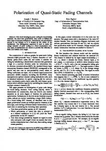
A model of the fading channel consists of four functions (see Figure 2). In Figure 2a, a multipath-intensity profile, S(τ), is plotted versus time delay, τ. Knowledge of S(τ) helps answer the question, “For a transmitted impulse, how does the average received power vary as a function of time delay, τ?” For a single transmitted impulse, the time, Tm, between the first and last received signal components represents the maximum excess delay, during which the multipath signal power falls to some threshold level below that of the strongest component. Figure 2b shows the function │R(∆f)│, designated a spaced-frequency correlation function; it is the Fourier transform of S(τ). The function R(∆f) represents the correlation between the channel’s response to two signals as a function of the frequency difference between the two signals. Knowledge of R(∆f) helps answer the question, “What is the correlation between received signals that are spaced in frequency ∆f = f1 - f2?” The coherence bandwidth, f0, is a statistical measure of the range of frequencies over which the channel passes all spectral components with approximately equal gain and linear phase. Thus, the coherence bandwidth represents a frequency range over which frequency components have a strong potential for amplitude correlation. Note that f0 and Tm are reciprocally related (within a multiplicative constant). As an approximation, it is possible to say that 2
Mitigating the Degradation Effects of Fading Channels
f0 ≈
1 Tm
(1)
A more useful measurement of delay spread is most often characterized in terms of the root mean squared (rms) delay spread, στ [2]. A popular approximation of f0 corresponding to a bandwidth interval having a correlation of at least 0.5 is as follows: f0≈
1 5σ τ
(2)
Figure 2c shows the function R(∆t), designated the spaced-time correlation function; it is the autocorrelation function of the channel’s response to a sinusoid. This function specifies the extent to which there is correlation between the channel’s response to a sinusoid sent at time t1 and the response to a similar sinusoid sent at time t2, where ∆t = t2 - t1. The coherence time, T0, is a measure of the expected time duration over which the channel’s response is essentially invariant. Figure 2d shows a Doppler power spectral density, S(ν), plotted as a function of Doppler-frequency shift, ν; it is the Fourier transform of R(∆t). The sharpness and steepness of the boundaries of the Doppler spectrum are due to the sharp upper limit on the Doppler shift produced by a vehicular antenna traveling among a dense population of stationary scatterers. The largest magnitude of S(ν) occurs when the scatterer is directly ahead of the moving antenna platform or directly behind it. The width of the Doppler power spectrum is referred to as the spectral broadening or Doppler spread, denoted by fd, and sometimes called the fading bandwidth of the channel. Note that the Doppler spread, fd, and the coherence time, T0, are reciprocally related (within a multiplicative constant). The time required to traverse a distance λ/2 (approximately the coherence time) when traveling at a constant velocity V is as follows: T0 ≈
0.5 λ/2 = V fd
Mitigating the Degradation Effects of Fading Channels
(3)
3
Figure 2 Relationships among the channel correlation functions and power density functions.
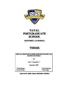
Degradation Categories in Brief Degradation categories are reviewed here in the context of Figure 3, which summarizes small-scale fading mechanisms, degradation categories, and their effects. When viewed in the time-delay domain, a channel is said to exhibit frequency-selective fading if Tm > Ts (the delay time is greater than the symbol time). This condition occurs whenever the received multipath components of a symbol extend beyond the symbol’s time duration, thus causing channel-induced intersymbol interference (ISI). Viewed in the time-delay domain, a channel is said to exhibit frequency nonselective or flat fading if Tm < Ts. In this case, all of the received multipath components of a symbol arrive within the symbol time duration; hence, the components are not resolvable. Here there is no channel-induced ISI distortion, since the signal time-spreading does not result in significant overlap among neighboring received symbols. There is still performance degradation, since the 4
Mitigating the Degradation Effects of Fading Channels
unresolvable phasor components can add up destructively to yield a substantial reduction in signal-to-noise ratio (SNR).
Figure 3 Small-scale fading: mechanisms, degradation categories, and effects.
When viewed in the frequency domain, a channel is referred to as frequency selective if f0 < 1/Ts ≈ W, where the symbol rate, 1/Ts, is nominally taken to be equal to the signal bandwidth W. Flat-fading degradation occurs whenever f0 > W. Here, all of the signal’s spectral components will be affected by the channel in a similar manner (for example, fading or no fading). To avoid ISI distortion caused by frequency-selective fading, the channel must be made to exhibit flat fading by ensuring that the coherence bandwidth exceeds the signaling rate. When viewed in the time domain, a channel is referred to as fast fading whenever T0 < Ts, where T0 is the channel coherence time and Ts is the symbol time. Fast fading describes a condition in which the time duration that the channel behaves in a correlated manner is short compared to the time duration of a symbol. Therefore, it can be expected that the fading character of the channel will change several times during the time that a symbol is propagating. This leads to distortion of the baseband pulse shape, because the received signal’s components are not all highly correlated throughout time. Hence, fast fading can cause the baseband pulse to be Mitigating the Degradation Effects of Fading Channels
5
distorted, resulting in a loss of SNR that often yields an irreducible error rate. Such distorted pulses typically cause synchronization problems, such as failure of phaselocked-loop (PLL) receivers. Viewed in the time domain, a channel is generally referred to as introducing slow fading if T0 > Ts. Here, the time duration that the channel behaves in a correlated manner is long compared to the symbol time. Thus, one can expect the channel state to remain virtually unchanged during the time that a symbol is transmitted. When viewed in the Doppler-shift domain, a channel is referred to as fast fading if the symbol rate, 1/Ts, or the signal bandwidth, W, is less than the fading rate, 1/T0 or fd. Conversely, a channel is referred to as slow fading if the signaling rate is greater than the fading rate. In order to avoid signal distortion caused by fast fading, the channel must be made to exhibit slow fading by ensuring that the signaling rate exceeds the channel fading rate.
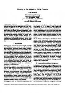
Mitigating the Degradation Effects of Fading Figure 4 highlights three major performance categories in terms of bit-error probability, PB, versus Eb/N0. The leftmost exponentially shaped curve highlights the performance that can be expected when using any nominal modulation scheme in AWGN interference. Observe that at a reasonable Eb/N0 level, good performance can be expected. The middle curve, referred to as the Rayleigh limit, shows the performance degradation resulting from a loss in Eb/N0 that is characteristic of flat fading or slow fading when there is no line-of-sight signal component present. The curve is a function of the reciprocal of Eb/N0 (an inverse-linear function), so for practical values of Eb/N0, performance will generally be “bad.” In the case of Rayleigh fading, parameters with overbars are often introduced to indicate that an average is being taken over the “ups” and “downs” of the fading experience. Therefore, one often sees such bit-error probability plots with averaged parameters denoted by PB and Eb N 0 . This notation emphasizes the fact that the fading channel has memory; thus, received samples of the signal are correlated to one another in time. Therefore, when producing such error-probability plots for a fading channel, one needs to examine the process over a window of time that is much larger than the channel coherence time. The curve that reaches an irreducible error-rate level, sometimes called an error floor, represents “awful” performance, where the bit-error probability can level off at values nearly equal to 0.5. This shows the severe performance degrading effects that are possible with frequencyselective fading or fast fading.
6
Mitigating the Degradation Effects of Fading Channels
If the channel introduces signal distortion as a result of fading, the system performance can exhibit an irreducible error rate at a level higher than the desired error rate. In such cases, no amount of Eb/N0 will help achieve the desired level of performance, and the only approach available for improving performance is to use some form of mitigation to remove or reduce the signal distortion. The mitigation method depends on whether the distortion is caused by frequency-selective fading or fast fading. Once the signal distortion has been mitigated, the PB versus Eb/N0 performance can transition from the “awful” category to the merely “bad” Rayleigh-limit curve. Next, it is possible to further ameliorate the effects of fading and strive to approach AWGN system performance by using some form of diversity to provide the receiver with a collection of uncorrelated replicas of the signal, and by using a powerful error-correction code.
Figure 4 The good, the bad, and the awful.
Mitigating the Degradation Effects of Fading Channels
7
In Figure 5, several mitigation techniques are listed for combating the effects of both signal distortion and loss in SNR; the figure can serve as a guide to indicate which technique is best suited for ameliorating the degradation due to various fading effects. The mitigation approaches to be used when designing a system should be considered in two basic steps: 1.
Choose the type of mitigation to reduce or remove any distortion degradation.
2.
Choose a diversity type that can best approach AWGN system performance.
Figure 5 Basic mitigation types. Mitigation to Combat Frequency-Selective Distortion
Equalization can mitigate the effects of channel-induced ISI brought on by frequency-selective fading. That is, it can help modify system performance described by the curve that is “awful” in Figure 4 to the one that is merely “bad.” The process of equalizing for mitigating ISI effects involves using methods to gather the dispersed symbol energy back into its original time interval. In effect, an equalizer is an inverse filter of the channel. If the channel is frequency selective, the equalizer enhances the frequency components with small amplitudes and attenuates those with large amplitudes. The goal is for the combination of channel and equalizer filter to provide a flat composite-received frequency response and linear phase [2]. Because in a mobile system the channel response varies with time, 8
Mitigating the Degradation Effects of Fading Channels
the equalizer filter must also change or adapt to the time-varying channel characteristics. Such equalizer filters are therefore adaptive devices that accomplish more than distortion mitigation; they also provide diversity. Since distortion mitigation is achieved by gathering the dispersed symbol’s energy back into the symbol’s original time interval so that it doesn’t hamper the detection of other symbols, the equalizer is simultaneously providing the receiver with symbol energy that would otherwise be lost. The decision feedback equalizer (DFE) has a feedforward section that is a linear transversal filter [2] whose stage length and tap weights are selected to coherently combine virtually all of the current symbol’s energy. The DFE also has a feedback section that removes energy remaining from previously detected symbols [2–5]. The basic idea behind the DFE is that once an information symbol has been detected, the ISI that it induces on future symbols can be estimated and subtracted before the detection of subsequent symbols. A maximum-likelihood sequence estimation (MLSE) equalizer tests all possible data sequences (rather than detecting each received symbol by itself) and chooses the data sequence that is the most probable of all the candidates. The MLSE equalizer was first proposed by Forney [6] and implemented by using the Viterbi decoding algorithm [7]. The MLSE is optimal in the sense that it minimizes the probability of a sequence error. Because the Viterbi decoding algorithm is typically used in the implementation of the MLSE equalizer, this device is often referred to as the Viterbi equalizer. This article later illustrates the adaptive equalization performed in the Global System for Mobile (GSM) Communications using the Viterbi equalizer. Direct-sequence spread-spectrum (DS/SS) techniques can be used to mitigate frequency-selective ISI distortion because the hallmark of spread-spectrum systems is their capability of rejecting interference, and ISI is a type of interference. Consider a DS/SS binary phase-shift keying (PSK) communication channel comprising one direct path and one reflected path. Assume that the propagation from transmitter to receiver results in a multipath wave that is delayed by τ compared to the direct wave. The received signal, r(t), neglecting noise, can be expressed as follows: r(t) = Ax(t)g(t)cos(2πfct) + αAx(t-τ)g(t-τ)cos(2πfct + θ)
(4)
where x(t) is the data signal, g(t) is the pseudonoise (PN) spreading code, and τ is the differential time delay between the two paths. The angle θ is a random phase, assumed to be uniformly distributed in the range (0, 2π), and α is the attenuation of Mitigating the Degradation Effects of Fading Channels
9
the multipath signal relative to the direct path signal. The receiver multiplies the incoming r(t) by the code g(t). If the receiver is synchronized to the direct path signal, multiplication by the code signal yields the following: r(t)g(t) = Ax(t)g2(t)cos(2πfct) + αAx(t-τ)g(t)g(t-τ)cos(2πfct + θ)
(5)
where g2(t) = 1. If τ is greater than the chip duration, then │∫g(t)g(t-τ)dt│.│∫g2(t)dt│
(6)
over some appropriate interval of integration (correlation). Thus, the spreadspectrum system effectively eliminates the multipath interference by virtue of its code-correlation receiver. Even though channel-induced ISI is typically transparent to DS/SS systems, such systems suffer from the loss in energy contained in the multipath components rejected by the receiver. The need to gather this lost energy belonging to a received chip was the motivation for developing the Rake receiver [8–10]. The Rake receiver dedicates a separate correlator to each multipath component (finger), and coherently adds the energy from each finger by selectively delaying each (the earliest component gets the longest delay) so that they can all be coherently combined. A channel that is classified as flat fading can occasionally exhibit frequencyselective distortion when the null of the channel’s frequency-transfer function occurs at the center of the signal band. The use of DS/SS is a practical way of mitigating such distortion because the wideband SS signal can span many lobes of the selectively faded channel frequency response. Hence, a great deal of pulse energy is passed by the scatterer medium, in contrast to the channel-nulling effect on a relatively narrowband signal [11]. The ability of the signal spectrum to span over many lobes of the frequency-selective channel transfer function is the key to how DS/SS signaling can overcome the degrading effects of a multipath environment. This requires the spread-spectrum bandwidth, Wss (or the chip rate, Rch), to be greater than the coherence bandwidth, f0. The larger the ratio of Wss to f0, the more effective the mitigation. A time-domain view of such mitigation can be similarly described. That is, to resolve multipath components requires that the spread-spectrum signal dispersion be greater than a chip time. Frequency-hopping spread-spectrum (FH/SS) can be used as a technique to mitigate the distortion caused by frequency-selective fading, provided that the hopping rate is at least equal to the symbol rate. Compared to DS/SS, mitigation takes place through a different mechanism. FH receivers avoid the degradation effects due to multipath by rapidly changing in the transmitter carrier-frequency 10
Mitigating the Degradation Effects of Fading Channels
band, thus avoiding the interference by changing the receiver band position before the arrival of the multipath signal. Orthogonal frequency-division multiplexing (OFDM) can be used for signal transmission in frequency-selective fading channels to avoid the use of an equalizer by lengthening the symbol duration. The approach is to partition (demultiplex) a high symbol-rate sequence into N symbol groups, so that each group contains a sequence of a lower symbol rate (by the factor 1/N) than the original sequence. The signal band is made up of N orthogonal carrier waves, and each one is modulated by a different symbol group. The goal is to reduce the symbol rate (signaling rate), W ≈ 1/Ts, on each carrier to be less than the channel’s coherence bandwidth f0. OFDM, originally referred to as Kineplex, is a technique that has been implemented in the United States in mobile radio systems [12], and has been chosen by the European community, under the name Coded OFDM (COFDM), for high-definition television (HDTV) broadcasting [13]. Pilot signal is the name given to a signal intended to facilitate the coherent detection of waveforms. Pilot signals can be implemented in the frequency domain as in-band tones [14], or in the time domain as digital sequences that can also provide information about the channel state and thus improve performance in fading conditions [15]. Mitigation to Combat Fast-Fading Distortion
Fast-fading distortion calls for the use of a robust modulation (noncoherent or differentially coherent) scheme that does not require phase tracking, and reduces the detector integration time [16]. Another technique is to increase the symbol rate, W ≈ 1/Ts, to be greater than the fading rate, fd ≈ 1/T0, by adding signal redundancy. Error-correction coding can also provide mitigation; instead of providing more signal energy, a code reduces the required Eb/N0 for a desired error performance. For a given Eb/N0 with coding present, the error floor out of the demodulator will not be lowered, but a lower error rate out of the decoder can be achieved [16]. Thus, with coding, one can get acceptable error performance and in effect withstand a large error floor from the demodulator that might have otherwise been unacceptable. To realize these coding benefits, errors out of the demodulator should be uncorrelated (which will generally be the case in a fast-fading environment) or an interleaver must be incorporated into the system design. An interesting filtering technique can provide mitigation when fast-fading distortion and frequency-selective distortion occur simultaneously. The frequencyselective distortion can be mitigated by the use of an OFDM signal set. Fast fading, Mitigating the Degradation Effects of Fading Channels
11
however, will typically degrade conventional OFDM because the Doppler spreading corrupts the orthogonality of the OFDM subcarriers. A polyphase filtering technique [17] is used to provide time-domain shaping and partialresponse coding to reduce the spectral sidelobes of the signal set, and thus help preserve its orthogonality. The process introduces known ISI and adjacent channel interference (ACI) which are then removed by a post-processing equalizer and canceling filter [18]. Mitigation to Combat Loss in SNR
After implementing a mitigation technique to combat signal distortion due to frequency-selective fading or fast fading, the next step is to use diversity methods to move the system operating point from the error-performance curve labeled as “bad” in Figure 4 to a curve that approaches AWGN performance. The term diversity is used to denote the various methods available for providing the receiver with uncorrelated renditions of the signal of interest. “Uncorrelated” is the important feature here, since it would not help the receiver to have additional copies of a signal if the copies are all equally poor. Listed below are some of the ways in which diversity methods can be implemented: • Time diversity—Transmit the signal on L different time slots with time separation of at least T0. When used along with error-correction coding, interleaving is a form of time diversity. • Frequency diversity—Transmit the signal on L different carriers with frequency separation of at least f0. Bandwidth expansion is a form of frequency diversity. The signal bandwidth, W, is expanded so as to be greater than f0, thus providing the receiver with several independently-fading signal replicas. This achieves frequency diversity of the order L = W/f0. Whenever W is made larger than f0, there is the potential for frequencyselective distortion unless mitigation in the form of equalization is provided. Thus, an expanded bandwidth can improve system performance (via diversity) only if the frequency-selective distortion that the diversity may have introduced is mitigated. • Spread spectrum—Systems in which the signal bandwidth is much narrower than the coherence bandwidth of the channel have no means to resolve the different multipath contributions. Such contributions interfere to create the fading conditions. In spread-spectrum systems, the delayed signals do not contribute to the fading, but to interchip interference. Spread spectrum is a bandwidth-expansion technique that excels at rejecting interfering signals. In 12
Mitigating the Degradation Effects of Fading Channels
the case of direct-sequence spread-spectrum (DS/SS), it was demonstrated earlier that multipath components are rejected if they are time-delayed by more than the duration of one chip. However, in order to approach AWGN performance, it is necessary to compensate for the loss in energy contained in those rejected components. The Rake receiver (described later) makes it possible to coherently combine the energy from several of the multipath components arriving along different paths (with sufficient differential delay). Thus, used with a Rake receiver, DS/SS modulation can be said to achieve path diversity. The Rake receiver is needed in phase-coherent reception, but in differentially-coherent bit detection, a simple delay—equivalent to the duration of one bit with complex conjugation—can be implemented [19]. • Frequency-hopping spread-spectrum (FH/SS) is sometimes used as a diversity mechanism. The GSM system uses slow FH (217 hops/s) to compensate for cases in which the mobile unit is moving very slowly (or not at all) and experiences deep fading due to a spectral null. • Spatial diversity is usually accomplished through the use of multiple receive antennas, separated by a distance of at least 10 wavelengths when located at a base station (and less when located at a mobile unit). Signal-processing techniques must be employed to choose the best antenna output or to coherently combine all the outputs. Systems have also been implemented with multiple transmitters, each at a different location, as in the Global Positioning System (GPS). • Polarization diversity [20] is yet another way to achieve additional uncorrelated samples of the signal. • Any diversity scheme can be viewed as a trivial form of repetition coding in space or time. However, some techniques for improving the loss in SNR in a fading channel are more efficient and more powerful than repetition coding. Error-correction coding represents a unique mitigation technique, because instead of providing more signal energy it reduces the required Eb/N0 needed to achieve a desired performance level. Error-correction coding coupled with interleaving [16, 21–26] is probably the most prevalent of the mitigation schemes used to provide improved system performance in a fading environment. Note that the time-diversity mechanism obtained through interleaving relies on the vehicle motion to spread the errors during the fading. The faster the speed of the mobile unit, the more effective the interleaver. The interleaver is less effective at slow speeds. This speedversus-interleaver performance is demonstrated later. Mitigating the Degradation Effects of Fading Channels
13
Diversity Techniques The goal in implementing diversity techniques is to utilize additional independent (or at least uncorrelated) signal paths to improve the received SNR. Diversity can provide improved system performance at relatively low cost; unlike equalization, diversity requires no training overhead. This section shows the error-performance improvements that can be obtained with the use of diversity techniques. The biterror-probability, PB , averaged through all the “ups and downs” of the fading experience in a slow-fading channel, can be computed as follows:
PB =
∫
∞ 0
PB ( x) p ( x) dx
(7)
where PB(x) is the bit-error probability for a given modulation scheme at a specific value of SNR = x, where x = α2 Eb/N0, and p(x) is the pdf of x due to the fading conditions. With Eb and N0 constant, α is used to represent the amplitude variations due to fading. For Rayleigh fading, α has a Rayleigh distribution so that α2, and consequently x, have a chi-squared distribution. Thus, following the form of a Rayleigh probability density function (pdf) [1, 2], we write the following:
p( x ) =
1 x exp − Γ Γ
x≥0
(8)
where Γ = α 2 Eb N 0 is the SNR averaged through the “ups and downs” of fading. If each diversity (signal) branch, i = 1,…,M, has an instantaneous SNR = γi, and we assume that each branch has the same average SNR given by Γ, then
p( γ i ) =
1 γ exp − i Γ Γ
γi ≥ 0
(9)
The probability that a single branch has SNR less than some threshold γ is
P (γi ≤ γ) =
∫
γ 0
p( γ i ) d γ i =
γ = 1 − exp − Γ
14
∫
γ 0
1 γ exp − i d γ i Γ Γ
(10)
Mitigating the Degradation Effects of Fading Channels
The probability that all M independent signal diversity branches are received simultaneously with an SNR less than some threshold value γ is
γ P ( γ1 ,K , γ M ≤ γ ) = 1 − exp − Γ
M
(11)
The probability that any single branch achieves SNR > γ is
γ P ( γ i > γ ) = 1 − 1 − exp − Γ
M
(12)
This is the probability of exceeding a threshold when selection diversity is used. Example 1: Benefits of Diversity
Assume that four-branch diversity is used, and that each branch receives an independently Rayleigh-fading signal. If the average SNR is Γ = 20 dB, determine the probability that all four branches are received simultaneously with an SNR less than 10 dB (and also, the probability that this threshold will be exceeded). Compare the results to the case when no diversity is used. Solution
Using Equation (11) with γ = 10 dB, and γ/Γ = 10 dB – 20 dB = –10 dB = 0.1, we solve for the probability that the SNR will drop below 10 dB, as follows: P(γ1,γ2,γ3,γ4 ≤ 10 dB) = [1 – exp(–0.1)]4 = 8.2 × 10⁻⁵ or, using selection diversity, we can say that P(γ1 > 10 dB) = 1 – 8.2 × 10–5 = 0.9999 Without diversity, P(γ1 ≤ 10 dB) = [1 – exp(–0.1)]1 = 0.095 P(γ1 > 10 dB) = 1 – 0.095 = 0.905 Diversity-Combining Techniques
The most common techniques for combining diversity signals are selection, feedback, maximal ratio, and equal gain. For systems using spatial diversity, Mitigating the Degradation Effects of Fading Channels
15
selection involves the sampling of M antenna signals, and sending the largest one to the demodulator. Selection-diversity combining is relatively easy to implement; however, it is not optimal because it does not make use of all the received signals simultaneously. With feedback or scanning diversity, instead of using the largest of M signals, the M signals are scanned in a fixed sequence until one is found that exceeds a given threshold. This one becomes the chosen signal until it falls below the established threshold, and the scanning process starts again. The error performance of this technique is somewhat inferior to the other methods, but feedback is quite simple to implement. In the case of maximal-ratio combining, the signals from all of the M branches are weighted according to their individual SNRs and then summed. The individual signals must be cophased before being summed. The control algorithms for setting gains and delays are similar to those used in equalizers and in Rake receivers. Maximal-ratio combining produces an average SNR, γ M , equal to the sum of the individual average SNRs, as shown below [2].
γM =
M
∑γ i =1
i
=
M
∑Γ
= MΓ
(13)
i =1
where we assume that each branch has the same average SNR given by γ i = Γ . Thus, maximal-ratio combining can produce an acceptable average SNR, even when none of the individual γ i is acceptable. It uses each of the M branches in a cophased and weighted manner such that the largest possible SNR is available at the receiver. Equal-gain combining is similar to maximal-ratio combining except that the weights are all set to unity. The possibility of achieving an acceptable output SNR from a number of unacceptable inputs is still retained. The performance is marginally inferior to maximal ratio combining. See reference [27] for a detailed treatment of diversity combining. Modulation Types for Fading Channels
It should be apparent that an amplitude-based signaling scheme such as amplitude shift keying (ASK) or quadrature amplitude modulation (QAM) is inherently vulnerable to performance degradation in a fading environment. Thus, for fading channels, the preferred choice for a signaling scheme is a frequency or phase-based modulation type.
16
Mitigating the Degradation Effects of Fading Channels
In considering orthogonal FSK modulation for fading channels, the use of MFSK with M = 8 or larger is useful because its error performance is better than binary signaling. In slow Rayleigh fading channels, binary DPSK and 8-FSK perform within 0.1 dB of each other [16]. At first glance, one might argue that a higherorder orthogonal alphabet expands the transmission bandwidth, which at some point may cause the coherence bandwidth of the channel to be exceeded, leading to frequency-selective fading. However, for MFSK, the transmission bandwidth that must be available is much larger than the bandwidth of the propagating signal. For example, consider the case of 8-FSK and a symbol rate of 10,000 symbols/s. The transmission bandwidth is MRs = 80,000 Hertz. This is the bandwidth that must be available for the system’s use. However, each time that a symbol is transmitted, only one single-sideband tone (having a spectral occupancy of 10,000 Hertz) is sent—not the whole alphabet. In considering PSK modulation for fading channels, higher-order modulation alphabets perform poorly. MPSK with M = 8 or larger should be avoided [16]. Example 2 below examines a mobile communication system to substantiate such avoidance. Example 2: Phase Variations in a Mobile Communication System
The Doppler spread fd = V/λ shows that the fading rate is a direct function of velocity. Table 1 shows the Doppler spread versus vehicle speed at carrier frequencies of 900 MHz and 1800 MHz. Calculate the phase variation per symbol for the case of signaling with QPSK modulation at the rate of 24.3 kilosymbols/s. Assume that the carrier frequency is 1800 MHz and that the velocity of the vehicle is 50 miles/hr (80 km/hr). Repeat for a vehicle speed of 100 miles/hr.
Mitigating the Degradation Effects of Fading Channels
17
Table 1 Doppler Spread Versus Vehicle Speed Velocity miles/hr 3 20 50 80 120
Doppler (Hz) km/hr 5 32 60 108 192
Doppler (Hz)
900 MHz (λ = 33 cm) 1800 MHz (λ = 16.6 cm) 4 8 27 54 66 132 106 212 160 320
Solution ∆θ / symbol =
f d Hz × 360° Rs symbols/s
132 Hz × 360° 24.3 ×10³ symbols/s = 2° / symbol =
At a velocity of 100 miles/hr: ∆θ/symbol = 4˚/symbol Thus, it should be clear why MPSK with a value of M > 4 is not generally used to transmit information in a multipath environment.
The Role of an Interleaver For transmission in a multipath environment, the primary benefit of an interleaver is to provide time diversity (when used along with error-correction coding). The larger the time span over which the channel symbols are separated, the greater chance there is that contiguous bits (after deinterleaving) will have been subjected to uncorrelated fading manifestations; thus, the greater the chance there is to achieve effective diversity. Figure 6 illustrates the benefits of providing an interleaver time span, TIL, that is large compared to the channel coherence time,T0, for the case of DBPSK modulation with soft-decision decoding of a rate ½, K = 7 convolutional code, over a slow Rayleigh-fading channel. It should be apparent that an interleaver having the largest ratio of TIL/T0 is the best-performing (large demodulated BER leading to small decoded BER). This leads to the conclusion that TIL/T0 should be some large number—say 1,000 or 10,000. However, in a realtime communication system this is not possible because the inherent time delay 18
Mitigating the Degradation Effects of Fading Channels
associated with an interleaver would be excessive. For the case of a block interleaver, before the first row of an array can be transmitted, virtually the entire array must be loaded [1]. Similarly, at the receiver, before the array can be deinterleaved virtually the entire array must be stored. This leads to a delay of one block of data at the transmitter and the receiver. Example 3 below shows that for a cellular telephone system with a carrier frequency of 900 MHz, a TIL/T0 ratio of 10 is about as large as one can implement without suffering excessive delay.
Figure 6 Error performance for various ratios of interleaver span to coherence time. Mitigating the Degradation Effects of Fading Channels
19
It is interesting to note that the interleaver provides no benefit against multipath unless there is motion between the transmitter and receiver (or motion of objects within the signal-propagating paths). As the motion increases in velocity, so does the benefit of a given interleaver to the error-performance of the system. (Don’t use this as an excuse for exceeding a highway speed limit.) This is shown in Figure 7, where part (a) of the figure shows a terrain that is mapped out with attenuation factors, {αi}, for a particular mobile communications link over a particular terrain. In the region between the points d0 and d1, the attenuation factor is α1. Between the points d1 and d2, the attenuation factor is α2, and so forth. Assume that the points di are equally separated by a distance ∆d. Part (b) of the figure shows an automobile that is traveling at a slow speed; as the vehicle traverses a distance ∆d, nine symbols are emitted from its transmitter. Assume that the interleaver has a span of three-symbol intervals, so that symbols s1 through s9 appear in the permuted order shown in part (b) of the figure. Notice that all nine of the symbols experience the same attenuation α1, so that after deinterleaving there is no benefit obtained by using an interleaver with this small a span. Now consider part (c) of the figure, where the vehicle is moving three times faster than in part (b); as the vehicle traverses a distance ∆d, only three symbols are emitted from its transmitter. As before, the symbols are affected by the regional attenuation, yielding the ninesymbol sequence shown in part (c) of the figure. After deinterleaving of the sequence shown in part (c), the following attenuation factor-symbol pairs result: α1 s1, α2 s2, α3 s3, α1 s4, α2 s5, α3 s6, α1 s7, α2 s8, α3 s9 Adjacent symbols are affected by different attenuation factors. Thus, the interleaver with too small a span to yield any benefit at low speeds provides benefits at faster speeds.
20
Mitigating the Degradation Effects of Fading Channels
Figure 7 The benefits of interleaving improve with increased vehicle speed.
Figure 8 also provides evidence that, although communications degrade with increased speed of the mobile unit (the fading rate increases), the benefit of an interleaver is enhanced with increased speed. Figure 8 shows the results of field testing performed on a CDMA system meeting the Interim Specification 95 (IS-95) over a link comprising a moving vehicle and a base station [28]. The figure shows a plot of required Eb/N0 versus vehicle speed to maintain an error rate per frame (20 ms of data) of 1%. The best performance (smallest Eb/N0 requirement) is achieved at low speeds from 0 to 20 km/hr. This slow-speed region is where the system power-control methods can most effectively compensate for the effects of slow fading; at these slow speeds the interleaver cannot provide any benefit, and the plot shows a steep degradation as a function of speed. For velocity in the range of 20–60 km/hr, the steepness of this degradation is reduced. This is the range where the dynamics of the system power control cannot quite keep up with the increase in fading rapidity, and at the same time the interleaver does not yet provide sufficient benefit. The speed of 60 km/hr represents the worst errorperformance case for this system. As the vehicle goes faster than 60 km/hr, the power control no longer provides any benefits against fading, but the interleaver provides a steadily increasing (with speed) performance improvement. The interleaver’s task of transforming the effects of a deep fade (time-correlated Mitigating the Degradation Effects of Fading Channels
21
degradation events) into random events becomes easier with increased speed. In summary, the system error-performance over a fading channel typically degrades with increased speed because of the increase in Doppler spread or fading rapidity. However, the action of an interleaver in the system provides mitigation, which becomes more effective at higher speeds. This trend toward improved error performance doesn’t continue indefinitely. Eventually, an irreducible error floor dominates [1]. Therefore, if the type of measurements shown in Figure 8 were made at speeds beyond 200 km/hr, there would be a point at which the curve would turn around and steadily show the degradation effects due to the increased Doppler.
Figure 8 Typical Eb/N0 performance versus vehicle speed for 850 MHz links to achieve a frame-error rate of 1% over a Rayleigh-channel with two independent paths.
Key Parameters for Characterizing Fading Channels Below, we show the conditions that must be met so that the channel does not introduce frequency-selective distortion and fast-fading distortion [1]. f0 > W > fd
(14)
Tm < Ts < T0
(15)
or
In other words, it is desired that the channel coherence bandwidth exceed the signaling rate, which in turn should exceed the fading rate of the channel. 22
Mitigating the Degradation Effects of Fading Channels
Remember that without distortion mitigation f0 sets an upper limit and fd sets a lower limit on the signaling rate. Fast-Fading Distortion: Case 1
If the conditions of Equations (14) and (15) are not met, distortion will result, unless appropriate mitigation is provided. Consider the fast-fading case where the signaling rate is less than the channel fading rate. That is, f0 > W < fd
(16)
Mitigation consists of using one or more of the following methods (refer to Figure 5): • Choose a modulation/demodulation technique that is most robust under fastfading conditions. For example, avoid schemes that require PLLs for carrier recovery, since the fast fading could keep a PLL from achieving lock conditions. • Incorporate sufficient redundancy so that the transmission symbol rate exceeds the channel fading rate, but at the same time does not exceed the coherence bandwidth. The channel can then be classified as flat fading. However, even flat-fading channels will experience frequency-selective distortion whenever a channel transfer function exhibits a spectral null near the signal band center [1]. Since this happens only occasionally, mitigation can be accomplished by adequate error-correction coding and interleaving. • The above two mitigation approaches should result in the demodulator operating at the Rayleigh limit [16] (refer to Figure 4). However, the probability of error versus Eb/N0 curve may exhibit an irreducible error probability (error floor), due to the FM noise that results from the random Doppler spreading. The use of an in-band pilot tone and a frequency-control loop can decrease the level at which the performance curve exhibits the flattening effect. • To avoid the error floor due to random Doppler spreading, the signaling rate should be increased to about 100–200 times the fading rate [29]. This is one motivation for designing mobile communication systems to operate in a time-division multiple access (TDMA) mode. • Incorporate error-correction coding and interleaving to further improve system performance. Mitigating the Degradation Effects of Fading Channels
23
Frequency-Selective Fading Distortion: Case 2
Consider the frequency-selective case in which the coherence bandwidth is less than the symbol rate, while the symbol rate is greater than the Doppler spread. That is, f0 < W > fd
(17)
Since the transmission symbol rate exceeds the channel fading rate, there is no fast-fading distortion. However, mitigation of frequency-selective effects is necessary. One or more of the following techniques may be considered (refer to Figure 5): • Adaptive equalization, spread spectrum (DS or FH), OFDM, pilot signal. The European GSM system uses a midamble training sequence in each transmission time slot so that the receiver can estimate the impulse response of the channel. A Viterbi equalizer (explained later) is implemented for mitigating the frequency-selective distortion. • Once the distortion effects have been reduced, diversity techniques as well as error-correction coding and interleaving should be introduced in order to approach AWGN performance. For direct-sequence spread-spectrum (DS/SS) signaling, the use of a Rake receiver (explained later) can be used for providing diversity by coherently combining multipath components that would otherwise be lost. Fast-Fading and Frequency-Selective Fading Distortion: Case 3
Consider the case in which the channel coherence bandwidth is less than the signaling rate, which in turn is less than the fading rate. This condition is mathematically described by the following: f0 < W < fd
(18)
f0 < fd
(19)
or
Clearly, the channel exhibits both fast-fading and frequency-selective fading. Recall from Equations (14) and (15) that f0 sets an upper limit and fd sets a lower limit on the signaling rate. Thus, the condition described by Equation (19) presents a difficult design problem because, unless distortion mitigation is provided, the maximum allowable signaling rate is, strictly speaking, less than the minimum 24
Mitigating the Degradation Effects of Fading Channels
allowable signaling rate. Mitigation in this case is similar to the initial approach outlined in Example 1: • Choose a modulation/demodulation technique that is most robust under fastfading conditions. • Use transmission redundancy to increase the transmitted symbol rate. • Provide some form of frequency-selective fading mitigation in a manner similar to that outlined in Case 2. • Once the distortion effects have been reduced, introduce some form of diversity (as well as error-correction coding and interleaving), in order to approach AWGN performance. Example 3: Equalizers and Interleavers for Mobile Communications
Consider a cellular telephone located in a vehicle traveling at 60 miles per hour (96 km/hr). The carrier frequency is 900 MHz. Use the GSM equalizer test profile shown in Figure 9 to determine the following: a.
The rms delay spread, στ.
b.
The maximum allowable signal bandwidth W ≈ 1/T that does not require the use of an equalizer.
c.
When operating over a channel with the delay spread found in part (a), which of the following systems requires an equalizer? • The United States Digital Cellular Standard (USDC) known as IS-54 (updated to IS-136): W = 30 kHz, 1/Ts = 24.3 kilosymbols/s • The Global System for Mobile (GSM) Communications: W = 200 kHz, 1/Ts = 271 kilosymbols/s • CDMA systems designed to meet IS-95: W = 1.25 MHz, 1/Ts = 9.6 kilosymbols/s
d.
The total (transmitter plus receiver) time delay caused by the interleaver, when the ratio of interleaver span to coherence time TIL/T0 is equal to 10. If the total tolerable time delay (transmitter plus receiver) for speech is 100 ms, can such an interleaver be implemented for speech?
Mitigating the Degradation Effects of Fading Channels
25
e.
Repeat parts a through d above for a carrier frequency of 1900 MHz.
Figure 9 GSM equalizer test profile. Solution
a.
In Figure 9, the GSM test profile shows six idealized multipath components (fingers), each having a weight of unity. The profile represents a fictitious multipath environment, used for equalization testing [30]. With the finger locations shown on the figure, the mean delay spread, τ , is computed as follows:
∑ P(τ ) τ ∑ P(τ ) k
τ =
k
=
k
k
0 + 3.2 + 6.4 + 9.6 + 12.8 + 16.0 = 8 µs 6
k
The second moment of delay spread, τ 2 , and the rms delay spread, στ, are computed as follows: τ2 =
∑ P(τ ) τ ∑ P(τ ) k
2 k
=
k
k
0 + 3.22 + 6.42 + 9.62 + 12.82 + 16.02 = 93.87 µ s -squared 6
k
στ =
b.
26
()
τ2 − τ
2
=
93.87 − 82 = 5.5 µ s
Using Equation (2), the channel coherence bandwidth is determined to be
Mitigating the Degradation Effects of Fading Channels
f0 =
1 1 = = 36.4 kHz 5σ τ 5 × 5.5 µ s
Thus, the maximum allowable signal bandwidth that will not require the implementation of an equalizer is W = 36.4 kHz. c.
For the various system bandwidths given in this example, it is apparent that the need for an equalizer in USDC is marginal, while in GSM it is definitely required. With regard to systems that are designed to meet IS95, since the signaling rate or transmission bandwidth W of 1.25 MHz is much larger than the coherence bandwidth f0 of 36.4 kHz, the system exhibits frequency-selective fading. However, in such direct-sequence spread-spectrum (DS/SS) systems, W is purposely spread with the intent of exceeding f0 and thus mitigating the effects of frequency-selective fading. An equalizer is only required if ISI poses a problem, and ISI is not a problem if the symbol rate is smaller than the coherence bandwidth (or the symbol duration is larger than the multipath spread). Hence, in the IS95 example, since the symbol rate of 9.6 kilosymbols/s is considerably smaller than the coherence bandwidth, an equalizer is not needed. A Rake receiver (described later) is used for exploiting path diversity; at the chip level its implementation resembles that of an equalizer.
d.
To determine the interleaver delay, we compute the Doppler spread and coherence time using Equation (3), as follows:
fd =
V = λ
96,000 m/hr 3600 s/hr = 80 Hz, 3 ×10⁸ m/s 9 ×10⁸ Hz
Thus, T0 ≈
0.5 = 6.3 ms fd
Based on the requirement that TIL/T0 = 10, the interleaver span is TIL = 63 ms, making the total transmitter-plus-receiver delay time equal to 126 ms. For speech, this may be in the marginally acceptable range. Mobile systems often use interleavers with shorter spans that produce one-way delays in the range of 20–40 ms. e.
Repeating the above for a carrier frequency of 1900 MHz, the coherence bandwidth calculations are unaffected by the change in carrier frequency, but the Doppler spread, coherence time, and interleaver delay must be computed again. The results are as follows:
Mitigating the Degradation Effects of Fading Channels
27
fd =
V = 169 Hz, λ
Thus, T0 ≈
0.5 = 3 ms fd
Thus, the interleaver span is TIL = 30 ms, making the total transmitterplus-receiver delay equal to 60 ms, which is acceptable for speech signals.
Mitigating the Effects of Frequency-Selective Fading with the Viterbi Equalizer as Applied to GSM Figure 10 shows the GSM time-division multiple access (TDMA) frame, having a duration of 4.615 ms and comprising 8 slots, one assigned to each active mobile user. A normal transmission burst occupying one time slot contains 57 message bits on each side of a 26-bit midamble, called a training or sounding sequence. The slot-time duration is 0.577 ms (or the slot rate is 1733 slots/s). The purpose of the midamble is to assist the receiver in estimating the impulse response of the channel adaptively (during the time duration of each 0.577 ms slot). For the technique to be effective, the fading characteristics of the channel must not change appreciably during the time interval of one slot. In other words, there cannot be any fast-fading degradation during a time slot when the receiver analyzes the midamble distortion; otherwise, efforts to compensate for the channel’s fading characteristics will not be effective. Consider for example a GSM receiver used aboard a high-speed train, traveling at a constant velocity of 200 km/hr (55.56 m/s). Assume the carrier frequency to be 900 MHz (the wavelength is λ = 0.33 m). From Equation (3), the distance corresponding to a half-wavelength is traversed in
T0 ≈
λ2 ≈ 3 ms V
(20)
As indicated in Equation (20), this corresponds approximately to the coherence time. Therefore, the channel coherence time is more than five times greater than the slot time of 0.577 ms. The time needed for a significant change in channelfading characteristics is relatively long compared to the time duration of one slot. Note that the choices made for GSM in the design of its TDMA slot time and midamble were undoubtedly influenced by the need to preclude fast-fading effects that could cause the equalizer to be ineffective. The GSM symbol rate (or bit rate, since the modulation is binary) is 271 kilosymbols/s; the bandwidth, W, is 200 kHz. Since the typical rms delay spread, στ, in an urban environment is on the order of 2µs, then using Equation (2) it can be seen that the resulting coherence bandwidth, f0, is approximately 100 kHz. It should therefore be apparent that since f0 < W, the GSM receiver must utilize some form of mitigation to combat 28
Mitigating the Degradation Effects of Fading Channels
frequency-selective distortion. To accomplish this goal, the Viterbi equalizer is typically implemented.
Figure 10 The GSM TDMA frame and timeslot containing a normal burst.
Figure 11 illustrates the basic functional blocks used in a GSM receiver for estimating the channel impulse response. This estimate is used to provide the detector with channel-corrected reference waveforms [31] as explained below. In the final step, the Viterbi algorithm is used to compute the MLSE of the message bits. A received signal can be described in terms of the transmitted signal convolved with the impulse response of the channel. Let str(t) denote the transmitted midamble training sequence, and rtr(t) denote the corresponding received midamble training sequence. Thus, rtr(t) = str(t)*hc(t)
(21)
where * denotes convolution, and noise has been neglected. At the receiver, since rtr(t) is part of the received normal burst, it is extracted and sent to a filter having impulse response hmf(t), that is matched to str(t). This matched filter yields at its output an estimate of hc(t), denoted he(t), and developed from Equation (21) as follows: he(t) = rtr(t)*hmf(t) = str(t)*hc(t)*hmf(t)
(22)
= Rs(t)*hc(t) Mitigating the Degradation Effects of Fading Channels
29
where Rs(t) = str(t)*hmf(t) is the autocorrelation function of str(t). If str(t) is designed to have a highly-peaked (impulse-like) autocorrelation function Rs(t), then he(t) ≈ hc(t). Next, using a windowing function, w(t), we truncate he(t) to form a computationally affordable function, hw(t). The time duration of w(t), denoted L0, must be large enough to compensate for the effect of typical channel-induced ISI. The term L0 consists of the sum of two contributions, namely LCISI, corresponding to the controlled ISI caused by Gaussian filtering of the baseband waveform (which then modulates the carrier using MSK), and LC, corresponding to the channel-induced ISI caused by multipath propagation. Therefore L0 can be written as follows: L0 = LCISI + LC
(23)
Figure 11 The Viterbi equalizer as applied to GSM.
The GSM system is required to provide distortion mitigation caused by signal dispersion having delay spreads of approximately 15–20 µs. Since in GSM the bit duration is 3.69 µs, we can express L0 in units of bit intervals. Thus, the Viterbi equalizer used in GSM has a memory of 4–6 bit intervals. For each L0-bit interval in the message, the function of the Viterbi equalizer is to find the most likely L0-bit sequence out of the 2 Lo possible sequences that might have been transmitted. Determining the most likely transmitted L0-bit sequence requires that 2 Lo meaningful reference waveforms be created by modifying (or disturbing) the 2 Lo ideal waveforms (generated at the receiver) in the same way that the channel has disturbed the transmitted slot. Therefore, the 2 Lo reference waveforms are convolved with the windowed estimate of the channel impulse response, hw(t) in order to generate the disturbed or so-called channel-corrected reference 30
Mitigating the Degradation Effects of Fading Channels
waveforms. Next, the channel-corrected reference waveforms are compared against the received data waveforms to yield metric calculations. However, before the comparison takes place, the received data waveforms are convolved with the known windowed autocorrelation function w(t)Rs(t), transforming them in a manner comparable to the transformation applied to the reference waveforms. This filtered message signal is compared to all possible 2 Lo channel-corrected reference signals, and metrics are computed in a manner similar to that used in the Viterbi decoding algorithm (VDA). The VDA yields the maximum likelihood estimate of the transmitted data sequence [7].
The Rake Receiver Applied to Direct-Sequence Spread-Spectrum (DS/SS) Systems Interim Specification 95 (IS-95) describes a DS/SS cellular system that uses a Rake receiver [8–10] to provide path diversity. The Rake receiver searches through the different multipath delays for code correlation and thus recovers delayed signals that are then optimally combined with the output of other independent correlators. In Figure 12, the power profiles associated with the five chip transmissions of the code sequence 1 0 1 1 1 are shown, where the observation times are labeled t–4 for the earliest transmission and t0 for the latest. Each abscissa shows three “fingers” or components arriving with delays τ1, τ2, and τ3. Assume that the intervals between the transmission times, ti, and the intervals between the delay times, τi, are each one chip in duration. From this, one can conclude that the finger arriving at the receiver at time t–4, with delay τ3, is time-coincident with two other fingers, namely the fingers arriving at times t–3 and t–2 with delays τ2 and τ1 respectively. Since in this example the delayed components are separated by at least one chip time, they can be resolved. At the receiver, there must be a sounding device dedicated to estimating the τi delay times. Note that for a terrestrial mobile radio system, the fading rate is relatively slow (in the order of milliseconds) or the channel coherence time large compared to the chip time duration (T0 > Tch). Hence, the changes in τi occur slowly enough that the receiver can readily adapt to them.
Mitigating the Degradation Effects of Fading Channels
31
Figure 12 Example of received chips seen by a three-finger Rake receiver.
Once the τi delays are estimated, a separate correlator is dedicated to recovering each resolvable multipath finger. In this example, there would be three such dedicated correlators, each one processing a delayed version of the same chip sequence 1 0 1 1 1. In Figure 12, each correlator receives chips with power profiles represented by the sequence of fingers shown along a diagonal line. For simplicity, the chips are all shown as positive signaling elements. In reality, these chips form a PN sequence, which of course contains both positive and negative pulses. Each correlator attempts to correlate these arriving chips with the same appropriately synchronized PN code. At the end of a symbol interval (typically there may be hundreds or thousands of chips per symbol), the outputs of the correlators are coherently combined, and a symbol detection is made. Figure 13 illustrates the phase rotation provided by the Rake receiver in order to facilitate coherent combining. At the chip level, the Rake receiver resembles an equalizer, but its real function is to exploit the path diversity.
32
Mitigating the Degradation Effects of Fading Channels
Figure 13 Coherent combining of multipath returns in the Rake receiver.
The interference-suppression capability of DS/SS systems stems from the fact that a code sequence arriving at the receiver time-shifted by merely one chip will have very low correlation to the particular PN code with which the sequence is correlated. Therefore, any code chips that are delayed by one or more chip times will be suppressed by the correlator. The delayed chips only contribute to raising the interference level (correlation sidelobes). The mitigation provided by the Rake receiver can be termed path diversity, since it allows the energy of a chip that arrives via multiple paths to be combined coherently. Without the Rake receiver, this energy would be transparent and therefore lost to the DS/SS receiver. In Figure 12, looking vertically above point τ3, it is clear that there is interchip interference due to different fingers arriving simultaneously. The spread-spectrum processing gain allows the system to endure such interference at the chip level. No other equalization is deemed necessary in IS-95.
Conclusion In this article, Figure 1 was presented as a guide for reviewing the major elements that characterize fading in certain communication channels. A mathematical model using correlation and power density functions was presented in Figure 2. This model yields a useful symmetry to help us visualize the Fourier transform and duality relationships that describe the fading phenomena. Then mitigation Mitigating the Degradation Effects of Fading Channels
33
techniques for ameliorating the effects of each degradation category were presented; these were summarized in Figure 5. Finally, mitigation methods that have been applied in two different systems, GSM and CDMA systems meeting IS-95, were described.
References [1]
Sklar, B., Digital Communications: Fundamentals and Applications, Second Edition (Upper Saddle River, NJ: Prentice-Hall, 2001).
[2]
Rappaport, T. S., Wireless Communications (Upper Saddle River, NJ: Prentice-Hall, 1996).
[3]
Bogusch, R. L., Guigliano, F. W., and Knepp, D. L., “Frequency-Selective Scintillation Effects and Decision Feedback Equalization in High Data-Rate Satellite Links,” Proceedings of the IEEE, vol. 71, no. 6, June 1983, pp. 754-767.
[4]
Qureshi, S. U. H., “Adaptive Equalization,” Proceedings of the IEEE, vol. 73, no. 9, September 1985, pp. 1340-87.
[5]
Proakis, J. G., Digital Communications (New York: McGraw-Hill, 1983).
[6]
Forney, G. D., “The Viterbi Algorithm,” Proceedings of the IEEE, vol. 61, no. 3, March 1978, pp. 268-278.
[7]
Viterbi, A. J. and Omura, J. K., Principles of Digital Communication and Coding (New York: McGraw-Hill, 1979).
[8]
Price, R. and Green, P. E., Jr., “A Communication Technique for Multipath Channels,” Proceedings of the IRE, March 1958, pp. 555-570.
[9]
Turin, G. L., “Introduction to Spread-Spectrum Antimultipath Techniques and Their Application to Urban Digital Radio,” Proceedings of the IEEE, vol. 68, no. 3, March 1980, pp. 328-353.
[10] Simon, M. K., Omura, J. K., Scholtz, R. A., and Levitt, B. K., Spread Spectrum Communications Handbook (New York: McGraw Hill, 1994). [11] Amoroso, F. “Use of DS/SS Signaling to Mitigate Rayleigh Fading in a Dense Scatterer Environment,” IEEE Personal Communications, vol. 3, no. 2, April 1996, pp. 52-61.
34
Mitigating the Degradation Effects of Fading Channels
[12] Birchler, M. A. and Jasper, S. C., “A 64 Kbps Digital Land Mobile Radio System Employing M-16QAM,” Proceedings of the 1992 IEEE Int’l. Conference on Selected Topics in Wireless Communications, Vancouver, BC, June 25-26, 1992, pp. 158-162. [13] Sari, H., Karam, G., and Jeanclaude, I., “Transmission Techniques for Digital Terrestrial TV Broadcasting,” IEEE Communications Magazine, vol. 33, no. 2, February 1995, pp. 100-109. [14] Cavers, J. K., “The Performance of Phase-Locked Transparent Tone-inBand with Symmetric Phase Detection,” IEEE Trans. on Commun., vol. 39, no. 9, Sept. 1991, pp. 1389-1399. [15] Moher, M. L. and Lodge, J. H., “TCMP—A Modulation and Coding Strategy for Rician Fading Channel,” IEEE Journal on Selected Areas in Communications, vol. 7, no. 9, December 1989, pp. 1347-1355. [16] Bogusch, R. L., Digital Communications in Fading Channels: Modulation and Coding, Mission Research Corp. (Santa Barbara, California) Report no. MRC-R-1043, March 11, 1987. [17] Harris, F., “On the Relationship Between Multirate Polyphase FIR Filters and Windowed, Overlapped FFT Processing,” Proceedings of the 23rd Annual Asilomar Conference on Signals, Systems, and Computers, Pacific Grove, CA, Oct. 30 to Nov. 1, 1989, pp. 485-488. [18] Lowdermilk, R. W., and Harris, F., “Design and Performance of Fading Insensitive Orthogonal Frequency Division Multiplexing (OFDM) using Polyphase Filtering Techniques,” Proceedings of the 30th Annual Asilomar Conference on Signals, Systems, and Computers, Pacific Grove, CA, November 3–6, 1996. [19] Kavehrad, M. and Bodeep, G. E., “Design and Experimental Results for a Direct-Sequence Spread-Spectrum Radio Using Differential Phase-Shift Keying Modulation for Indoor Wireless Communications,” IEEE JSAC, vol. SAC–5, no. 5, June 1987, pp. 815-823. [20] Hess, G. C., Land-Mobile Radio System Engineering (Boston: Artech House, 1993).
Mitigating the Degradation Effects of Fading Channels
35
[21] Hagenauer, J., and Lutz, E., “Forward Error Correction Coding for Fading Compensation in Mobile Satellite Channels,” IEEE JSAC, vol. SAC-5, no. 2, February 1987, pp. 215-225. [22] McLane, P. I., et al., “PSK and DPSK Trellis Codes for Fast Fading, Shadowed Mobile Satellite Communication Channels,” IEEE Trans. on Comm., vol. 36, no. 11, November 1988, pp. 1242-1246. [23] Schlegel, C., and Costello, D. J., Jr., “Bandwidth Efficient Coding for Fading Channels: Code Construction and Performance Analysis,” IEEE JSAC, vol. 7, no. 9, December 1989, pp. 1356-1368. [24] Edbauer, F., “Performance of Interleaved Trellis-Coded Differential 8-PSK Modulation Over Fading Channels,” IEEE J. on Selected Areas in Comm., vol. 7, no. 9, December 1989, pp. 1340-1346. [25] Soliman, S., and Mokrani, K., “Performance of Coded Systems Over Fading Dispersive Channels,” IEEE Trans. on Communications, vol. 40, no. 1, January 1992, pp. 51-59. [26] Divsalar, D. and Pollara, F., “Turbo Codes for PCS Applications,” Proc. ICC ’95, Seattle, WA, June 18–22, 1995, pp. 54-59. [27] Simon, M. and Alouini, M-S., Digital Communications over Fading Channels: A Unified Approach to Performance Analysis (New York: John Wiley, 2000). [28] Padovani, R., “Reverse Link Performance of IS-95 Based Cellular Systems,” IEEE Personal Communications, Third Quarter 1994, pp. 28-34. [29] Bateman, A. J. and McGeehan, J. P., “Data Transmission Over UHF Fading Mobile Radio Channels,” IEE Proceedings, vol. 131, Pt. F, No. 4, July 1984, pp. 364-374. [30] Pahlavan, K. and Levesque, A. H., Wireless Information Networks (New York: John Wiley and Sons, 1995). [31] Hanzo, L. and Stefanov, J., “The Pan-European Digital Cellular Mobile Radio System—Known as GSM,” Mobile Radio Communications, (London: Pentech Press, 1992).
36
Mitigating the Degradation Effects of Fading Channels
About the Author Bernard Sklar is the author of Digital Communications: Fundamentals and Applications, Second Edition (Prentice-Hall, 2001, ISBN 0-13-084788-7).
Mitigating the Degradation Effects of Fading Channels
37