Mixing Systems Engineering and Enterprise Modelling principles to formalize a SE processes deployment approach in industry Clémentine Cornu1, Vincent Chapurlat2, Bernard Chiavassa1, François Irigoin3 1 - Eurocopter, ETZP, Aéroport International Marseille Provence, 13725 Marignane Cedex – France, email:{Clementine.Cornu, Bernard.Chiavassa}@eurocopter.com 2 - LGI2P - Site de l'Ecole des Mines d’Alès, Parc Scientifique George Besse, 30035 Nîmes Cedex 1 - France, email:
[email protected] 3 - Mines ParisTech - CRI, 35 rue Saint Honoré, 77305 Fontainebleau Cedex - France, email:
[email protected]
Abstract: Systems Engineering (SE) is a tried and tested methodological approach to design and test new products. It acts as a modelbased engineering approach and promotes for this purpose a set of standardized collaborative processes, modelling languages and frameworks. In a complementary way, Enterprise Modelling (EM) provides concepts, techniques and means to model businesses along with their processes. The purpose of this paper is to provide a method for the deployment of SE processes considering interoperability and building bridges between SE and EM. An application case is given illustrating the definition of the stakeholder requirements definition process defined in the ISO 15288:2008.
Keywords: Systems Engineering, Enterprise modelling, Deployment of processes, Interdisciplinary design, Interoperability, Requirements definition
2
1
Introduction
The Systems Engineering (SE) approach is considered today as an efficient methodological and interdisciplinary approach which promotes a set of processes [13] [3] particularly relevant for large businesses providing complex technical products or open-ended services. From a theoretical point of view, to apply SE principles companies must first define SE processes, then put them into practice and finally continually improve them. Unfortunately, from a pragmatic point of view, many obstacles prevent companies from easily deploying SE processes. For instance: Reference documents about SE promote various definitions of its processes but they are often inconsistent and defined from such a high-level of abstraction that they are really subject to interpretation. Thus, to clearly define what the company should deploy is a first difficulty. There is no generic deployment method guiding companies from the expression of their needs to the physical implementation, so they are forced to develop a method from scratch. In addition to its difficulty, this task requires people mastering SE with an excellent knowledge of the company's organization. Moreover, research works about interoperability question [2] have underlined for a long time [5] [6] that the latter is a key factor when companies have to lead changes. But, modelling approaches used to describe the company's organisation, behaviour, and constraints are not really suitable to describe conditions under which a couple of resources are interoperable (i.e. they are able to correctly communicate and use information, and to perform resulting appropriate action [9]) or not, nor to evaluate them. So, it seems relevant to consider interoperability as a guide for a successful deployment. The purpose of the research work presented here is to help companies to get over all these obstacles by providing them with a deployment method based on both top-down and bottom-up approaches. Its fundamental strength is to draw its principles from two research fields both based on systematism which do not overlap but could bring a lot of advantages when used together: Systems Engineering (SE) and Enterprise Modelling (EM).
3
2
Merging SE and EM principles
Let us highlight the relevant principles of both fields to point out how complementary they are and how interrelated they can be. Among others, SE relies on two key concepts: the System-ofInterest (SOI) and the System-Used–To-Design (SUTD). On one hand, a SOI can be defined as any product or service that a company has to provide in order to meet the needs of its market. For instance, a helicopter manufacturer provides helicopters to its customers but also services like maintenance or supplying of spare parts. On the other hand, a SUTD is a system in charge of organizing, executing and coordinating all activities required to design a given SOI that, from market’s needs, provides an economical and competitive solution. Its expected output is a completely defined “virtual” SOI taken as input by the “production system”. Descriptions of the generic activities the SUTD should perform are provided by SE reference documents in the form of processes. Companies must tailor them to their needs and business areas, and define means and methods to control and improve them continuously. In addition, as interoperability remains absent or underestimated, companies must also answer these questions: What existing components of the SUTD could be reengineered to gain efficiency? What new resources or activities must be introduced? How? Who are their stakeholders? What are their needs? How to assess and improve their interoperability? Thus, to prepare the deployment, the team must first model the considered SUTD and then appraise its performances especially concerning interoperability. To this end, many developments done in the field of EM are helpful. Among them, we can mention the various: Standardised modelling frameworks, languages and methods now widely acknowledged in industries (e.g. [19][20][10][1][7]). Techniques and tools to support process control and monitoring (e.g. dashboards, workflows, reporting and information systems). Techniques and tools for the verification and the validation (V&V) of processes models (e.g. support to expertise, processes simulation) Techniques and tools for interoperability assessment (e.g. [12][4][11][15])
4
Thus, it appears relevant to use together solutions provided by EM and SE, but the question of the "mixed" language (syntax and semantics) needed to support the deployment must be considered. From one hand, in the frame of EM, the need for a shared constrained language has been established [19]. It must include not only the modelling syntax that can be used (i.e. graphical elements) but also all the semantics. This language is the key that distinguish modelling and drawing [19]. From the other hand, in the frame of SE, many efforts have been done to formalize concepts and their relationships useful to design a System-of-Interest and to manage a System-Used–To-Design (SUTD). The key idea is to encourage the use of a unique (or at least unifying) language which enables the communication between resources involved in SE processes. Consequently, a mixed “deployment language” must be defined. It aims to unify all concepts and relationships required to design the SUTD i.e. to model and adapt the ideal vision of SE processes regarding company’s available resources, skills, organisation, constraints, needs, etc. This language must be independent from the process which is the target of the deployment but must be semantically compatible with the SE language used in the company. It plays a major role in the deployment since it facilitates exchanges and interoperability between actors in charge of the deployment. Last but not least, this language, just like all the models built in the context of the SE deployment, are a contribution to the "shared language" enabling the discussion, the description and the management of the enterprise so important to the enterprise architecture vision [14].
3
The deployment approach
This section aims to show how to practically merge relevant principles taken from SE and EM fields by presenting the proposed deployment approach and its outcome: a deployment guide equipped with software tools.
5
3.1 SE processes deployment language Section 2 highlighted the need for a deployment language. To this end, a conceptual meta-model has been defined (see Appendix). It includes a set of classes and relationships which enables to represent all SE and EM concepts necessary for the deployment. The meaning of classes and relationships is defined by adding to this meta-model a set of textual descriptions, not presented here for space reasons.
3.2 SE processes deployment activities First of all, a deployment team including experts from SE and EM domains must be created. Once done, the constraints, objectives, needs, expectations, and requirements of the deployment effort must be clearly expressed and shared among all deployment stakeholders. Then, a deployment referential must be defined. It includes both a SE referential (i.e. the selection of reference standards providing the theoretical basis about SE) and a modelling referential (i.e. the selection of modelling language and methods providing a frame to modelling activities). Once all these preliminary activities have been achieved, the following four main stages are proposed. They take as inputs all the deployment choices made until then. Stage 1 - Model ideal processes to deploy and their relationships To deploy SE processes appropriate for its own use, the company must adapt those described in the SE referential to its own context. This is started during this stage since the deployment team models its ideal vision of the activities and flows (of artefacts/information) characterising the processes to deploy, but also all roles needed for their optimal execution. We call this set of models the IDEAL model (for an example, see Section 3). "IDEAL" means that the deployment team must not curb its creativity and ideas about company's improvement just because they seem utopian confronted to the current organisation or daily operational difficulties.
6
Stage 2 - Model the current processes/activities and their relationships when they exist In order to know where improvements can be done, the way the enterprise design new products or services must be characterized and analysed. To that end, existing activities, roles, actors and resources involved or that could be involved in the design of products and services are characterized and modelled. The resulting set of models constitutes the AS-IS model [8]. During this stage, operational needs, expectation and constraints are collected, analysed and translated into requirements which are used as in inputs in Stage 3. Stage 3 - Specify the processes to deploy Comparing the IDEAL and AS-IS models, the deployment team can now perceive significant gaps and thus factually highlight ways of improving the current organization. A TO-BE model [8] is then proposed, mixing and merging the IDEAL and AS-IS models. It aims to share the trade-offs found between the ideal and current organizations taking into consideration all requirements expressed until then. At this stage, human expertise and EM reference frameworks such as [20] are used to define and decide what improvement must be done. Stage 4 - Define practical implementation Finally, the deployment team defines an action plan for the deployment and provides all its practical details.
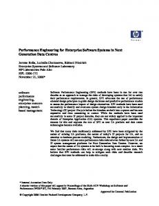
3.3 SE processes deployment resulting guide In addition to the deployment language and the stages presented above, the equipped methodological guide for the SE process deployment aims to include all elements illustrated in Fig. 1. This guide is currently under development.
7
Fig. 1. Main elements of the equipped methodological guide
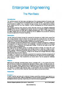
4 Application: ideal definition of the "Stakeholder requirements definition process" The purpose of this section is to show how to execute the first stage of the approach that is broken down into activities as shown in Fig. 2 and which has already been tested in industry. The process which is modelled is the "Stakeholder Requirements Definition" process described in [13]. It has been chosen since, according to SE principles, it is the first process that must be deployed. Moreover, [13] has been selected as SE referential since it is a generic standard widelyacknowledged in the SE community and in industry. Regarding now the modelling referential, we have selected the Business Process Modelling Notation (BPMN) [17] for the modelling language since
8
it is a widely-acknowledge standard. Nevertheless, it appears that BPMN suffers from semantic gaps when compared to other languages like the Event-driven Process Chains (EPC) from the ARIS method [18] which, for instance, clearly describes the notion of “Role”. This is due to its purpose: the first goal of BPMN is not to build conceptual model but to enable process model execution especially thanks to the Business Process Execution Language (BPEL)[16]. Thus, even if BPMN appears to be particularly interesting in our context, it requires enriching it conceptually with all necessary elements without introducing semantic or syntactic inconsistencies with the language original definition. For each SE process to deploy 1.1 Build the IDEAL model of the process to deploy +
1.2 Build the model of the IDEAL process managing the ideal process to deploy +
1.3 Build the model of the IDEAL deployment process for the ideal process to deploy and the process managing the ideal process to deploy +
Fig. 2. Break-down of the first stage of the approach
Activity 1.1 – Build the IDEAL model of the process to deploy Task 1.1.1 - Collect theoretical activities from the SE referential to have a first version of the process functional architecture The SE referential gives us a first version of the process break-down which can be graphically modelled as shown on Fig. 3. However, as the process graphical representation does not describe all attributes defined in the meta-model, they must be defined separately (to save space, they are not introduced here). Stakeholder Requirements Definition Process
+
Stakeholder Requirements Definition Process Elicit stakeholder requirements
+
Define stakeholder requirements
+
Analyze and maintain stakeholder requirements
+
Fig. 3. Illustration of Task 1.1.1
Task 1.1.2 - Identify the inputs and outputs of each activity This task consists in the identification of activities' inputs, which are roles that resources have to play, and outputs, which are flows or services. Unfortunately, BPMN does not provide notation for the
9
concept of “role” and its related relationships. Furthermore, the notions of pools and lanes do not totally meet the needs for resource’s description since it requires clearly associating resources to the roles they play. That is why an extension of BPMN is required and is currently under development. An example of this task is shown in Fig. 4 with the break-down of activity "Elicit stakeholder requirements". The concept of “role” is represented with ovals (with dotted line for company internal roles) and added relationships are explicitly named. Elicit stakeholder requirements Elicit stakeholders requirements
Identify stakeholders
+
+
needs
needs
Accountable for the activity
needs
needs
needs
List of stakeholders or List of stakeholders Accountable for the stakeholders classes activity requirements Responsible for the Responsible for the activity Stakeholder activity
Fig. 4. Illustration of Task 1.1.2
Task 1.1.3 - Identify who/what will perform the needed roles of identified activities If needed, roles are broken-down and classes of resources that can play the roles required by the activity are identified. If they must be played only by resources internal to the company, then "internal" roles are identified. Fig. 5 shows the example of the break-down and allocation of the "stakeholder" role. “Inherits from” and “plays” relationships have been added to this end, and classes of resources are symbolised with an icon of man. inherits from
Other interested parties
inherits from
Program manager
inherits from
Stakeholder inherits from
Customer
inherits from
inherits from
Final customer
Project_manager
State Representant plays
Private individual
Fig. 5. Illustration of Task 1.1.3 (simplified list of stakeholders)
All these tasks are then performed again but at a lower level of abstraction: the break-down of each activity is performed. During this
10
re-execution, if elements previously defined must be improved or completed, then they are. Activity 1.2. – Build the model of the IDEAL process managing the ideal process to deploy and Activity 1.3 – Build the model of the IDEAL deployment process for the ideal process to deploy and the process managing the ideal process to deploy These two activities perform again all tasks presented in Activity 1.1 respectively based on the generic processes proposed in Fig. 6 and Fig. 7 which must be instantiated according to the target SE process and the specificities of the company’s business area. Generic management process Manage the process execution
Manage the process monitoring
Manage the process communication
Manage the process improvement
Provide process definition and boundary
Organize the determination of improvement axis
Define and manage process documentation
Practically improve the process
Manage resources
+
Plan and define assessment
+
Perform the process assement
Manage decisions
+
+
Analyze results of assessment
+
Manage risks
+
+
+
+
+
Fig. 6. Management process Generic deployment process Manage the process training
Deploy tools
Manage the deployment communication
Manage Human Resources aspects
Plan the deployment
Develop communication kits Develop training material
+
+
Select tools
+
Organize the communication about the deployment
+
Train people
Install tools
+
+
Communicate
Officially define new affectations
Provide a schedule
+
+
Manage conflicts in the affectation
Organize deployment review
+
Fig. 7. Deployment process
+
+
11
4
Conclusion
This paper presents and illustrates a guide aiming to help companies in their deployment of SE processes. This guide's main strength is to map, mix and merge concepts taken from SE and EM domains. In addition to a deployment language and approach currently tested by a helicopter manufacturer; a set of support tools including software and methodological tools such as interoperability assessment methods or interview guides is being specified and developed.
Bibliography [1] GERAM: Generalised Enterprise Reference Architecture and Methodology - version 1.6.3, IFIP-IFAC Task Force, 1999. [2] ISO/DIS 11354-1 - Advanced automation technologies and their applications - Part 1: Framework for enterprise interoperability, ISO, 2010. [3] Systems engineering handbook - A guide for system life cycle processes and activities - v3.2, INCOSE, January 2010. [4] ATHENA project, Deliverable D.A1.4.1 -Framework for the establishment and management methodology, 2005. [5] ATHENA project, Deliverable D.A4.2 - Specification of interoperability framework and profiles, guidelines and best practices, 2007. [6] C4ISR, Final report, C4ISR Architecture Working Group, 1998. [7] V. Chapurlat and C. Braesch, Verification, validation, qualification and certification of enterprise models: Statements and opportunities, Computers in Industry 59 (2008), no. 7, 711 – 721, Enterprise Integration and Interoperability in Manufacturing Systems. [8] V. Chapurlat, B. Vallespir, and H. Pingaud, An approach for evaluating enterprise organizational interoperability based on enterprise model checking techniques, Proceedings of the 17th IFAC World Congress, 2008. [9] Nicolas Daclin, Contribution au développement d'une méthodologie pour l'interopérabilité des entreprises, Ph.D. thesis, Université Boredeaux 1, 2007. [10] DoD, DoD architecture framework - version 1.5, 2007. [11] Thomas Ford, John Colombi, Scott Graham, and David Jacques, The interoperability score, CSER - Conference on systems engineering research, 2007. [12] Wided Guédria, David Chen, and Yannick Naudet, A maturity model for enterprise interoperability, R. Meersman, P. Herrero, and T. Dillon (Eds.): OTM 2009 Workshops, 2009. [13] ISO/IEC, ISO/IEC 15288:2008 - systems engineering - system life cycle processes, 2008. [14] Leon A. Kappelman, Brindging the chasm, Architecture Governance 3(2) (2007), 28. [15] M.J. Leite, Interoperability assessment, (1998). [16] OASIS, Web services business process execution language version 2.0, 2007. [17] OMG, Business process model and notation version 2.0, 2011. [18] A.-W. Scheer, Architecture of integrated information systems, Springer, 1992.. [19] G.F. Simons, L.A. Kappelman, and J.A. Zachman, Enterprise architecture as language, Complex Systems Design & Management (2010). [20] The Open Group, TOGAF version 9, 2009.
12
Appendix: The proposed meta-model