vertical layered Space-Time architecture (V-BLAST) and the Space-Time ..... [1] V. Tarokh, N. Seshadri, and A. R. Calderbank, âSpace-time codes for high data ...
MULTILAYERED SPACE-TIME BLOCK CODES FOR OFDM SYSTEMS Ahmed S. Ibrahim, Mohamed M. Khairy, and A. F. Hussein Electronics & Communications Department, Faculty of Engineering, Cairo University, Giza, Egypt. explicit orthogonalization of the transmitted signals is imposed by the transmit structure at all. Instead, the propagation Multi-input Multi-output (MIMO) channel itself is exploited to achieve the required signal decorrelation. One way to perform detection for this system is by using linear nulling and symbol cancellation. In the linear nulling technique, each substream in turn is considered to be the desired signal and the remaining substre ams are considered as the interferers. Using symbol cancellation, interference from already-detected components of the transmitted vector is subtracted from the received signal vector. This will result in a modified received vector that effectively has fewer interferers. The Multilayered Space-Time architecture [5] is a combination of V-BLAST and STTC providing reliable and very high data rate communication over narrowband wireless channels. It partitions antennas at the transmitter into small groups, and uses individual space– time codes to transmit information from each group of antennas. At the receiver, each individual space–time code is decoded by a linear processing technique that suppresses signals transmitted by other groups of antennas by treating them as interference. In this paper, we propose a novel method for combining V-BLAST with STBC producing VBLASTSTBC. VBLAST-STBC achieves high bit rate and good performance with low decoding complexity. Its performance is close to that of the VBLAST-STTC scheme presented in [5] with a much lower decoding complexity. This scheme is better used in flat fading channels. For frequency selective channels, Orthogonal Frequency Division Multiplexing (OFDM) [6], is usually used. OFDM transforms the frequency selective fading channel into multiple flat fading subchannels. MIMOOFDM scheme employs multiple transmit and receive antennas in an OFDM communication system. MIMOOFDM was first presented in [7], which applied the STTC [1] in frequency selective fading channels through an OFDM scheme. A simple Space-Time block coded OFDM (STBC-OFDM) transmitter diversity technique for wireless communications over frequency selective fading channels was presented in [8]. STBC-OFDM applies the conventional Alamouti scheme [2] on OFDM blocks instead of individual symbols. In this paper, we also propose a VBLAST-STBCOFDM scheme to be used in frequency selective channels. This scheme offers high bit rates in addition to the diversity gain, the robustness against frequency selective channels, and low decoding complexity.
Abstract— In this paper, we propose a combination of the
vertical layered Space-Time architecture (V-BLAST) and the Space-Time Block Codes (STBC) producing VBLAST-STBC, which shows a performance advantage over V-BAST in flat fading channels. We also propose VBLAST-STBC with Orthogonal Frequency Division Multiplexing (OFDM) producing VBLAST-STBCOFDM, which shows a performance advantage over VBLAST-OFDM in frequency selective fading channels. These two schemes are intended to provide reliable as well as very high data rate communication over Rayleigh fading channels. The simulations show the advantages of the proposed schemes over the original V-BLAST and V-BLAST-OFDM schemes.
I. INTRODUCTION Recently, Space-Time coding has gained much interest due to its capability of achieving better performance using transmit diversity. Transmit diversity can achieve diversity gain by transmitting from multiple spatially separated antennas. A number of space-time coding techniques have been proposed for transmit diversity [1][3]. First, Tarokh et al., introduced Space-Time Trellis Codes (STTC) [1], which is a joint design of coding, modulation, transmit and receive diversity to provide high performance. When the number of transmit antennas is fixed, the decoding complexity of STTC increases exponentially with the transmission rate. For lower decoding complexity, Alamouti [2] discovered a remarkably simple scheme for transmission using 2 transmit antennas with N receive antennas achieving diversity order of 2N , and providing a reliable transmission over flat fading channels. Furthermore, Tarokh et al., generalized this new scheme to an arbitrary number of transmitter antennas M leading to the concept of Space–Time Block Codes (STBC) [3] and achieving diversity order of MN . While all the aforementioned kinds of Space-Time codes tend to achieving better performance without increasing the transmission rate, Foschini has proposed a Layered Space-Time architecture to achieve high bit rate. V-BLAST, (Vertical Bell Laboratories Layered SpaceTime) [4], is a wireless architecture capable of realizing very high bit rates using multiple transmit antennas. The user’s bit stream is mapped to a vector of independently modulated signal components that are simultaneously transmitted. An essential feature of V-BLAST is that no
1
S / P
ST Encoder
− X 2 * X1 X * X 1 2
Group 1 Tx Data DeMux
1
1
Prefix Removal & FFT
IFFT & Cyclic Prefix
2
2
Prefix Removal & FFT
IFFT & M-1 Cyclic Prefix
Group G S / P
IFFT & Cyclic Prefix
ST Encoder
− X M * X M −1 X M −1 * X M
IFFT & Cyclic Prefix
M
N-1
Prefix Removal & FFT
N
Prefix Removal & FFT
Interference Cancellation using Null Space Matrix
Symbols Dectection & Subtraction
Rx P Data / S
Subtract Detected Symbols
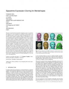
Figure 1. Block Diagram of VBLAST -STBC-OFDM
The outline of this paper is as follows. In Section II, we describe the system overview of the VBLAST-STBCOFDM including the frequency selective fading channel model. In Section III, we describe the mathematical analysis for the complete system. In Section IV, we show the simulation results for both flat and frequency selective fading channels. Finally, section V concludes the paper.
number of transmit antennas in each group is m g , g = 1,2, L, G , where m1 + m2 + L + mG = M . Each group is then encoded using a STBC-OFDM encoder [8]. We will consider that the number of transmit antennas in each group is two, so that m1 = m2 = L = mG = 2 . STBC-OFDM encoder formats each two OFDM blocks in Alamouti's orthogonal matrix form as − X i +1 * X i X i +1 Xi*
II. SYSTEM OVERVIEW
Where X i = ( x i (1) xi (2) L x i ( K ) ) is the OFDM
As for the channel model, we will consider the general case of frequency selective fading channels, and consider the flat fading channel as a special case. We assume that the MIMO frequency selective Rayleigh fading channel is invariant during each OFDM block, but is allowed to vary from block to block. Let α n = α n [ 0] α n [1] L α n [ L] be the i, j i, j i, j i, j baseband equivalent FIR channel between the ith transmit antenna and the jth receive antenna during the n th block,
block to be transmitted from antenna i . (*) represents the complex conjugate. Then the STBC-OFDM encoder performs the IFFT (Inverse Fast Fourier Transform) and adds a cyclic prefix that exceeds the channel order. Finally, the resulting complex symbols are modulated and fed to its respective transmitter. At the receiver, the cyclic prefix is first removed from each received vector, and then FFT is applied on each vector. To decode each group, the Null Space Matrix method presented in [5] is used to suppress the interference from the other groups. We use this method to cancel the interference on each subcarrier. For each group, we use the STBC-OFDM decoder [8] to decode the OFDM blocks of this group. Detected symbols are subtracted from the received vectors to reduce the effect of interference on the undetected groups.
1 £ i £ M , 1 £ j £ N , and L is the maximum channel order of all MN channels.α in, j [ l] 's are independent and identically distributed (i.i.d.), zero-mean, complex Gaussian with variance 1 /( 2L + 2) . n The frequency response of α i, j on the kth subcarrier
III. MATHEMATICAL ANALYSIS
L − j 2π k l / K is hin, j ( k ) = ∑ α in, j [l ] e , 1≤k ≤ K l =0 Let H n (k ) be the N ´ M matrix having h in, j ( k ) as its
Considering VBLAST-STBC-OFDM, let transmitted OFDM codeword be x1(1) x1 ( 2) K x1 ( K ) x2 ( 2) K x2 ( K ) x 2 (1) X = M M O M x (1) x ( 2) L x ( K) M M M = ( X (1) X ( 2) L X ( K ) )
(i,j) th entry. We will take the VBLAST-STBC-OFDM only into consideration; VBLAST-STBC is only a special case. A high-level block diagram of a VBLAST-STBC-OFDM system is shown in Figure 1. M is the number of transmit antennas, N is the number of receive antennas, and K is the numb er of OFDM subcarriers. The number of transmit antennas is divided into G groups, where the
the
(1)
2
(
)
Where X ( k ) = x1 ( k ) x2 ( k ) L x M (k ) and xi (k ) is the transmitted symbol from the transmit
Let
T
æ h1,1 ( k) h 2,1 (k ) çç H m1(k ) = çç h1,2 ( k) h2,2 ( k ) M çç M çè h1, N (k ) h2,N ( k ) We can write, æ ö H (k ) = çç H ( k ) M G ( k ) ÷÷÷ m1 ø èç m1
antenna i = 1,2 ,L , M , on subcarrier k = 1, 2, L , K . Also, let the channel matrix on certain subcarrier k = 1, 2, L , K be
H (k ) =
K
K K O L
hm1,1(k ) ÷ö hm1 ,2 (k) ÷÷÷ (9) M ÷÷ hm1 ,N (k )÷÷ø (10)
(k ) M ,1 K h ( k ) Multiplying N m1 ( k ) by (10), we get M ,2 æ ö O M N ( k ).H ( k ) = çç N ( k ).H ( k ) M N (k ). G ( k) ÷÷÷ m1 m1 m1 m1 ø èç m1 h (k ) h (k ) L h (k ) 1, N 2, N M,N æ = çç N ( k ).H ( k ) M 0 ) m1 è m1 (2) Let At the receiver, and after removing the cyclic prefix and X (k ) applying DFT on the received vectors, the received m1 matrix is X ( k ) = LLLL h (k ) 1,1 h (k ) 1,2 M
h (k ) 2,1 h (k ) 2,2 M
y1 (2) K y1 (1) y 2 (2) K y 2 (1) Y = M M O y (1) y (2) L N N = (Y (1) Y (2) L Y (K ))
h
Where X
(3)
N
)
zero-mean
Or in vector form, Y ( k ) = H ( k ). X (k ) + W (k )
Where
the
matrix
ö ÷÷ ÷÷ ÷÷ ø÷÷
and
X
(6)
m1
(k ).X
m1
m1
(k ) + N
m1
(k ).W( k)
(k ) +W% (k )
(14)
(k ).Y ( k ) , H% ( k) = N ( N − M + m1 ) ×1
(13)
m1
( k).H (k )
~ vectors, and H ( k ) is
n
X1 X2 = M X M −1 XM
,
X
n +1
− X2 * X1* = M − X M * X M −1 *
time slots. So, the received vectors at time slots n and n + 1 are
The null space matrix for Gm1 ( k ) is N m1( k ) where
x1 ( k ) ~ n ~ ~ + W ( k ) Y n ( k ) = H n ( k ). x 2 (k )
Nm1 ( k ) is ( N − M + m1 ) × N , such that (7)
~ Y
N m1 ( k ) by (5), we get
N m1 ( k ).Y (k ) = N m1 ( k ).H ( k).X (k ) +N m1 (k ).W (k )
m1
~ Assuming that H n ( k ) is constant for two consecutive
rank[ Gm1 ( k )] £ M - m1 .
Multiplying
( k).H
Now we have suppressed the interference from the other groups, and have reached a simple equation that relates the output to the input of the first group only. We will use STBC [2], [3] to decode the symbols of the first group. After decoding them, we subtract their effect from the received vectors which will be used for decoding the next group, and so on. For STBC, The transmitted OFDM symbols at time slots n and n + 1 are Where X 1 = ( x1 (1) x1 ( 2) L x1 ( K ) ) .
Gm1 ( k ) is N × ( M − m1 ) , and
N m1 (k ).Gm1 (k ) = 0
m1
( N − M + m1 ) × m1 matrix.
(5)
hM ,1 (k) hM ,2( k) M hM , N ( k)
( k).Y ( k) = N
~ ~ Y (k ) and W ( k ) are
To describe the group interference suppression method [5], let the desired group be the first group; with m1 transmit antennas, and all the other groups are interferers. Assuming that N ≥ M − m1 + 1 , let æ hm +1,1( k) hm +2,1(k ) K 1 çç 1 h ( k ) h ( k ) K ç m + 1,2 m + 2,2 1 Gm1 ( k) = ç 1 M M O çç L èçhm1+1,N (k ) hm1 +2,N (k)
m1
where Y%( k ) = N
y1 ( k) x1 (k ) w1 (k ) y2 (k ) x2 (k ) w 2 (k ) (4) = H ( k ). + M M M y (k ) x ( k) w ( k) N M N where w j (k ) 's, j = 1, 2, L , N , are independent complex
with
(k ) is m 1 ´1 , which is the symbols of the
Or in another form, Y%(k ) = H% ( k). X
j = 1, 2, L , N , on subcarrier k = 1, 2, L , K such that,
variable
m1
first group. So,
Where Y ( k) = y1 ( k) y2 ( k) L y N (k ) T and y j (k ) is the received symbol on receive antenna
Gaussian random variance N 0 .
(12)
X ( k) M − m1
y1 (K ) y 2 (K ) M y N (K )
(
(11)
n +1
~ (k ) = H
n
− x 2 (k ) * ~ + W ( k ). x1 (k ) *
n +1
(15) (k )
(16)
Using the linear processing [2] at the receiver, we can decode x1 ( k ) and x 2 (k ) , for k = 1, 2, L , K .
(8)
3
better than the original VBLAST-OFDM with M = N = 4 by more than 7 dB, better than that with M = N = 2 by 2 dB.
IV. SIMULATION RESULTS For the simulations of VBLAST-STBC and VBLASTSTBC-OFDM, we choose the number of transmit antennas and the number of receive antennas to be 4. Also, we have two groups with equal number of transmit antennas in each group. So, M = N = 4 and m1 = m2 = 2 . The modulation type is QPSK which gives a total bit rate of
4 ( xmtrs ) ´ 2 (bits / symbol / xmtr ) = 4 bps / Hz 2(time slots )
In order to evaluate these two schemes; First, we compare each one of them with the original VBLAST and VBLAST-OFDM, respectively, when the number of transmit antennas and receive antennas are fixed at 4, giving a total bit rate of 4 ( xmtrs ) x 2 (bits / symbol / xmtr ) = 8 bps / Hz
Figure 3. Frequency selective fading channel with QPSK modulation, K=256 subcarrier, and 2-ray Jakes model with delay spread = 5µs.
Second, we make the same comparison when the total rate is fixed at 4 bits, so the number of transmit and receive antennas, in case of the original VBLAST and VBLAST-OFDM, is only 2, M = N = 2 . Figure 2. shows the performance of VBLAST-STBC over flat Rayleigh fading channel. We observe that, at the Bit Error Rate of 10 −1 the VBLAST-STBC is better than the original VBLAST with M = N = 4 and M = N = 2 by 5 dB.
V. CONCLUSION We have proposed two schemes aiming at achieving high data rate with reliable transmission. VBLAST-STBC is used in flat fading channels, and VBLAST-STBCOFDM is used in frequency selective fading channels. Simulations showed a great improvement in the Bit Error Rate for the mentioned schemes over the original VBLAST architecture, either fixing the number of transmit and receive antennas or fixing the bit rate.
VI. REFERENCES [1] V. Tarokh, N. Seshadri, and A. R. Calderbank, “Space-time codes for high data rate wireless communications: Performance criteria and code construction,” IEEE Trans. Inform. Theory, vol. 44, pp. 744–765, Mar. 1998. [2] S. M. Alamouti, “A simple transmitter diversity scheme for wireless communications,” IEEE JSAC, vol. 16, no. 8, pp. 1451-1458, Oct. 1998. [3] V. Tarokh, H. Jafarkhani, and A. R. Calderbank, “Space-time block codes from orthogonal designs,” IEEE Trans. Inform. Theory, vol. 45, pp. 1456–1467, July 1999. [4] P. W. Wolnainsky, G. J. Foschini, G. D. Golden, and R. A. Valenzuela, “V-BLAST: An architecture for achieving very high data rates over the rich-scattering wireless channel,” in Proc. ISSSE-98, Pisa, Italy. [5] V. Tarokh, A. Naguib, N. Seshadri, and A. R. Calderbank, "Combined array processing and STC," IEEE Trans. Inform. Theory, vol. 45, no. 45, pp. 1121–1128, May 1999. [6] L. J. Cimini, Jr., "Analysis and simulation of a digital mobile channel using OFDM," IEEE Trans. Comm., vol. COM-33, no. 7, pp. 665–675,July 1985. [7] D. Agrawal, V. Tarokh, A. Naguib, and N. Seshadri, “Spacetime coded OFDM for high data-rate wireless communication over wideband channels,” in Proc. VTC, Ottawa, ON, Canada, May 18–21,, 1998, pp. 2232–2236. [8] K. F. Lee and D. B. Williams, “A space-time coded transm itter diversity technique for frequency selective fading channels,” in Proc. IEEE Sensor Array and Multichannel Signal Processing Workshop, Cambridge, MA, March 2000, pp. 149-152.
Figure 2. Flat fading channel with QPSK modulation.
Figure 3. shows the performance of VBLAST-STBCOFDM over frequency selective Rayleigh fading channel. In these simulations, we choose the same parameters as in [7]. Jakes model is used for correlated fading channels. We assume a 2-ray model with delay spread 5 µsec, and that the two paths undergo independent Rayleigh fading and are assumed to have equal average powers. The maximum Doppler frequency is 200 Hz. The available bandwidth is 1MHz and K = 256 carrier tones are used for OFDM modulation which corresponds to a subchannel separation of 3.9 KHz and block duration of 256 µsec. To each frame, a cyclic prefix of 5 µsec is added to combat the effect of Intersymbol interference. At the Bit Error Rate of 10 −2 , the VBLAST-STBC-OFDM is
4