Published on 15 January 2018. Downloaded by Beijing University of Chemical Technology on 14/05/2018 14:53:57.
Nanoscale View Article Online
PAPER
Cite this: Nanoscale, 2018, 10, 3245
View Journal | View Issue
Efficient perovskite/organic integrated solar cells with extended photoresponse to 930 nm and enhanced near-infrared external quantum efficiency of over 50%† Qiang Guo,a Hao Liu,a Zhenzhen Shi,a Fuzhi Wang,a Erjun Zhou, Bing Zhang,a Ahmed Alsaedi,c Tasawar Hayatc,d and Zhan’ao Tan
b
Xingming Bian,a *a
Enhancing the light-harvesting activity is an effective way to improve the power conversion efficiency of solar cells. Although rapid enhancement in the PCE up to a value of 22.1% has been achieved for perovskite solar cells, only part of the sunlight, i.e., with wavelengths below 800–850 nm is utilized due to the limited bandgap of the perovskite materials, resulting in most of the near infrared light being wasted. To broaden the photoresponse of perovskite solar cells, we demonstrate an efficient perovskite/organic integrated solar cell containing both CH3NH3PbI3 perovskite and PBDTTT-E-T:IEICO organic photoactive layers. By integrating a low band gap PBDTTT-E-T:IEICO active layer on a perovskite layer, the maximum wavelength for light harvesting of the ISC increased to 930 nm, sharply increasing the utilization of near infrared radiation. In addition, the external quantum efficiency of the integrated device exceeded 50% in the near infrared range. The MAPbI3/PBDTTT-E-T:IEICO ISCs show an enhanced short-circuit current Received 25th October 2017, Accepted 14th January 2018
density of over 24 mA cm−2, which is the highest existing value among perovskite/organic integrated solar
DOI: 10.1039/c7nr07933h
cells and much higher than the traditional MAPbI3 based perovskite solar cells. The results reveal that a perovskite/organic integrated structure is a promising strategy to extend and enhance sunlight utilization
rsc.li/nanoscale
for perovskite solar cells.
Introduction Due to the superior properties of a high optical absorption coefficient, high carrier mobility, long charge transport distance and suitable bandgap of perovskite materials,1,2 the power conversion efficiency (PCE) of an organic–inorganic hybrid perovskite solar cell (PSC) has exceeded 22% in the past several years.3 Perovskite is a type of material with an ABX3 crystal structure, such as calcium titanium oxide (CaTiO3); the organic–inorganic hybrid perovskite materials were first employed in a solar cell by the Miyasaka group.4 In 2012, Kim et al. employed ammonium lead iodide (CH3NH3PbI3) nanoparticles as light harvesters and creatively fabricated an alla
State Key Laboratory of Alternate Electrical Power System with Renewable Energy Sources, Beijing Key Laboratory of Novel Thin Film Solar Cells, North China Electric Power University, Beijing 102206, China. E-mail:
[email protected] b CAS Key Laboratory of Nanosystem and Hierarchical Fabrication, National Center for Nanoscience and Technology, Beijing 100190, China c NAAM Research Group, Faculty of Science, King Abdulaziz University, Jeddah 21589, Saudi Arabia d Department of Mathematics, Quiad-I-Azam University, Islamabad 44000, Pakistan † Electronic supplementary information (ESI) available. See DOI: 10.1039/ c7nr07933h
This journal is © The Royal Society of Chemistry 2018
solid-state PSC, which actually triggered perovskite photovoltaics.5 From then on, the methylamine (MA) lead iodine based perovskite, MAPbI3 with strong absorption in the range of 300–800 nm has been widely employed in PSCs.6,7 The bandgap of the organic–inorganic halide perovskite is tunable by changing the A, B or X site groups. For example, replacing I− by Br- on X site, higher open-circuit voltage (Voc) of the PSCs can be achieved. However, the MAPbBr3 based PSCs exhibit inferior photovoltaic performance compared with that of MAPbI3 based devices8–10 due to the wider bandgap and narrower absorption range of MAPbBr3. To broaden the optical absorption of MAPbI3, a formamidine ion (CH(NH2)2+) was chosen to substitute the methylamine ion (CH3NH3+) on the A site, so that the absorption edge of pure CH(NH2)2PbI3 can reach 850 nm.11–13 However, most of the NIR light could still not be effectively utilized. Recently, B site replacement was also conducted to obtain new perovskite materials. Typically, Tin (Sn) was used to replace or partially substitute Pb; the resultant Sn and Pb hybrid perovskite (CH3NH3Sn1−xPbxI3) exhibited a broad photoresponse up to 1060 nm.14–16 Unfortunately, the stability of Sn hybrid PSCs is not comparable to that of the Pb-based ones. Although the bandgap of the perovskite materials can be easily tuned by selecting the appro-
Nanoscale, 2018, 10, 3245–3253 | 3245
View Article Online
Published on 15 January 2018. Downloaded by Beijing University of Chemical Technology on 14/05/2018 14:53:57.
Paper
priate species of anions and cations at A, B, and X positions, the synthesis of stable low bandgap perovskite materials is still a challenge due to the limitation of the tolerance factor. To broaden spectra absorption and improve light harvesting of the photovoltaic devices, tandem structures with two or more spectrally complementary subcells have been designed. For an efficient tandem solar cell, the current generated in the front and rear subcells should be matched1 and the intermediate layer should be physically and electrically connected. Both the subcells should have a proper energy level alignment to reduce the resistance and anti-solvent property to protect the bottom subcell. Due to the complexity of the device structure, there are only a few successful demonstrations of perovskite/perovskite or perovskite/organic tandem solar cells.17–19 Compared to the series-connected tandem solar cell, perovskite/organic integrated solar cells (ISCs) exhibit numerous advantages. First, for organic semi-conductors, the bandgaps and energy levels of the molecules can be easily tuned by molecular tailoring; the low bandgap P-type and N-type organic materials with broad photo-absorption in the NIR range have been rapidly developed in the last few years.20–23 The short-circuit current density ( Jsc) of the low bandgap based OSCs has exceeded 22 mA cm−2 and the photo-response has achieved 1100 nm,24 which greatly facilitates the light-harvesting wavelength expansion for the perovskite/organic ISCs. Second, in ISCs the front and rear active layers are connected directly without an intermediate layer, which greatly simplifies the device fabrication. Third, the bulk-heterojunction (BHJ) OSC layer can be directly deposited onto the perovskite layer by spin-coating since the perovskite layer is resistant to the conventional solvent used for preparing the BHJ active layer. The first perovskite/BHJ ISC was proposed by Liu et al. in 2015.25 Subsequently, several studies have proven that integrating a suitable low bandgap BHJ active layer onto the perovskite layer can effectively broaden the spectral response of the PSCs, thus increasing the
Nanoscale
Jsc of the devices.26–29 However, the external quantum efficiency (EQE) of perovskite/BHJ ISCs is still low in the NIR range. Herein, we present an efficient perovskite/organic ISC and the BHJ organic solar cell, which consists of a low bandgap polymer PBDTTT-E-T donor and small molecule IEICO acceptor;22,30 their molecular structures are shown in Fig. 1. By depositing a PBDTTT-E-T:IEICO BHJ active layer on the perovskite layer, the photoresponse of MAPbI3/PBDTTT-E-T:IEICO ISC is pushed up to 930 nm, which is significantly wider than that of traditional MAPbI3 based PSCs (800 nm). The Jsc of ISCs is further improved as compared to the PSCs without a BHJ active layer. Furthermore, the ISCs based on MAPbI3/ PBDTTT-E-T:IEICO dual light absorption layer exhibit an EQE of more than 50% in the NIR range. The integrated current density ( Jint) of MAPbI3/PBDTTT-E-T:IEICO ISCs reaches 23.8 mA cm−2, which is much higher than that of MAPbI3 based PSCs (20.4 mA cm−2), which is the highest value among the reported perovskite/organic ISCs.
Experimental Materials Fluorine doped tin oxide (FTO) glass (15 Ω sq−1) was bought from Wuhan Geao (China). The chemicals 75% titanium (diisopropoxide) bis(2,4-pentanedionate) (TIPD) isopropanol solution, 1,8-diiodooctane (DIO), N,N-Dimethylformamide (DMF, 99.7+%) and Dimethyl sulfoxide (DMSO, 99.7+%) were purchased from Alfa Aesar. 4-Tertbutylpyridine (TBP) was bought from Sigma Aldrich. PbI2, CH3NH3I, and 2,2′,7,7′-tetrakis (N,N-di-p-methoxyphenylamine)-9,9-spirobifluorene (spiroOMeTAD) for perovskite films fabrication were purchased from Xi’an polymer Light Technology Co. Ltd. PBDTTT-E-T and IEICO were bought from Solarmer Co. Ltd. Precursor preparation Initially, 599.3 mg PbI2 and 101.6 mg DMSO were dissolved in 1 mL DMF and then stirred for 5 h. In addition, 50 mg mL−1 CH3NH3I was dissolved in isopropanol solution for the preparation of CH3NH3PbI3. Then, 10 mg mL−1 PBDTTT-E-T:IEICO was dissolved in chlorobenzene with a D : A mass ratio of 1 : 1.25 and the solution was stirred at 70 °C for 5 h. A volume ratio of 2% DIO was added into the PBDTTT-E-T:IEICO solution 30 min before the film deposition. Device fabrication
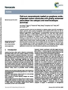
Fig. 1 (a) Device structure of MAPbI3/PBDTTT-E-T:IEICO ISC; (b) molecule structures of PBDTTT-E-T and IEICO; (c) energy level diagram of the MAPbI3/PBDTTT-E-T:IEICO ISC.
3246 | Nanoscale, 2018, 10, 3245–3253
The patterned FTO glass was washed twice in succession in detergent, water, deionized water, and isopropanol. The cleaned FTO was dried in nitrogen. Subsequently, 10 mL of TIPD/ethanol (1 : 9) solution was sprayed onto the FTO substrate using oxygen as a carrier gas and then sintered at 450 °C for 30 min to obtain a compact TiO2 (c-TiO2) layer. For OSC devices, 25 µL of PBDTTT-E-T:IEICO solution was deposited on c-TiO2 substrate by spin-coating at 1300 rpm for 60 s and then annealed at 100 °C for 10 min. The PBDTTT-E-T:IEICO layer
This journal is © The Royal Society of Chemistry 2018
View Article Online
Published on 15 January 2018. Downloaded by Beijing University of Chemical Technology on 14/05/2018 14:53:57.
Nanoscale
was prepared in a N2-filled glove-box. Following this, 10 nm MoO3 and 100 nm Ag were deposited by a thermal evaporator. For PSCs, about 200 nm mesoporous TiO2 (Dyesol, 30 nm particle paste) was coated onto c-TiO2 at 5000 rpm 30 s. Subsequently, the substrate was dried at 125 °C for 10 min and then sintered at 500 °C for 30 min. After the substrate cooled to room temperature, 30 μL of PbI2 precursor was spincoated on mp-TiO2 substrate at 3000 rpm for 30 s and then, 60 μL of CH3NH3I was spin-coated onto wet PbI2 at 3000 rpm for 30 s in a nitrogen filled glove-box. To form CH3NH3PbI3 film, the incompletely reacted film was taken out from the glove-box and annealed on a 100 °C hot platform for 30 min in ambient air with humidity of less than 30%. Then, 30 μL of spiro-MeOTAD solution (72.3 mg spiro-MeOTAD, 29 µL of 4-tert-butyl pyridine and 17.5 µL of lithium bis(trifluoromethanesulfonyl)imide (Li-TFSI) solution (520 mg mL−1 in acetonitrile) were dissolved in 1 mL of chlorobenzene) were spincoated on perovskite at 3000 rpm for 30 s. For the PSC using PBDTTT-E-T and IEICO as HTL, the PBDTTT-E-T and IEICO HTL were obtained by spin-coating 10 mg mL−1 PBDTTT-E-T chlorobenzene solution and 12.5 mg mL−1 IEICO chlorobenzene solution at 1300 rpm for 60 s, in sequence, and then annealed at 100 °C for 10 min. Finally, 100 nm Ag film was thermally evaporated under a pressure of 3 × 10⁻⁴ Pa. For the ISC devices preparation, the procedures for FTO/c-TiO2/ mp-TiO2/CH3NH3PbI3 films are the same as the single junction CH3NH3PbI3 devices. Following this, PBDTTT-E-T:IEICO was spin-coated onto the perovskite layer at 1300 rpm for 60 s and annealed at 100 °C for 10 min to obtain the CH3NH3PbI3/ PBDTTT-E-T:IEICO dual active layer. Finally, 10 nm MoO3 and 100 nm Ag were evaporated under atmospheric pressure (3 × 10⁻⁴ Pa). Instrumentations and characterizations The UV-Vis absorption spectra were measured using the Shimadzu UV-3600. AFM surface topography were investigated by an Agilent 5500 atomic force microscope (AFM) with tapping mode and SEM images were obtained by a HITACHI S4800 at acceleration voltages of 2.5 kV and 5 kV, respectively. PL was recorded using a FluoroLog-3 Modular Spectrofluorometer from HORIBA Scientific, and the samples for the PL test were excited by a 500 nm laser. TRPL was tested by Steady/Transient State Fluorescence Spectrometer F900 from Edinburgh Instruments. According to the PL test, the MAPbI3 samples for TRPL test were excited by 485 nm laser and the emission light was detected at 790 nm, while the PBDTTT-E-T:IEICO and MAPbI3/PBDTTT-E-T:IEICO films were excited by 485 nm laser and the emission fluorescence was detected at 900 nm. J–V curves were recorded using a computer controlled Keithley 2400 source meter under the lighting condition of a standard sunlight AM1.5G (100 mW cm−2). The light was provided by SAN-EI (AAA grade) solar simulator and calibrated with a standard Si solar cell. EQE was measured by QE-R systems (Enli Tech.). All the devices for J–V and EQE were unencapsulated and have an active area of 4 mm2 defined by perpendicular FTO and an Ag electrode.
This journal is © The Royal Society of Chemistry 2018
Paper
Results and discussion The perovskite/organic ISC with the structure of FTO/c-TiO2/ mp-TiO2/MAPbI3/PBDTTT-E-T:IEICO/MoO3/Ag is shown in Fig. 1a and the molecular structures of PBDTTT-E-T and IEICO are shown in Fig. 1b. In this multi-junction solar cell, the short-wavelength light is absorbed by the front perovskite layer and the long-wavelength light is utilized by the rear BHJ organic layer. The energy level diagrams of the ISCs are displayed in Fig. 1c; the highest occupied molecular orbital (HOMO) and the lowest unoccupied molecular orbital (LUMO) levels of each materials are acquired from the literature.22,31,32 For the MAPbI3/PBDTTT-E-T:IEICO ISC, when the light irradiates from the FTO side, the front MAPbI3 layer will first absorb the higher energy photons (1.53 eV) and then, free electrons and holes would be generated in the MAPbI3 layer. As the HOMO of PBDTTT-E-T (−5.09 eV) and IEICO (−5.29 eV) are slightly higher than that of MAPbI3 (−5.43 eV), the PBDTTT-ET:IEICO film can easily extract holes from the MAPbI3 layer and then transport them to the Ag electrode through a thin layer of MoO3 deposited on the PBDTTT-E-T:IEICO layer, which can block electron transport to the Ag electrode. Furthermore, the lower energy photons (1.34 eV) transmitted through the perovskite layer would be absorbed by the rear PBDTTT-E-T:IEICO layer to produce electron–hole pairs. As illustrated in Fig. 1c, a favorable energy offset is formed between the BHJ and perovskite layer since the LUMO levels of PBDTTT-E-T (−3.59 eV) and IEICO (−3.95 eV) are slightly higher than that of MAPbI3 (−3.9 eV). Therefore, the electrons generated in the BHJ active layer can be easily extracted by the MAPbI3 layer and finally be collected by the FTO electrode through the TiO2 electron transport layer. The UV-Vis absorption spectra of the MAPbI3, PBDTTT-E-T: IEICO and MAPbI3/PBDTTT-E-T:IEICO films are depicted in Fig. 2a. The absorption edges of the MAPbI3 and PBDTTT-E-T: IEICO films are 800 and 930 nm, respectively. When depositing PBDTTT-E-T:IEICO on MAPbI3 film to form a dual active layer, the absorption spectra is almost the sum of both the layers and the absorption edge also extends to 930 nm. This indicates that more NIR sunlight can be utilized in MAPbI3/ PBDTTT-E-T:IEICO ISC. Considering that the two adjacent perovskite and organic active layers are in direct contact in the ISC and both layers work as charge generation and transport layers, the charge mobility of perovskite and BHJ is critical for effective charge extraction and transport in both active layers to their corresponding electrodes. Since the perovskite materials manifest high charge mobility and long electron and hole diffuse length,33,34 the charge mobility of the PBDTTT-ET:IEICO film should have a great impact on the performance of the MAPbI3/PBDTTT-E-T:IEICO ISC. Therefore, the electron and hole mobility of the PBDTTT-E-T:IEICO film is tested using the space-charge-limited current (SCLC) method.35 Fig. 2b displays the current–voltage characteristic ( J–V) curves of single-electron (ITO/Al/PBDTTT-E-T:IEICO/Al) and singlehole (ITO/PEDOT:PSS/PBDTTT-E-T:IEICO/MoO3/Ag) devices. The electron and hole mobility of the PBDTTT-E-T:IEICO thin
Nanoscale, 2018, 10, 3245–3253 | 3247
View Article Online
Published on 15 January 2018. Downloaded by Beijing University of Chemical Technology on 14/05/2018 14:53:57.
Paper
Nanoscale
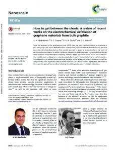
Fig. 3 (a, b) AFM topography (5 × 5 μm2) image and top view SEM image of MAPbI3, and (c, d) MAPbI3/PBDTTT-E-T:IEICO on FTO/c-TiO2/ mp-TiO2 substrate; (e) AFM topography (5 × 5 μm2) image of PBDTTT-ET:IEICO film on compact TiO2 substrate; (f ) cross section SEM image of FTO/c-TiO2/mp-TiO2/MAPbI3/PBDTTT-E-T:IEICO. Fig. 2 (a) UV-vis absorption spectra f PBDTTT-E-T:IEICO, MAPbI3 and MAPbI3/PBDTTT-E-T:IEICO films; (b) J–V curves of single-electron (ITO/Al(80 nm)/PBDTTT-E-T:IEICO/Al(80 nm)) and single-hole (ITO/ PEDOT:PSS(35 nm)/PBDTTT-E-T:IEICO/MoO3(10 nm)/Ag(80 nm)) devices.
film are calculated to be 2.71 × 10⁻³ and 4.24 × 10⁻² cm2 V−1 s−1, respectively. The hole mobility of the PBDTTT-E-T:IEICO film is comparable with PTAA (∼1 × 10⁻² to ∼1 × 10⁻³ cm2 V−1 s−1) and even higher than that of undoped spiro-MeTAD (∼1 × 10⁻⁴ cm2 V−1 s−1), which are widely used hole transport materials in PSCs.36,37 For photovoltaic devices, the surface morphology of each layer plays an important role in the performance of the device, particularly for multi-layered ISCs. To investigate the morphology of PBDTTTT-E-T:IEICO, MAPbI3 and the dual active layer in an ISC, atomic force microscopy (AFM) and scanning electron microscopy (SEM) measurements were conducted; the corresponding images are displayed in Fig. 3. Fig. 3a exhibits the AFM image of the MAPbI3 layer deposited on the FTO/ c-TiO2/mp-TiO2 substrate with a root-mean-square roughness (RMS) of 14.0 nm; the SEM image of MAPbI3 on an FTO/ c-TiO2/mp-TiO2 substrate is shown in Fig. 3b. It can be observed from the SEM image that the particle size of MAPbI3 is mostly in the range of 500 nm to 1 μm. In addition, there are no visible pinholes in MAPbI3 films as observed from the top view image and no voids between the perovskite grains as
3248 | Nanoscale, 2018, 10, 3245–3253
observed from the cross section SEM image (Fig. 3f ). The uniform, dense and large size crystal grain perovskite film is critical for efficient PSCs.38 In ISCs, a good crystallized perovskite substrate is also important for the formation of the PBDTTT-E-T:IEICO film. As shown in Fig. 3c, when the PBDTTT-E-T:IEICO layer was deposited on the MAPbI3, the RMS roughness decreased to 7.77 nm, which is much lower than that of the perovskite layer (14.0 nm); this is further confirmed by the SEM image as shown in Fig. 3d. For comparison, the AFM morphology of the PBDTTT-E-T:IEICO deposited directly on a FTO/c-TiO2 substrate without an MAPbI3 layer is also investigated, as shown in Fig. 3e, with a RMS roughness of 7.13 nm, which is very similar to that of PBDTTT-E-T:IEICO deposited on the MAPbI3 layer (7.77 nm). This indicates that the rougher surface of the MAPbI3 film has no significant effect on the rear BHJ organic film morphology, which is beneficial for the BHJ layer to obtain excellent performance. Fig. 3f displays the cross section SEM image of the perovskite/ organic ISC with a structure of FTO/c-TiO2/mp-TiO2/MAPbI3/ PBDTTT-E-T:IEICO. Each layer can be easily identified with sharp contrast with a thickness of about 200 nm for the c-TiO2/mp-TiO2 layer, 300 nm for the MAPbI3 layer and 130 nm for the PBDTTT-E-T:IEICO layer. To monitor the charge transport between the MAPbI3 and PBDTTT-E-T:IEICO layers, steady-state and time-resolved (TR) photoluminescence (PL) characterizations were investigated.
This journal is © The Royal Society of Chemistry 2018
View Article Online
Published on 15 January 2018. Downloaded by Beijing University of Chemical Technology on 14/05/2018 14:53:57.
Nanoscale
Paper
As illustrated in Fig. 4a, the MAPbI3 emits strong fluorescence with an emission peak at 790 nm. After depositing spiroOMeTAD as the hole-transport layer on an MAPbI3 layer, the fluorescence emission from perovskite significantly quenched, indicating that the charge in perovskite is effectively extracted by spiro-OMeTAD. Interestingly, when the organic BHJ layer PBDTTT-E-T:IEICO was deposited on the MAPbI3 layer, almost no fluorescence emission of MAPbI3 at 790 nm can be observed when excited with a 500 nm laser, indicating effective charge transfer between the perovskite and BHJ layers. In contrast, strong fluorescence emission belonging to the PBDTTT-E-T:IEICO can be detected in the range of 900–960 nm, which is much stronger than that of PBDTTT-ET:IEICO deposited on a quartz slide. The enhanced PL emission can be attributed to two main reasons. First, MAPbI3 can be excited to produce free holes and electrons and most of holes are transported to the PBDTTT-E-T:IEICO film. The holes from MAPbI3 can be recombined in the PBDTTT-E-T: IEICO film, resulting in enhanced fluorescence emission. Second, the emitted fluorescence from MAPbI3 (790 nm) can be absorbed by the PBDTTT-E-T:IEICO, so that PBDTTT-E-T: IEICO is excited by both the 500 nm laser and the fluorescence emission of MAPbI3. Thus, the hole–electron pairs generated
by the excitation in the PBDTTT-E-T:IEICO film are also increased, which leads to the increased recombination radiation and enhanced fluorescence emission of the PBDTTT-E-T: IEICO. To further verify the PL results, the time-resolved photoluminescence (TRPL) characterization of MAPbI3, PBDTTT-E-T:IEICO and MAPbI3/PBDTTT-E-T:IEICO films are also investigated as shown in Fig. 4b. The TRPL data are fitted by bi-exponential functions and the detailed fitting parameters are listed in Table S1.† 39,40 The average fluorescence lifetime of MAPbI3 is 36.02 ns. Compared with the pristine MAPbI3, the fluorescence lifetime of MAPbI3/PBDTTT-E-T:IEICO sharply decreased to 0.70 ns. However, the fluorescence lifetime of the MAPbI3/PBDTTT-E-T:IEICO dual active layer is still slightly longer than the PBDTTT-E-T:IEICO layer (0.68 ns), which is consistent with the PL test results. To utilize the complementary absorption of both the perovskite layer and the BHJ organic layer, perovskite/organic ISCs with a structure of FTO/c-TiO2/mp-TiO2/MAPbI3/ PBDTTT-E-T:IEICO/MoO3/Ag are designed and fabricated as shown in Fig. 1a. For comparison, control BHJ OSCs with a structure of FTO/c-TiO2/PBDTTT-E-T:IEICO/MoO3/Ag and control PSCs with a structure of FTO/c-TiO2/mp-TiO2/MAPbI3/ spiro-OMeTAD/Ag were also fabricated. The J–V curves of the corresponding devices are shown in Fig. 5a and device parameters are listed in Table 1. The control PBDTTT-E-T:IEICO
Fig. 4 (a) Steady-state PL spectra of PBDTTT-E-T:IEICO, MAPbI3, MAPbI3/spiro-OMeTAD and MAPbI3/PBDTTT-E-T:IEICO films deposited on quartz slides; (b) TRPL spectra of PBDTTT-E-T:IEICO, MAPbI3 and MAPbI3/PBDTTT-E-T:IEICO deposited on quartz slides.
Fig. 5 (a) J–V curves, (b) EQE and Jint curves of FTO/c-TiO2/ PBDTTT-E-T:IEICO/MoO3/Ag, FTO/c-TiO2/mp-TiO2/MAPbI3/spiroOMeTAD/Ag and FTO/c-TiO2/mp-TiO2/MAPbI3/PBDTTT-E-T/MoO3/Ag device.
This journal is © The Royal Society of Chemistry 2018
Nanoscale, 2018, 10, 3245–3253 | 3249
View Article Online
Paper Table 1
Nanoscale Photovoltaic performance parameters of OSC, PSC and ISC devices
Published on 15 January 2018. Downloaded by Beijing University of Chemical Technology on 14/05/2018 14:53:57.
PBDTTT-E-T:IEICO CH3NH3PbI3/spiro-OMeTAD CH3NH3PbI3/PBDTTT-E-T:IEICO
Scan
Jsc (mA cm−2)
Voc (V)
FF (%)
PCE (%)
Forward Reverse Forward Reverse Forward
14.94 21.61 21.81 24.07 24.48
0.819 1.122 1.096 0.993 0.935
58.52 74.49 70.68 60.97 54.36
7.17 18.06 16.89 14.57 12.44
OSC gives a PCE of 7.17% with a Voc of 0.819 V, a Jsc of 14.94 mA cm−2, and an FF of 58.52%. The control PSC demonstrates superior performance with reverse scan from 1.5 V to −1.5 V; the Voc, Jsc, FF and PCE are 1.122 V, 21.61 mA cm−2, 74.49% and 18.06%, respectively. For the perovskite/organic ISC, the four parameters of Voc, Jsc, FF and PCE with reverse scan are 0.993 V, 24.07 mA cm−2, 60.97% and 14.57%, respectively. Compared to the control PSC and OSC, the ISC shows severe hysteresis when the sweep direction is set as forward scan from −1.5 V to 1.5 V, The PCE of the control PSC still reaches 16.89%, while that of the ISC is only 12.44%. In general, the J–V curve hysteresis is commonly observed in PSCs due to charge recombination and ion migration.41,42 In our case, considering that the PSC and ISC have the same compact and mesoporous TiO2 layer, the severe hysteresis of ISC should be ascribed to the severe charge recombination within the BHJ organic layer since the transported holes from MAPbI3 could be aggregated in the HOMO of IEICO due to its limited hole mobility. However, compared with both PSC (21.61 mA cm−2) and OSC (14.94 mA cm−2), the Jsc of the MAPbI3/PBDTTT-E-T: IEICO ISC is greatly increased to 24.07 mA cm−2 (reverse scan). Fig. 5b illustrates the corresponding EQE curves of the PSC, OSC and perovskite/organic ISC devices. The single junction MAPbI3 device shows a broad plateau EQE in the range of 350–750 nm and then a cutoff at 800 nm; this data is consistent with that of the absorption spectra of the MAPbI3 film as shown in Fig. 2(a). The integrated current density ( Jint) from the EQE curve for MAPbI3 PSC reaches 20.4 mA cm−2, which is in good agreement with the value (21.61 mA cm−2) derived from the J–V curves. The OSC device displays a broad spectra response from 300 nm to 930 nm with a valley at the lower wavelength, giving a Jint of 14.3 mA cm−2 since the PBDTTT-E-T:IEICO film shows a strong absorption range from 600–700 nm and 750–800 nm, but weak absorption in the short-wavelength region (Fig. 2a).22,30 Moreover, the EQE of OSC devices can still reach 50% in the region beyond 800 nm, indicating that the PBDTTT-E-T: IEICO can provide a high current output in the range beyond the absorption edge of MAPbI3. Indeed, as compared to the single junction MAPbI3 PSC, the Jsc of the MAPbI3/ PBDTTT-E-T:IEICO ISC increases from 21.61 mA cm−2 to 24.07 mA cm−2 as shown in Fig. 5. The Jint of ISC reaches 23.8 mA cm−2 and the EQE is over 50% in the 800–830 nm, which is close to that of the single junction OSC device. To further validate that the BHJ layer does play an important
3250 | Nanoscale, 2018, 10, 3245–3253
role to boost the EQE of the ISCs, we fabricated the devices with the structure of FTO/TiO2/MAPbI3/IEICO/MoO3/Ag and FTO/TiO2/MAPbI3/PBDTTT-E-T/MoO3/Ag. The J–V and EQE performance of the devices using only PBDTTT-E-T or IEICO as HTL are shown in Fig. S1† and their detailed photovoltaic parameters are listed in Table S2.† The PBDTTT-E-T and IEICO HTL based devices show a PCE of 10.46% and 8.85%, respectively, indicating that both PBDTTT-E-T and IEICO can play the role of a hole-transporter in the BHJ layer, but the PBDTTT-E-T functions much better than the IEICO. The enhanced EQE of MAPbI3/BHJ ISC in the NIR region corresponds to the absorption of IEICO, while the EQE of the device based on only IEICO HTL is lower than 5% in the 800–900 nm range, which is much lower than that of the MAPbI3/BHJ ISC. It can be interpreted that the IEICO absorbs NIR light to produce excitons, while the excitons are separated into electrons and holes primarily at the interfaces between the PBDTTT-E-T and the IEICO in the BHJ layer. Then, the holes generated in the BHJ layer transport along PBDTTT-E-T to MoO3 and the electrons transport along IEICO to MAPbI3. Despite the ability of IEICO HTL to absorb NIR light, few excitons can separate into electrons and holes without the PBDTTT-E-T, so the IEICO HTL based devices cannot obtain a high EQE in the NIR region. In order to further increase the NIR light utilization for ISC, we fine-tuned the thickness and donor and acceptor mass ratio (D : A) of the PBDTTT-E-T:IEICO active layer in the ISC. The EQE performance of ISCs with different thicknesses of the BHJ layer are presented in Fig. S2† and the best EQE is obtained when the BHJ layer is about 130 nm. Compared with the devices with a 130 nm BHJ layer, the ISC with a 100 nm BHJ layer shows a lower EQE in the NIR region and can contribute to weaker absorption in the thinner BHJ layer. However, as the thickness of the BHJ layer increases to 160 nm, the EQE of ISCs in the NIR region drops from over 50% to about 45%, which may suffer from the increased charge recombination in the thicker BHJ layer. Clearly, increasing the ratio of IECO in the BHJ layer can enhance the absorption of NIR light. As the optimized D : A of PBDTTT-E-T and IEICO in OSC is 1 : 1.25, we tried to tune their D : A range from 1 : 0.8 to 1 : 2 in the ISC. However, when the D : A of PBDTTT-ET and IEICO is increased to 1 : 1.5 and 1 : 2, the EQE test of those ISCs are not showing superiority to that of the ISCs with D : A = 1 : 1.25 as shown in Fig. S3.† This result can be explained by the fact that IEICO has strong absorption in the NIR region and an appropriate thickness and D : A mass ratio
This journal is © The Royal Society of Chemistry 2018
View Article Online
Published on 15 January 2018. Downloaded by Beijing University of Chemical Technology on 14/05/2018 14:53:57.
Nanoscale
of PBDTTT-E-T:IEICO are helpful to achieve high efficiency of the ISC. It is noted that the J–V curves of ISC appear S shaped and the photocurrent of the ISC continues to increase even on decreasing the applied voltage (Fig. 5a). These anomalous phenomena indicate that the carrier transportation is hindered in the BHJ layer. To verify whether there is an impediment of hole transfer from PBDTTT-E-T to MoO3, we fabricated the device without the MoO3 layer (FTO/TiO2/MAPbI3/ PBDTTT-E-T:IEICO/Ag) to probe the carrier transportation and the S shaped J–V curves’ origin. However, as shown in Fig. S4,† the ISC without an MoO3 layer shows worse J–V curves and a lower EQE response. Moreover, the anomalous S shape does not disappear in the J–V curve, which indicates that the energy alignment between the PBDTTT-E-T and MoO3 does not cause the carrier to be hindered in the PBDTTT-E-T region. Moreover, from the J–V curve of the IEICO only based device, as shown in Fig. S1a,† we can observe the similar sign that the photocurrent continues to increase at a bias of −0.2 V and an S shape appears at the bias around 0.7 V, which indicates that the charge may be hindered in the IEICO region in the ISC. Though high hole-mobility of BHJ was obtained from the SCLC device and efficient charge transport between MAPbI3 and BHJ layer was verified by the PL test, when the ISC operated under light conditions, the carrier transportation in IEICO tended to be complicated. In the ISC, the IEICO simultaneously transported the hole from the MAPbI3 and generated electrons in the BHJ layer. It is inevitable that part of the holes and electrons are recombining in IEICO, which can be verified accurately by the enhanced PL emission of the IEICO in the MAPbI3/BHJ dual active layer (Fig. 4a). As explained earlier, a few of electrons were also generated in the IEICO HTL, which were much less than those in the BHJ layer, but the same recombination occurs in IEICO HTL. Hence, the same S shape is depicted in the J–V test of ISC and IEICO HTL based devices. We can conclude that the charge recombination in IEICO
Paper
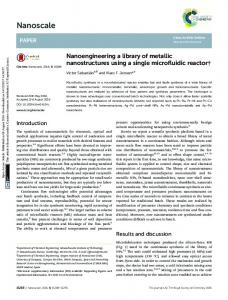
would lead to an obstacle in charge transport in the BHJ layer and cause the low fill factor of the ISC. Moreover, this obstacle and the charge recombination in the IEICO deteriorate the hysteresis of the ISC. The photovoltaic performance distribution of 20 individual MAPbI3 PSCs and MAPbI3/PBDTTT-E-T:IEICO ISCs was counted as depicted in Fig. 6. The Jsc for ISCs are clearly higher than that for single junction PSCs. The excellent current performance indicates that the front perovskite layer and rear BHJ layer can work together as active and charge transport layers and the PBDTTT-E-T:IEICO can provide additional current output compared to spiro-OMeTAD. However, it is disappointing that the Voc and fill factor (FF) of the ISCs are reduced, so the MAPbI3/PBDTTT-E-T:IEICO ISCs obtain a PCE of only 14.57% (reverse scan). The declined Voc can be ascribed to the mismatched energy level between the MAPbI3 and BHJ, which is less well-matched compared to MAPbI3 and spiro-OMeTAD. Because the deteriorated FF is caused by the charge recombination in IEICO, this problem may be solved by replacing the IEICO with an appropriate acceptor with both high hole and electron mobility to avoid charge recombination in the BHJ. It has been reported that a ternary blend based BHJ layer in ISC can improve the device FF.28 Nevertheless, more efforts are required to find a suitable third component for PBDTTT-E-T:IEICO BHJ and to validate the idea that a ternary blend based PBDTTT-E-T:IEICO BHJ can improve the FF effectively. Finally, to compare the influence of stability after introducing PBDTTT-E-T:IEICO BHJ OSC, we tested the stability of PSCs and ISCs in terms of the change in key parameters (Voc, Jsc, FF and PCE) with time. The unencapsulated PSC and ISC were tested in parallel both in a nitrogen filled glove-box and in the ambient environment (relative humidity of about 30%). The PCEs of PSC and ISC are normalized by their respective initial PCE (PCE0). As displayed in Fig. S5,† with a BHJ layer, the stability of the ISC is greatly improved both in the nitrogen filled glove-box and in the ambient environment. The PCE of PSC decayed to 88.0% and 69.5% of its initial PCE after aging in the glove-box and ambient environment for 240 h, while that of the ISC still remained at 91.0% and 74.3% of its initial PCE under the same conditions. The enhanced stability of the ISC should be ascribed to additional protection from the upper BHJ and MoO3 layers, which prevents the water infiltrating to MAPbI3.
Conclusion
Fig. 6 (a) Jsc, (b) Voc, (c) FF and (d) PCE distribution of 20 individual PSC (FTO/c-TiO2/mp-TiO2/MAPbI3/spiro-OMeTAD/Ag) and ISC (FTO/c-TiO2/ mp-TiO2/MAPbI3/PBDTTT-E-T:IEICO/MoO3/Ag) devices with reverse scan.
This journal is © The Royal Society of Chemistry 2018
In conclusion, we successfully demonstrated the wide spectral harvesting of MAPbI3/PBDTTT-E-T:IEICO ISCs. In these ISCs, both the MAPbI3 and PBDTTT-E-T:IEICO layers can absorb photons and produce charges. Moreover, the generated charges can transport between the two active layers, which is verified by the PL and TRPL tests. Benefitting from the current contribution of the low bandgap PBDTTT-E-T:IEICO active layer, the photoresponse of MAPbI3/PBDTTT-E-T:IEICO based
Nanoscale, 2018, 10, 3245–3253 | 3251
View Article Online
Published on 15 January 2018. Downloaded by Beijing University of Chemical Technology on 14/05/2018 14:53:57.
Paper
ISCs is pushed to 930 nm and their Jsc is enhanced to over 24 mA cm−2. Moreover, the EQE of the ISC is over 50% in the NIR region from 800 to 830 nm. Both the EQE and Jint are the highest values among perovskite/organic ISCs and much higher than that of MAPbI3 based PSCs. Although the PCE of the MAPbI3/PBDTTT-E-T:IEICO ISC is 14.57%, which is lower than the spiro-OMeTAD based PSCs, it will be greatly improved if the device voltage and fill factor deterioration problems of the ISC are solved. In particular, ISC is a novel and easy tool to extend the optical absorption and enhance the NIR light utilization of PSCs.
Conflicts of interest There are no conflicts to declare.
Acknowledgements This study was supported by the NSFC (51573042), the National Key Basic Research Program of China (973 Project, Grant 2015CB932201), the National Natural Science Foundation of Beijing (Grant 2162045), and Fundamental Research Funds for the Central Universities, China (JB2015RCJ02, 2016YQ06, 2016MS50, 2016XS47, 2016XS49, and 2017XS084).
References 1 H. J. Snaith, J. Phys. Chem. Lett., 2013, 4, 3623–3630. 2 F. Z. Wang, Z. A. Tan, S. Y. Dai and Y. F. Li, Acta Phys. Sin., 2015, 64, 038401. 3 W. S. Yang, B. W. Park, E. H. Jung, N. J. Jeon, Y. C. Kim, D. U. Lee, S. S. Shin, J. Seo, E. K. Kim, J. H. Noh and S. I. Seok, Science, 2017, 356, 1376–1379. 4 A. Kojima, K. Teshima, Y. Shirai and T. Miyasaka, J. Am. Chem. Soc., 2009, 131, 6050–6051. 5 H. S. Kim, C. R. Lee, J. H. Im, K. B. Lee, T. Moehl, A. Marchioro, S. J. Moon, R. Humphry-Baker, J. H. Yum, J. E. Moser, M. Grätzel and N. G. Park, Sci. Rep., 2012, 2, 591. 6 Q. Guo, C. Li, W. Qiao, S. Ma, F. Wang, B. Zhang, L. Hu, S. Dai and Z. A. Tan, Energy Environ. Sci., 2016, 9, 1486– 1494. 7 D. Y. Son, J. W. Lee, Y. J. Choi, I. H. Jang, S. Lee, P. J. Yoo, H. Shin, N. Ahn, M. Choi, D. Kim and N. G. Park, Nat. Energy, 2016, 1, 16081. 8 R. Sheng, A. Ho-Baillie, S. Huang, S. Chen, X. Wen, X. Hao and M. A. Green, J. Phys. Chem. C, 2015, 119, 3545–3549. 9 C. G. Wu, C. H. Chiang and S. H. Chang, Nanoscale, 2016, 8, 4077–4085. 10 J. H. Heo, D. H. Song and S. H. Im, Adv. Mater., 2014, 26, 8179–8183. 11 T. M. Koh, K. Fu, Y. Fang, S. Chen, T. C. Sum, N. Mathews, S. G. Mhaisalkar, P. P. Boix and T. Baikie, J. Phys. Chem. C, 2014, 118, 16458–16462.
3252 | Nanoscale, 2018, 10, 3245–3253
Nanoscale
12 G. E. Eperon, S. D. Stranks, C. Menelaou, M. B. Johnston, L. M. Herz and H. J. Snaith, Energy Environ. Sci., 2014, 7, 982–988. 13 S. Pang, H. Hu, J. Zhang, S. Lv, Y. Yu, F. Wei, T. Qin, H. Xu, Z. Liu and G. Cui, Chem. Mater., 2014, 26, 1485–1491. 14 F. Hao, C. C. Stoumpos, R. P. Chang and M. G. Kanatzidis, J. Am. Chem. Soc., 2014, 136, 8094–8099. 15 N. K. Noel, S. D. Stranks, A. Abate, C. Wehrenfennig, S. Guarnera, A.-A. Haghighirad, A. Sadhanala, G. E. Eperon, S. K. Pathak and M. B. Johnston, Energy Environ. Sci., 2014, 7, 3061–3068. 16 D. Zhao, Y. Yu, C. Wang, W. Liao, N. Shrestha, C. R. Grice, A. J. Cimaroli, L. Guan, R. J. Ellingson, K. Zhu, X. Zhao, R. G. Xiong and Y. Yan, Nat. Energy, 2017, 2, 17018. 17 D. Forgács, L. Gil-Escrig, D. Pérez-Del-Rey, C. Momblona, J. Werner, B. Niesen, C. Ballif, M. Sessolo and H. J. Bolink, Adv. Energy Mater., 2017, 7, 1602121. 18 C. C. Chen, S. H. Bae, W. H. Chang, Z. Hong, G. Li, Q. Chen, H. Zhou and Y. Yang, Mater. Horiz., 2015, 2, 203–211. 19 Y. Liu, L. A. Renna, M. Bag, Z. A. Page, P. Kim, J. Choi, T. Emrick, D. Venkataraman and T. P. Russell, ACS Appl. Mater. Interfaces, 2016, 8, 7070–7076. 20 H. Yan, Z. Chen, Y. Zheng, C. Newman, J. R. Quinn, F. Dotz, M. Kastler and A. Facchetti, Nature, 2009, 457, 679– 686. 21 L. Dou, C. C. Chen, K. Yoshimura, K. Ohya, W. H. Chang, J. Gao, Y. Liu, E. Richard and Y. Yang, Macromolecules, 2013, 46, 3384–3390. 22 H. Yao, Y. Chen, Y. Qin, R. Yu, Y. Cui, B. Yang, S. Li, K. Zhang and J. Hou, Adv. Mater., 2016, 28, 8283–8287. 23 J. C. Bijleveld, A. P. Zoombelt, S. G. J. Mathijssen, M. M. Wienk, M. Turbiez, D. M. de Leeuw and R. A. J. Janssen, J. Am. Chem. Soc., 2009, 131, 16616–16617. 24 E. Zhou, J. Cong, K. Hashimoto and K. Tajima, Energy Environ. Sci., 2012, 5, 9756–9759. 25 Y. S. Liu, Z. R. Hong, Q. Chen, W. H. Chang, H. P. Zhou, T. B. Song, E. Young, Y. Yang, J. B. You, G. Li and Y. Yang, Nano Lett., 2015, 15, 662–668. 26 C. Zuo and L. Ding, J. Mater. Chem. A, 2015, 3, 9063–9066. 27 L. Ye, B. Fan, S. Zhang, S. Li, B. Yang, Y. Qin, H. Zhang and J. Hou, Sci. China Mater., 2015, 58, 953–960. 28 J. Kim, G. Kim, H. Back, J. Kong, I. W. Hwang, T. K. Kim, S. Kwon, J. H. Lee, J. Lee, K. Yu, C. L. Lee, H. Kang and K. Lee, Adv. Mater., 2016, 28, 3159–3165. 29 M. Cheng, C. Chen, K. Aitola, F. Zhang, Y. Hua, G. Boschloo, L. Kloo and L. Sun, Chem. Mater., 2016, 28, 8631–8639. 30 L. Huo, S. Zhang, X. Guo, F. Xu, Y. Li and J. Hou, Angew. Chem., 2011, 50, 9697–9702. 31 P. Gao, M. Gratzel and M. K. Nazeeruddin, Energy Environ. Sci., 2014, 7, 2448–2463. 32 S. Lee, T. E. Kang, D. Han, H. Kim, B. J. Kim, J. Lee and S. Yoo, Sol. Energy Mater. Sol. Cells, 2015, 137, 34–43. 33 G. Xing, N. Mathews, S. Sun, S. S. Lim, Y. M. Lam, M. Gratzel, S. Mhaisalkar and T. C. Sum, Science, 2013, 342, 344–347.
This journal is © The Royal Society of Chemistry 2018
View Article Online
Published on 15 January 2018. Downloaded by Beijing University of Chemical Technology on 14/05/2018 14:53:57.
Nanoscale
34 S. D. Stranks, G. E. Eperon, G. Grancini, C. Menelaou, M. J. P. Alcocer, T. Leijtens, L. M. Herz, A. Petrozza and H. J. Snaith, Science, 2013, 342, 341–344. 35 Q. Guo, Y. Xu, B. Xiao, B. Zhang, E. Zhou, F. Wang, Y. Bai, T. Hayat, A. Alsaedi and Z. Tan, ACS Appl. Mater. Interfaces, 2017, 9, 10983–10991. 36 J. H. Heo, S. H. Im, J. H. Noh, T. N. Mandal, C. S. Lim, J. A. Chang, Y. H. Lee, H.-J. Kim, A. Sarkar, M. K. Nazeeruddin, M. Grätzel and S. I. Seok, Nat. Photonics, 2013, 7, 486–491. 37 L. Schmidt-Mende and M. Grätzel, Thin Solid Films, 2006, 500, 296–301. 38 W. Nie, H. Tsai, R. Asadpour, J. C. Blancon, A. J. Neukirch, G. Gupta, J. J. Crochet, M. Chhowalla, S. Tretiak,
This journal is © The Royal Society of Chemistry 2018
Paper
39 40
41 42
M. A. Alam, H.-L. Wang and A. D. Mohite, Science, 2015, 347, 522–525. J. H. Heo, H. J. Han, D. Kim, T. K. Ahn and S. H. Im, Energy Environ. Sci., 2015, 8, 1602–1608. C. Li, Q. Guo, W. Qiao, Q. Chen, S. Ma, X. Pan, F. Wang, J. Yao, C. Zhang, M. Xiao, S. Dai and Z. A. Tan, Org. Electron., 2016, 33, 194–200. H. S. Kim and N. G. Park, J. Phys. Chem. Lett., 2014, 5, 2927–2934. H. J. Snaith, A. Abate, J. M. Ball, G. E. Eperon, T. Leijtens, N. K. Noel, S. D. Stranks, J. T. Wang, K. Wojciechowski and W. Zhang, J. Phys. Chem. Lett., 2014, 5, 1511–1515.
Nanoscale, 2018, 10, 3245–3253 | 3253