Nanoscale View Article Online
Published on 02 February 2015. Downloaded by The University of Manchester Library on 01/05/2015 22:04:08.
REVIEW
View Journal | View Issue
How to get between the sheets: a review of recent works on the electrochemical exfoliation of graphene materials from bulk graphite
Cite this: Nanoscale, 2015, 7, 6944
A. M. Abdelkader,*a A. J. Cooper,a R. A. W. Dryfe*b and I. A. Kinlocha Since the beginning of the ‘graphene era’ post-2004, there has been significant interest in developing a high purity, high yield, and scalable fabrication route toward graphene materials for both primary research purposes and industrial production. One suitable approach to graphene production lies in the realm of electrochemical exfoliation, in which a potential difference is applied between a graphite anode/cathode in the presence of an electrolyte-containing medium. Herein we review various works on the electroReceived 23rd November 2014, Accepted 28th January 2015
chemical fabrication of graphene materials specifically through the use of electrochemical intercalation and exfoliation of a graphite source electrode, focusing on the quality and purity of products formed. We
DOI: 10.1039/c4nr06942k
categorise the most significant works in terms of anodic and cathodic control, highlighting the merits of
www.rsc.org/nanoscale
the respective approaches, as well as indicating the challenges associated with both procedures.
Introduction Since its initial fabrication by micro-mechanical cleavage,1 graphene, a single-atom-thick sheet of hexagonally arrayed sp2bonded carbon atoms, has attracted significant interest and shown great promise towards potential applications in nanoscience and nanotechnology. Graphene exhibits an ambipolar electric field effect,2–4 ballistic conduction of charge carriers,4,5 as well as the quantum Hall effect at room
a School of Materials, University of Manchester, Oxford Road, M13 9PL, UK. E-mail:
[email protected] b School of Chemistry, University of Manchester, Oxford Road, M13 9PL, UK. E-mail:
[email protected]
temperature.6–10 Some other attractive characteristics of graphene include high visible light transparency,11 impressive elasticity and thermal conductivity,12 unusual magnetic properties, and charge transfer interactions with molecules.5,13–15 Many efforts have been made to develop low-cost and largescale procedures for high-quality and high-purity graphene production. In contrast to micro-mechanical exfoliation,1 epitaxial growth16 and chemical vapor deposition,17–19 the chemical (and electrochemical) reduction of graphite oxide (GO) is much more commonly attempted,20–27 not only because of the low cost and high yield of the fabrication route, but also because of the chemical versatility of GO for subsequent chemical functionalization. However, there are currently several processing limitations associated with all chemical and
Amr M. Abdelkader received his PhD in 2011 from the University of Cambridge. Amr has 7 years of experience in electrochemical synthesis of nanomaterials. Amr is currently a research fellow at the Faculty of Engineering and Physical Sciences, University of Manchester, where his research focuses on the electrochemical properties of graphene and other 2D materials. A. M. Abdelkader
6944 | Nanoscale, 2015, 7, 6944–6956
Adam J. Cooper obtained his PhD from The University of Manchester in 2014 before undertaking a postdoctoral appointment at the University of Manchester’s Dalton Nuclear Institute as a research associate.
A. J. Cooper
This journal is © The Royal Society of Chemistry 2015
View Article Online
Published on 02 February 2015. Downloaded by The University of Manchester Library on 01/05/2015 22:04:08.
Nanoscale
Review
mechanical-based routes to graphene materials: These often include time-consuming laborious procedures, high operating temperatures, and aggressive solvents/reagents; all of which contribute to relatively high costs associated with the industrial scale-up of the procedures. These unfavorable reaction conditions are required in order to overcome the cohesive vdW energy (5.9 kJ mol−1) of the neighboring graphene sheets, necessary for successful graphene exfoliation from graphite sources. In addition, graphene sheets produced via GOreduction methodologies typically display relatively high sheet resistances, ranging from ca. 1 to ca. 70 kΩ sq−1,28 which are attributed to appreciable degrees of flake damage caused by the oxidation and exfoliation processes. Electrochemical approaches to the preparation of graphene materials involve the use of a liquid solution (electrolyte), and an electrical current to encourage structural deformation of a graphite working electrode, either via cathodic reduction or anodic oxidation of the graphite source electrode. The working electrode is typically a graphite rod/film/highly orientated pyrolytic graphite (HOPG) sample and is either anodically or cathodically loaded, though the latter approach is significantly less common than the former. Electrochemical approaches show considerable advantages over non-electrochemical solutionphase processing methods, since they typically take place via a single step, are relatively simple to operate, and can be performed under ambient conditions; making them industrially attractive. Furthermore, electrochemical approaches can be performed on the order of minutes-hours, in contrast to chemical/ sonication routes which are typically run over periods of several days.29,30 In addition, electrochemical routes have produced milligram and gram scale quantities31,32 of few-layer graphene materials with varying degrees of quality and purity, depending on the severity of the conditions employed, for example the operating voltage of the exfoliation procedure. Although electrochemical approaches are relatively recent, they have attracted interest from both industrial and academic researchers. This article will review recent work, which has hitherto been reported on electrochemical production of graphene materials. Graphite, constructed of >106 graphene layers with an interlayer spacing of 0.354 nm, is naturally abundant and relatively
easy to obtain as a source material in graphene production routes. Graphite reacts with a range of chemical compounds to form both covalent and ionic graphite intercalated compound (GICs). In ionic GICs, intercalants may be categorized as electron acceptor or donor species. Examples of electron accepting intercalants are H2SO4, HNO3, FeCl3 and H3PO4, whereas, common donor intercalating species are K, Rb, Li etc. Electrochemical exfoliation approaches are often based on the formation of GICs, and the physical expansion of the electrode, which occurs as a result, is utilized to exfoliate the graphite into its constituent layers. Depending on the charge of the ions intercalated into graphite, there are two natural approaches toward electrochemical production of graphene. The first approach, which has hitherto dominated the literature regarding both chemical, and electrochemical solutionbased graphene production routes, is based on the intercalation of anions into graphite anodes, mostly in aqueous electrolytes. The alternative method employs the use of cathodic control. In order to avoid any induced surface oxidation or chemical functionalization, necessary for the production of pristine and high quality graphene materials, cationic intercalation is arguably a more desirable route. Despite this obvious advantage provided by cationic intercalation, a relatively small number of groups have reported the successful production of graphene through the employment of purely cathodic control. Anodic preparation of graphene Electrochemical methods have been used to prepare electron acceptor GICs since the first half of the twentieth century. The so-called “acid salts of graphite” have been prepared using a graphite rods as an anode and a Pt counter electrode in concentrated sulphuric, chloro- and fluoro-sulphonic, selenic, perchloric, and nitric acid.33,34 Interestingly, it has been reported that these ‘graphite salts’ form ‘worm-like’ structures of expanded graphite upon rapid heating at elevated temperatures. These “worms” are actually graphene flakes, weakly bound together at the edges of the sheets, resulting in a porous structure with specific surface area as high as 130 m2 g−1.35–37 In a mixture of formic and sulphuric acids, graphite
Robert A. W. Dryfe is a Professor of Physical Chemistry at the University of Manchester. His research interests span the electrochemical properties of the liquid–liquid interface, and fundamental and applied aspects of the electrochemistry of graphene and related materials.
R. A. W. Dryfe
This journal is © The Royal Society of Chemistry 2015
I. A. Kinloch
Ian A. Kinloch is a Professor of Materials Science at the School of Materials, University of Manchester. He holds an EPSRC “Challenging Engineering” Fellowship, having previously held a Royal Academy Engineering/ EPSRC Research Fellowship. He works on the production, processing and applications of predominantly carbonaceous materials with a focus on composite and energy applications.
Nanoscale, 2015, 7, 6944–6956 | 6945
View Article Online
Published on 02 February 2015. Downloaded by The University of Manchester Library on 01/05/2015 22:04:08.
Review
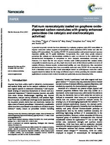
has been exfoliated to thin flakes consisting of 20 layers.38 With the emergence of the ‘graphene era’ and the subsequent need of a technology to produce large quantities of graphene suitable for industrial application, electrochemical exfoliation of graphite anodes was one of initial techniques suggested. Sulfonate salts have shown reasonable success on intercalation with graphite and subsequent exfoliation to graphene/ graphite nanoplatelet sheets. Wang et al.31 used 1 mM poly (sodium-4-styrenesulfonate) PSS solution and application of a 5 V constant voltage for 20 minutes. The produced powder was reported to contain some monolayer graphene flakes of about 1–2 μm lateral size. Li et al.39 employed sodium dodecyl benzene sulfonate (SDBS) solution as electrolyte and applied 30 V for 48 Hours. In this case, SDBS played a dual role, as both the intercalant and as a stabilizing surfactant for the graphene in solution. The resultant graphene sheets had a uniform thickness of ca. 1.2 nm after applying 30 V for 48 hours. The work was modified later using lower concentrations as well as application of only 25 V for 6 hours yielding similar results.40 Mensing et al.41 used 10 mg ml−1 solution of copper phthalocyanine tetrasulfonic acid to produce few-layer graphene materials. After application of 12 V between the graphite rod anode and graphite cathode, a black powder was obtained accompanied by a colour change of the electrolyte from blue to blue-green. The materials produced required sonication in an ultrasonic bath for an hour, post electrochemical exfoliation, in order to obtain graphene particles with 1 to 6 graphene-stacked layers. Lee et al.42 used 6-amino-4hydroxy-2-naphthalene-sulfonic acid mixed with NaOH as the electrolyte to exfoliate a graphite anode and an applied constant voltage of 20 V for 10–12 hours. The sulfonate anion again functioned as a surfactant for the graphene product in order to prevent the re-stacking of graphene flakes in aqueous media. Significantly, as is often the case with similar anodically controlled routes, FTIR and XPS analysis revealed the presence of oxidative functional groups bound to the surface of the product. Sulfate ions are an obvious choice based on their previous success in preparing GICs via electrochemical intercalation. In fact, electrochemical exfoliation of graphite anodes in sodium sulfate aqueous solutions has been previously reported to produce what have been referred to as ‘colloidal solutions’, since the mid-nineteenth century, which work in the 1990s showed was a GO solution.43 Approximately 20 years later, Zhu et al.44 successfully repeated the same experiment to prepare a graphene dispersion. Parvez et al.45 have tested different sulfate salts, including ammonium sulfate ((NH4)2SO4), sodium sulfate (Na2SO4), and potassium sulfate (K2SO4), claiming that the process is capable of producing flakes larger than 5 μm in lateral dimensions and ∼85% of flakes consisting of 1–3 layers (Fig. 1). The following mechanism was suggested: “(i) Applying bias voltage results in the reduction of water at the cathode, creating hydroxyl ions (OH−) that act as a strong nucleophile in the electrolyte. Subsequent nucleophilic attack of graphite by these OH− ions initially occurs at the edge sites and grain boundaries. (ii) Oxidation at the edge sites and grain boundaries subsequently leads to de-polarization and expan-
6946 | Nanoscale, 2015, 7, 6944–6956
Nanoscale
Fig. 1 The concept of the exfoliation through the intercalation of graphite with sulfate ions as explained by Parvez et al.45 Reprinted with permission from ref. 45. Copyright 2014, American Chemical Society.
sion of the graphite layers, thereby facilitating the intercalation of sulfate ions (SO42−) amid the graphitic layers. During this primary intercalation stage, water molecules may co-intercalate with the SO42− anions. (iii) Reduction of SO42− anions and self-oxidation of water produces gaseous species such as SO2 and O2. Zhang et al.46 used a Na2SO4-containing electrolyte and other metal sulfate salts to exfoliate graphite as well as in situ formation of Fe2O3-, Co3O4- and V2O5-graphene hybrids. Other graphene hybrids such as Mn2O3/graphene and LiMn2O3/graphene have been reported using similar methods.46 These graphene-hybrids have subsequently been implemented as both the anode and cathode in lithium ion batteries, exhibiting high specific capacities, stable cycling performances and excellent charge/discharge rate. It would appear that the pH of the solution effectively controls the kinetics of the intercalation and determines the type of the graphene product: In acidic media, the intercalation is so facile that many of the expanded graphite particles physically drop from the anode without complete exfoliation of the graphene sheets. Significantly, this is independent of the type of graphite employed as the anode material. This process results in relatively low yield of the graphene materials, and the produced graphene platelets are typically ‘thick’, consisting of many graphene layers, as well as closely resembling graphene oxide materials, in terms of surface oxidation, as opposed to pristine graphene. In a significant number of cases, the exfoliation products required additional sonication in order to produce reasonable amounts of graphene-like flakes.47,48 H2SO4 has become a popular choice of acidic media, and Liu et al.49 successfully exfoliated ‘pencil-graphite’ in H2SO4 using a multi-step potential program, and were able to isolate graphite oxide nanoplatelets within ca. 10 minutes. Parvez et al.50 reportedly used 1 M H2SO4 solution and applied a constant voltage of +10 V to a graphite rod anode. The process was extremely quick, with black powder precipitation resulting in solution after as little as two minutes of current application. The exfoliated powder was then collected via filtration and subjected to sonication in DMF for 10 minutes to
This journal is © The Royal Society of Chemistry 2015
View Article Online
Published on 02 February 2015. Downloaded by The University of Manchester Library on 01/05/2015 22:04:08.
Nanoscale
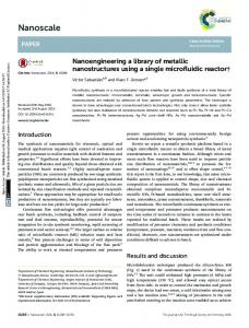
obtain graphene materials. However, there are several methods that have been suggested in the literature to avoid the fast intercalation of the sulfate ions and the subsequent formation of thick graphite flakes. Wu et al.51 began by expanding graphite at an applied bias of +1 V, initially for 10 min, followed by ramping the bias to +2 V for 20 min. Even with this modification, the resulting sample required further sonication in order to produce graphene with desired thickness: less than 4 layers thickness. Liu et al.52 further modified this electrochemical setup, implementing the graphite anode at the bottom of the cell, thus allowing any incomplete exfoliation to remain electrically contacted to the current collector, resulting in multiple intercalation/exfoliation steps and subsequent higher yield and thinner graphene materials (Fig. 2). Gee et al.53,54 added KOH to their solution in an attempt to control the oxidation at the anode and successfully produced solutions containing some monolayer graphene by this modification. Furthermore, stepwise application of the anode potential appears to generate a greater degree of control over the intercalation process, thus improving the degree of intercalation and producing ‘thinner’ graphene materials. Su et al.55 applied a potential of +1 V (vs. a Pt cathode) for ca. 5–10 minutes prior to application of +10 V bias. In this case, the exfoliated graphene sheets had thicknesses less than 3 nm and more than 65% of the sheets were thinner than 2 nm. Kuila et al.56 used an aqueous, sulfonated polyether ether ketone-(PEEK) polymer as the electrolyte. The exfoliation rate was significantly slower than the rate when employing H2SO4, and a stable dispersion of graphene was obtained in ca. 12 hours. However, it is not clear whether the mechanism involves the intercalation of sul-
Fig. 2 Schematic illustration of multiple electrochemical exfoliation (MEE) of spent graphite rod. Inset at the right is the digital photograph of the dispersed, exfoliated graphene sheets in DMF solutions, while corresponding, representative TEM images are shown in the middle inset. The mechanism of electrochemical exfoliation is depicted in eqn ((1)–(5)) consisting of anodic oxidation of water as well as intercalation of anions into graphite rod (Cs-surface of graphite rod, Cb-bulk of graphite rod). Schematic of graphite intercalation compound (GIC) with both hydroxyl and carboxyl groups formed by anodic insertion and anodic oxidization of water shows in middle part.52 Reprinted from ref. 52, copyright (2013), with permission from Elsevier.
This journal is © The Royal Society of Chemistry 2015
Review
fonated PEEK anions into the graphite anode, or PEEK adsorption on the surface of the graphite anode mediated by π–π interactions. The subsequent exfoliation mechanism could involve the formation of SO2 and/or CO2 gases between the graphene layers, forcing the layers apart, or detaching the surface graphene layer along with the adsorbed PEEK under constant electrical potential. The inclusion of dodecyl sulfate ions allows additional control advantages over other intercalating ions. Dodecyl sulfate compounds are well known surfactants for carbon nanoparticles, which thus prevent flake re-aggregation, a common problem in obtaining stable graphene solutions, via surface adsorption and electrostatic-stabilisation of neighbouring flakes in solution. Moradi et al.57 produced a stable suspension of graphene by applying +10 to +15 V constant voltage to a graphite anode in 0.1 M sodium dodecyl sulphate (SDS). Alanyalıoğlu et al.32 used 0.1 M SDS as electrolyte to produce graphene in a two-step process. In the first step, SDS intercalates into the graphite anode. The graphite intercalation complex (GIC) was then cathodically polarised to −1 V vs. Pt wire acting as a quasi-reference electrode, resulting in a stable colloidal graphene/SDS suspension. Liu et al.58 have also used an electrolyte containing 0.15 M Na2SO4 and 0.01 M SDS. The electrochemical cell was placed in a sonication bath and 6 V constant voltage applied. The graphite anode was completely consumed within an hour and it was claimed that bi-layer graphene flakes are dominant in the final product. Nitrate is also known to intercalate into graphite under polarisation conditions, which is partially attributed to its planar structure.59,60 At relatively high concentrations, nitric acid intercalates spontaneously via the formation of nitronium ions (NO2+), which in turn oxidize the graphite edges. Electrolytes that contains nitrate anions have been employed in the anodic exfoliation of graphene, both in pure ionic liquid based media and in aqueous electrolytes. In pure nitrate ionic liquids (ILs), no observable exfoliation was reported.61 However, the addition of water to the electrolyte in small proportions was found to facilitate the intercalation, generating reactive oxygen-containing species from water oxidation under the potentials applied, which in turn are able to sufficiently open the edges of graphene sheets and grain boundaries, thus resulting in the successful intercalation of nitrate and subsequent exfoliation of the graphite anode.61 The ability of the nitrate ions to dope graphene with nitrogen brings an additional advantage to the process, particularly for applications such as sensors and supercapacitors.61 Song et al.48 employed mild oxidative conditions to partially exfoliate graphite and decorate the resultant materials with polypyrrole for potential supercapacitor application. To achieve this controlled exfoliation, they used KNO3 solution in order to avoid high degrees of oxidation at the low pH. They also found that controlling the potential at 1.9 V (vs. saturated calomel electrode) is able to restrict the exfoliation to individual graphene sheets. As in the case of sulphate, the employment of nitrate ions and low pH appears to produce thicker graphite nano-platelets. It
Nanoscale, 2015, 7, 6944–6956 | 6947
View Article Online
Published on 02 February 2015. Downloaded by The University of Manchester Library on 01/05/2015 22:04:08.
Review
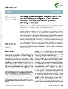
Fig. 3 Photograph showing changes in the solution colour during the electrolysis process.62 Reproduced from ref. 62 with permission from The Royal Society of Chemistry.
was found within our laboratories that the addition of nitrate to some organic ions hinders the rate of reaction at the anode; thus allowing more time for intercalation and oxidation processes to occur at the anode. This concept was used to prepare GO with an atomic oxygen ratio above 30% (Fig. 3).62 Chloride and perchlorate ions are also small enough to intercalate between the graphene sheets in graphite, but have so far not shown potential to exfoliate graphite in the absence of additional ionic species. However, they could be employed as a precursor, to promote the intercalation of larger molecules, in a similar manner to the aforementioned addition of water in order to facilitate nitrate intercalation, leading to flake exfoliation. Xia et al.63 demonstrated this by intercalating perchlorate ions first from sodium perchlorate solution in acetonitrile, before intercalating acetonitrile molecules into a graphite anode at a constant voltage of +5 V. The GIC was then subjected to a microwave irradiation step in order to induce graphene exfoliation. The process was reported to yield 50% of monolayer graphene. Phosphate ions have also been used to exfoliate graphite anodes. Zeng et al.64 cycled the potential of a graphite working electrode between 0 and +3 V vs. a saturated calomel electrode in phosphate buffer solution. The intercalation process resulted in the formation of oxygen functionalities (epoxy, hydroxyl carbonyl, and hydroxyl groups), which weaken the van der Waals attraction between the graphene sheets. It was found that the oxidation process produces gases (carbon dioxide and oxygen) between the graphene layers in the graphite gallery which aided the exfoliation. The product was pristine graphene oxide (GO) nanosheets with C/O atomic ratio of 3.45. Exfoliation using tetrafluoroborate anions has been investigated in aqueous electrolytes and in room temperature ILs, which allows the comparison between electrolytes with both narrow and large electrochemical windows, respectively. The product and the suggested mechanism of exfoliation are different in each case. When pure ionic liquid was used, the
6948 | Nanoscale, 2015, 7, 6944–6956
Nanoscale
product of the exfoliation process was described as a ‘bucky gel’, an extremely viscous medium that makes isolation of the graphene sheets challenging.65 Alternatively, the aqueous electrolyte decreases the viscosity of the solution, which facilitates the BF4− diffusion. As a result, the expanded volume of the graphite electrode was much greater for the aqueous electrolyte than for the pure ionic liquid. Lu et al.66 have suggested the following mechanism to explain the exfoliation process in BF4− aqueous electrolyte: (1) electrolysis of water at the electrode produces hydroxyl and oxygen radicals; (2) the oxygen radicals corrode the graphite anode at edge sites, grain boundaries and defect sites, which results in the opening up of edge sheets; (3) the room temperature IL anions intercalate via the edge sheets and initiate the electrode expansion; (4) the precipitation of some sheets results in the exfoliation of graphene sheets into solution. These procedures do not necessarily take place in a sequential order, but it is rather the interplay between the electrolysis of water and the intercalation of BF4− ions that is responsible for the production of the sheet exfoliation. Triethyl sulfonium bis(trifluoromethyl sulfonyl) imide is yet another ionic liquid that has been studied for electrochemical exfoliation. In this case, a pencil was employed as the working electrode, platinum (Pt) as a quasi-reference electrode, and Pt spiral as a counter electrode in a three-terminal cell.67 After application of +8 V, the pencil corroded and a black powder of graphite oxide was produced in solution. An extra sonication step was needed to convert this thick graphite oxide into few layer GO. Carboxylate ions have been successfully used to exfoliate graphite. Khanra et al.68 added both 9-anthracene carboxylate ion and sodium hydroxide to the electrolyte to produce graphene oxide nanoparticles. It has been suggested that the exfoliation mechanism is perhaps more complex than a simple intercalation of the carboxylate ions between the graphene sheets, and the subsequent exfoliation associated with gas formation. The authors suggested that the 9-anthracene carboxylate (ACA) ions were surface adsorbed on a positive electrode (anode) by electrostatic interaction. Subsequently, the graphite layers along with the ACA were separated from the anode under electrical potential and swollen in the aqueous solution. By repeating these processes, a layer-by-layer exfoliation of the graphite anode was achieved and some of the produced graphene oxide has a thickness less than 0.79 nm albeit with a high (22.48%) atomic oxygen content. There are several works that suggest using alkaline media to exfoliate graphite anodes, with the product being predominantly graphite oxide. Parker et al.69 applied +60 V between a graphite foil anode and a steel rod cathode in 1 M NaOH solution. Chang et al.70 used standard aqueous ammonium hydroxide solution and applied +10 V for ca. 30 minutes. The product in all cases was thick and functionalised by oxygencontaining groups that imparted aqueous solubility. Rao et al.71 studied the effect of adding H2O2 to NaOH solution to the electrochemical exfoliation process. The optimal exfoliation conditions were determined to be 3.0 M NaOH, 130 mM
This journal is © The Royal Society of Chemistry 2015
View Article Online
Published on 02 February 2015. Downloaded by The University of Manchester Library on 01/05/2015 22:04:08.
Nanoscale
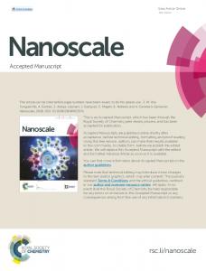
H2O2, and a working bias voltage of +1 V for 10 min and +3 V for 10 min at room temperature. The proposed mechanism and role of H2O2 was suggested: H2O2 reacts with OH− ions in the NaOH solution to form nucleophilic O22− ions. These nucleophilic ions intercalate graphite and the oxidized functional groups weaken the van der Waals forces between the graphene sheets, leading to successful exfoliation. The process involved in the majority of literature utilises chronoamperometry, in which a two-electrode system is used to apply a large potential difference, typically between +5 and +20 V, for times ranging between few minutes up to several hours. However, there were some attempts to use chronopotentiometric techniques in which the current is controlled and the potential is recorded as the dependent variable. Chronopotentiometry (CP) has many advantages that might favour it for electrochemical exfoliation processes. CP is simple, and needs less construction and operation considerations. Lee et al.72 applied a 300 mA constant current to a graphite foil anode in 1 mM poly(sodium-4-styrenesulfonate) PSS solution. The surface of the graphite foil was reported to exfoliate to graphene nanosheets with “wavy” structures, providing a high surface area. However, the exfoliation on the surface did not lead to separation of individual graphene flakes, which raises a question about the kinetics of PSS intercalation with graphite. The anion intercalation with graphite was not the only anodic process that has been used to produce graphene. Preparation of few layer graphene through anodic oxidation (“unzipping”) of multi-walled carbon nanotubes (MWCNTs) has also been reported.73 MWCNT working electrodes were kept at potential of 0.7 V for 6 h vs. mercury/mercury(I) sulfate (MMS) electrode in 0.5 M H2SO4 solution. The oxidation of MWCNTs initiates the breaking of sp2 carbon bonds at the tip of the MWCNTS and continues in a longitudinal direction, causing the tubes to break along a straight line. Similar oxidation processes have been used to unzip single wall carbon nanotubes producing ‘nanoribbons’. The oxidation processes generated significant amounts of oxygen-containing functional groups, resulting in a remarkable transformation into graphene oxide layers. It was therefore necessary to remove the oxygen functional groups in a second step in order to transform GO into something approaching graphene (Fig. 4). The chemistry of some of the reported exfoliation mechanisms can be unclear, not surprisingly due to the employment of extreme potentials, with authors offering different explanations for the resulting exfoliated nanomaterials. Some of the routes, especially when requiring the reduction of graphene oxide materials, employ complicated procedures, and concerns arise from the chemistry of these steps; harsh reagents and conditions with multiple steps make this an unfavorable practice, especially for industrial viability. In addition, additional sonication stages are undesirable from an industrial perspective, since the large scale implementation of sonication baths would prove costly, not to mention the relatively uncontrolled nature of the exfoliation process when driven via ultrasonic vibration.
This journal is © The Royal Society of Chemistry 2015
Review
Fig. 4 Typical AFM images of GNRs made from MWCNTs by the twostep electrochemical process. Top: Representative images of GNRs synthesized at (a) 0.7 and (b) 0.5 V. Bottom: TEM images of MWCNTs after two-step electrochemical treatment, revealing two to three layers of graphene sheets after (c) partial and (d) complete transformation of MWCNT.73 Reprinted with permission from ref. 73. Copyright 2011 American Chemical Society.
Cathodic production of graphene Though there have been significant efforts regarding anodically controlled graphene exfoliation procedures, including many works not mentioned in this review, all of the approaches share a common feature: they perform oxidation of the graphite anode source electrode through the use of oxidative potentials, and in all cases reported, generate materials that are at least partly oxidised, or functionalised by other species involved in the overall process. This is an unavoidable aspect of anodic intercalation, since the potentials required to facilitate ion intercalation are often greater than the potentials required to oxidize graphite. Although some authors have tried to address this, by involving some element of cathodic control throughout the procedure in an attempt to electrochemically reduce the surface-bound functionalities, most of these approaches actually depend on the formation of oxygen-containing functional groups to weaken the van der Waals forces between the graphene sheets, and permit exfoliation. These approaches are questionable when considering the electronic structure of pristine graphene; since oxygen-functionality causes significant disruption of the extended π-electron system and although it is subsequently reduced, it is generally accepted29,74 that all the modification processes result in irreversible changes to graphene’s electronic structure, thus preventing the restoration of the electronic qualities associated with pristine graphene.
Nanoscale, 2015, 7, 6944–6956 | 6949
View Article Online
Published on 02 February 2015. Downloaded by The University of Manchester Library on 01/05/2015 22:04:08.
Review
Although the issues associated with this oxygen functionality may not hinder the production of graphene for some potential industrial applications; which utilise graphene’s transparency and flexibility, some other applications may require pristine graphene particularly where electrical conductivity is of utmost concern. It is therefore essential for the exploration of non-oxidative routes toward production of graphene. For decades, graphite has been used as the negative electrode in lithium ion battery technology due to its high electrical conductivity and its ability to host lithium between the graphene layers. The lithium-graphite intercalation compounds decompose readily in water giving rise to lithium hydroxide and free standing graphene sheets. This principle was recently introduced as a route for scalable production of graphene.75 However, due to the slow kinetics of the intercalation process, the lithium was limited to the areas close to the edges. Upon exfoliation in water, graphite with expanded edges was produced and further intercalation, water decomposition and sonication steps were needed to achieve complete exfoliation (Fig. 5).76 Liu et al. and Huang et al.19,77 tried to accelerate the kinetics of the intercalation by using molten LiOH or LiCl at 600 °C, however the intercalation was still insufficient to achieve complete exfoliation of the graphite, and sonication steps were still required in order to achieve reasonable yields of graphene materials. Swager and Zhong78 propose a method to intercalate graphite initially with Li+ followed by tetraalkylammonium cations in two separate steps. However due to the expanding nature of the cathode, the initial distance between electrodes was large and thus a high potential difference was required in order to
Fig. 5 (a) TEM images and electron diffraction pattern for FLG. (b) Electron diffraction patterns of (i) single and (ii) bilayer sheets. (c) AFM image of FLG spin-coated onto a Si substrate. The thickness was ∼1.5 nm, corresponding to a bilayer. (d) (left) Raman spectra (532 nm laser) of FLG on Si substrates compared with the spectrum of graphite; (right) Lorentzian peak fitting of the 2D bands of the bilayer and trilayer.76 Reprinted with permission from ref. 76. Copyright 2011 American Chemical Society.
6950 | Nanoscale, 2015, 7, 6944–6956
Nanoscale
overcome the high Ohmic drop created by the electrolyte and this cell configuration. As a result, the organic solvent used as electrolyte dissociated in the latter stages of the procedure thus hindering the intercalation process. Therefore, an additional sonication step was again necessary to achieve reasonable exfoliation. Dimethylsulfoxide (DMSO) has a wide electrochemical window and it has been found to be a highly effective solvent towards graphene-solvent dispersion, showing typical dispersive qualities matching those of NMP.79 In addition, DMSO forms solvated ions with both lithium and alkylammonium ions. These solvated ions are able to intercalate with graphite and decompose between the graphene layer forming SO2 and/ or some amine-based gases. The stress applied on the graphene sheets by this gaseous expulsion is enough to overcome the van der Waals forces attracting neighboring sheets, permitting separation of the graphene sheets from the graphite cathode and allowing dispersal in the electrolyte solution. The authors of this work80 have used this principle to produce large flakes (up to 20 µm lateral dimension) of few-layer graphene using DMSO-based electrolyte containing triethylammonium and Li ions. They have since fashioned an electrochemical program applying a controlled cathodic potential to the graphite electrode, which allows complete intercalation before flakes spontaneously exfoliate from the cathode due to the partial expansion. It was suggested that the triethylammonium ions are dissociated between the layers to give triethylamine and hydrogen gases, which encourages exfoliation of the flakes. Zhou et al.81 have so far presented the only known method to exfoliate graphite cathodes in aqueous media., using an electrolyte containing NaCl, DMSO, and thionin acetate salt. After application of a 5 V constant voltage, sodium ions combine with four or five DMSO molecules to form Na+/DMSO complexes. These complexes intercalate into the graphene galleries of graphite to form ternary graphite intercalation compounds (Na+(DMSO)yCn−). The interlayer spacing of this compound was reported to be 1.246 nm. However, complete exfoliation could not be achieved through electrochemical treatment alone, and the sample was subjected to sonication in order to obtain stable graphene dispersions. The samples were heavily contaminated with sulfur, oxygen and nitrogen.81 Yang et al.82 employed a pure ionic liquid, N-butyl, methylpyrrolidinium bis(trifluoromethylsulfonyl)-imide (BMPTF2N) for the cathodic intercalation/exfoliation of graphite. According to the authors, [BMP]+ cations intercalate into the highly negative charged graphene layers causing the interlayer spacing to expand. This expansion facilitates the insertion of bigger molecules such as the BMPTF2N ion-pair, which subsequently leads to larger expansion in the graphite. The authors claimed to form graphene sheets consisting of between two and five layers, 2.5% atomic% oxygen and free of defects. However, the authors did not offer an explanation for the gel-like phase usually formed from the ionic liquid when the cations or anions are consumed in these irreversible reactions.61,65
This journal is © The Royal Society of Chemistry 2015
View Article Online
Published on 02 February 2015. Downloaded by The University of Manchester Library on 01/05/2015 22:04:08.
Nanoscale
Wang et al.76 demonstrated a purely cathodic technique in which lithium/propylene carbonate (PC) insertion is performed between the graphene layers. However, this process requires an additional sonication step to produce electrode exfoliation and the potentials required are in excess of −15 V. It is unclear whether the intercalation or the sonication stage is the primary reason for the observed exfoliation, although the authors explicitly state that lithium is necessary for successful exfoliation. They also propose another mechanism in which NaOH is intercalated and found to improve exfoliation efficiency up to 20 times. Cooper et al. have shown that tetraalkylammonium salts can be cathodically intercalated into HOPG using relatively small potentials (ca. −2 V),83 and can be employed to produce purely cathodically exfoliated materials consisting of between 2 and 5 layers (see Fig. 6).84 Perhaps more significantly, the materials were found to contain no functionality or oxidation other than slight 1% atomic% of oxygen, thought to be induced from atmospheric exposure of the isolated materials.
Fig. 6 (a) Photographs of as prepared HOPG, (b) HOPG expansion after 1000 s tetraethylammonium cation intercalation, (c) HOPG expansion after 1000 s tetrabutylammonium cation (TBA+) intercalation, (a–c scale in mm) (d) HOPG expansion after 10 000 s TBA+ intercalation, (e) SEM image of HOPG expansion after 6000 s TBA+ intercalation, (f ) SEM image showing micron sized pores in HOPG after TBA+ intercalation, (g) SEM image showing selective exfoliation of HOPG electrode: the point on a HOPG electrode that was held by tweezers (left hand side) whilst the rest of the electrode (right hand side) was submerged.84 Reproduced without changes from ref. 84. Copyright 2014, Elsevier Inc., reproduced under Creative Commons license CC-BY3.0.
This journal is © The Royal Society of Chemistry 2015
Review
Yang et al.82 also report on a cathodic intercalation route that does not rely on other processing methods, such as sonication or microwave expansion, using N-butyl, methylpyrrolidinium bis(trifluoromethylsulfonyl)imide IL. The potentials required were, however, on the order of −30 V. Electrochemical exfoliation of other 2D materials Graphite is not the only natural material that exists as a layered structure. Transition metal dichalcogenides (TMDs), transition metal oxides (TMOs), and other compounds such as BN, Bi2Te3, and Bi2Se3 also exist in nature and have layered structures. Also, synthetic binary carbides and nitrides are composed of layers which form 3D crystals when stacked along the c-axis. These layered materials represent a diverse and largely untapped source of two-dimensional (2D) systems with unusual electronic properties and high specific surface areas. In truth, isolation of a single layer of such layered compounds has been known for several decades prior to the discovery of graphene.85,86 The exotic chemical, physical and mechanical properties of these 2D systems make them strong candidates for many applications such as sensing, catalysis, and energy storage applications. Although exfoliation can be performed via small-scale mechanical cleavage,87,88 large-scale production methods are still desirable in order to fulfill the requirements associated with industrial scalability. As with graphene, various liquid phase exfoliation methods have been proposed. These methods, whether involving chemical reactions89,90 purely sonication,91 or ball milling92 with solvent involvement, are laborious and time-consuming, extremely damaging to the environment, and, as with graphene synthesis, often result in significant contamination of the products. TMDs are one of the more interesting materials of the nongraphene 2D systems due to their successful implementation in electronic,93,94 photonic,95,96 and optoelectronic97,98 devices with novel functions and improved performances.99 TMDs consist of hexagonal layers of metal atoms (M) sandwiched between two layers of chalcogen atoms (X) with stoichiometry MX2. Although the bonding within these tri-layer sheets is covalent, adjacent sheets stack via van der Waals interactions, forming 3D crystals. As in the graphite case, small species can intercalate between MX2 tri-layer sheets causing the expansion of the 3D crystals,100–103 and when the stress resulting from this expansion becomes sufficient to overcome the van der Waals forces, exfoliation of the individual flakes may occur.85,104 Alkali metals are the most studied intercalant species. The intercalation process could be chemical, in which the alkali metal and TMD are subjected to elevated temperatures under inert conditions for several days.105,106 The electrochemical intercalation is performed in a Li-ion battery-like setup, in which the TMD serves as a cathode and Li foil is employed as the anode. Only a few hours of cathodic charging was sufficient to produce the intercalated compound LiyMX2 (where y is the number of Li atoms in the compound). The intercalated compound was then sonicated in water or ethanol, resulting in a reaction between lithium and water (or
Nanoscale, 2015, 7, 6944–6956 | 6951
View Article Online
Published on 02 February 2015. Downloaded by The University of Manchester Library on 01/05/2015 22:04:08.
Review
ethanol), thus generating H2 gas, which pushes the adjacent MX2 layers further apart.107–109 You et al.110 present a process in which SO42− and OH− anions from 0.5 M H2SO4 aqueous solution intercalated into an MoS2 anode. The potential was applied in two steps. According to the authors, the initial low voltage step helped wet the sample, thus allowing the production of hydroxyl and oxygen radicals. These radicals react at the edges of the grains and create some defects that act as preferable sites for the SO42− in the second step. The SO42− ions are then reduced, producing SO2 or O2 gas that force the MoS2 layers to separate. Similar to the case of graphene, the pH of the solution plays an important role in determining the quality of the produced materials. Lower pH results in more defective and thicker materials, while adjusting the electrolyte to neutral pH produces thinner, larger and less defective MoS2 flakes.111 Comparison between the electrochemical and other liquid phase exfoliation processes In the solution phase preparation of graphene materials (the same principles apply for any exfoliated few-layer materials) the success not only depends on an effective exfoliation technique, but on the employment of an efficient dispersing solvent in which the graphene materials are exfoliated. Without such a solvent/dispersion medium, flake re-aggregation is quickly established, resulting in the sedimentation of graphitic materials. This is a common problem especially in exfoliation procedures, for if the solvent/electrolyte combination is not carefully considered, then poor flake exfoliation yields occur as a result of flake preference for re-aggregation in solution. With respect to graphene exfoliation, N-methylpyrrolidone (NMP) and dimethylformamide (DMF) have been found to be the most efficient solvents for dispersibility, in terms of the obtained stable concentrations (as high as 25 mg mL−1)112 and their investigation was based mainly on the their previous success at dispersing CNTs.112–115 Significantly, there are two main criteria governing efficient graphene dispersions; the first is by minimizing the enthalpic cost of mixing, and is achieved through selection of solvents that exhibit similar surface energies to that of graphene. It has been shown that peak concentrations of graphene dispersions can be obtained for solvents with surface tensions close to 40 mJ m−2 (ref. 112, 114 and 115), corresponding to surface energies of ca. 70 mJ m−2 (ref. 116), The surface energy of graphene has been calculated to be ca. 68 mJ m−2 (ref. 112), and is consistent with that of graphite (53 mJ m−2) obtained from recent contact angle measurements.117 This dependence on surface energy indicates that dispersion stability is vdW driven, rather than chemically driven. However it is important to note that solvents simply exhibiting surface energies of ca. 68 mJ m−2 will not guarantee efficient graphene dispersion, since the solvents’ Hildebrand and Hansen solubility parameters are equally significant (Fig. 7). The second criterion for successful dispersion of graphene materials relies on the solvent’s ability to stabilize the graphene sheets; either through steric or electrostatic stabi-
6952 | Nanoscale, 2015, 7, 6944–6956
Nanoscale
Fig. 7 AFM image and a height profile taken along the lines of soluble flakes obtained by (a) sonication exfoliation, (b) chemical exfoliation via modified hummer process and (c) electrochemical exfoliation in dilute H2SO4 solution.118 Reproduced with permission from ref. 118, Copyright© 2013 WILEY-VCH Verlag GmbH & Co.
lization. Steric stabilization operates via the presence of functionalization; physically restricting the aggregation of graphene sheets through steric hindrance (Fig. 7). Alternatively, in many colloidal systems, surfactant coated (or functionalized) graphene is electrostatically-stabilised against re-aggregation, via formation of an electrical double layer surrounding each dispersed sheet. Indeed, Hong et al.119 demonstrate this where GO undergoing further oxidation allows for successful electrostatic stabilization in aqueous electrolytes; the same principles can be applied to graphene dispersions in non-aqueous electrolytes, if some residual surface charge is present on the graphene sheets. The electric double layer is energetically sufficient to counteract the long range vdW attraction of neighbouring sheets, and effectively acts as a potential barrier, which stabilizes against flake re-aggregation.114 Due to its inherent hydrophobicity, graphene does not disperse well in aqueous media without some degree of surface functionalization to prevent aggregation,120–122 whereas GO does.123 Electrochemical exfoliation is in principle similar to other liquid exfoliation methods and the success of the exfoliation approach relies to a great extent on the selection of the electrolyte. A good electrolyte should play dual roles during exfoliation process; (1) it should be able to support the ions that lead to the graphite intercalation and subsequent graphene separation, and (2) it should be able to successfully disperse the produced flakes and minimize re-aggregation of the graphene sheets. From this point of view, water could be a sensible choice based on the reported stability of the produced suspensions.62 However, when considering that the electrochemical treatment in aqueous media is an anodic/oxidative process, one concludes that the stability of the solution is primarily due to the hydrophilicity of the graphene sheets caused by the presence of oxygen containing functionality. Alternatively, the materials produced by cathodic exfoliation are very close to pristine graphene, with no reported functionalization on the surface, and therefore the stability of the dispersion is expected to heavily depend on the surface energy of the solvents. However, it was found in our lab that the presence of the electrolyte dramatically inhibits the degree of successful
This journal is © The Royal Society of Chemistry 2015
View Article Online
Published on 02 February 2015. Downloaded by The University of Manchester Library on 01/05/2015 22:04:08.
Nanoscale
Review
possess an inherent disadvantage because of the resultant oxidation of the material. Cathodic methods appear to the method of choice to access high quality exfoliated material, with acceptable conductivity for applications in batteries and optical devices: a recent review of graphene-based electrochemical energy storage has highlighted the importance of the graphene preparation route in determining the performance of the final device.125 Full optimisation of the exfoliation process requires further in-depth study of the mechanism(s) by which these processes operate. In situ techniques, such as Raman spectroscopy or differential electrochemical mass spectrometry, would be ideal for the determination of electrode order and identification of gaseous side-products as a function of potential, respectively, however the application of these methods to electrochemical exfoliation is in its infancy. Fig. 8 Photograph of round bottomed flasks containing graphite powder, post 24 h sonication (30% power, 37 kHz, 26 °C), where (a) contains TBABF4 (0.1 M) electrolyte, and (b) is pure NMP, courtesy of Ms T Campos Hernandez, Univ. of Manchester.
graphene dispersion, resulting in visible agglomeration and settling of graphite particulates (see Fig. 8). Therefore, removal of the ions dissolved in the electrolyte is an essential task to prevent the re-stacking of the graphene sheets, and good dispersions were always obtained after careful washing of the materials and re-dispersal in organic media.80 Finally, within the literature there are particular inconsistencies regarding the dimensions of exfoliated flakes via liquid phase exfoliation. Whilst the lateral size of flakes produced via sonication in organic solvents usually ranges between submicron and 2 microns, the size of flakes produced by chemical and electrochemical methods is dependent on the graphite source and the conditions of the intercalation-exfoliation process. While the oxidative chemical intercalation using the modified Hummers process could produce flakes as large as several hundred μm and contains more than 90% of monolayer graphene, the products of intercalation with non-oxidative salts are usually smaller and can reach 50 μm of bi and tri-layers graphene.124 Conversely, electrochemical exfoliation appears to produce smaller particles, which are mainly few-layer materials. Oxidative exfoliation using H2SO4 produces graphene flakes on the order of several micrometres,28,50 whereas non-oxidative cathodic exfoliation generally produces graphene with lateral dimensions on the order of several hundred nanometres, although it has been demonstrated that flakes with lateral dimensions in the range of 10–30 micrometres can be prepared.76,80
Conclusions and outlook Electrochemically-based methods are promising approaches to the solution phase preparation of 2D materials, most notably graphene, but with increasing attention being paid to semiconducting TMD materials. Anodic preparations dominate the literature and although readily implemented, these methods
This journal is © The Royal Society of Chemistry 2015
Acknowledgements A.M.A. thanks the Faculty of Engineering & Physical Sciences, University of Manchester for financial support. A.J.C thanks the EPSRC for a studentship. Further grant funding from the EPSRC (grants EP/I023879/1 and EP/K016954/1) is acknowledged by I.A.K. and R.A.W.D.
Notes and references 1 K. S. Novoselov, A. K. Geim, S. V. Morozov, D. Jiang, Y. Zhang, S. V. Dubonos, I. V. Grigorieva and A. A. Firsov, Science, 2004, 306, 666–669. 2 H. Li, Q. Zhang, C. Liu, S. Xu and P. Gao, ACS Nano, 2011, 5, 3198–3203. 3 H. Pfleiderer, IEEE Trans. Electron Devices, 1986, ED-33(1), 145–147. 4 A. K. Geim and K. S. Novoselov, Nat. Mater., 2007, 6, 183– 191. 5 J.-H. Chen, C. Jang, S. Xiao, M. Ishigami and M. S. Fuhrer, Nat. Nanotechnol., 2008, 3, 206–209. 6 Y. B. Zhang, Y. W. Tan, H. L. Stormer and P. Kim, Nature, 2005, 438, 201–204. 7 J. R. Williams, L. DiCarlo and C. M. Marcus, Science, 2007, 317, 638–641. 8 C. L. Kane and E. J. Mele, Phys. Rev. Lett., 2005, 95, 226801. 9 K. S. Novoselov, Z. Jiang, Y. Zhang, S. V. Morozov, H. L. Stormer, U. Zeitler, J. C. Maan, G. S. Boebinger, P. Kim and A. K. Geim, Science, 2007, 315, 1379. 10 K. S. Novoselov, A. K. Geim, S. V. Morozov, D. Jiang, M. I. Katsnelson, I. V. Grigorieva, S. V. Dubonos and A. A. Firsov, Nature, 2005, 438, 197–200. 11 P. Blake, E. W. Hill, A. H. Castro Neto, K. S. Novoselov, D. Jiang, R. Yang, T. J. Booth and A. K. Geim, Appl. Phys. Lett., 2007, 91, 063124. 12 A. Balandin, S. Ghosh and W. Bao, Nano Lett., 2008, 8, 902–907.
Nanoscale, 2015, 7, 6944–6956 | 6953
View Article Online
Published on 02 February 2015. Downloaded by The University of Manchester Library on 01/05/2015 22:04:08.
Review
13 A. H. Castro-Neto, F. Guinea, N. M. R. Peres, K. S. Novoselov and A. K. Geim, Rev. Mod. Phys., 2009, 81, 109–162. 14 A. K. Geim, Science, 2009, 324, 1530–1534. 15 M. J. Allen and V. C. Tung, Chem. Rev., 2009, 110, 132– 145. 16 W. Yang, G. Chen, Z. Shi, C. C. Liu, L. Zhang, G. Xie, M. Cheng, D. Wang, R. Yang, D. Shi, K. Watanabe, T. Taniguchi, Y. Yao, Y. Zhang and G. Zhang, Nat. Mater., 2013, 12, 792–797. 17 L. Gomez De Arco, Y. Zhang, C. W. Schlenker, K. Ryu, M. E. Thompson and C. Zhou, ACS Nano, 2010, 4, 2865– 2873. 18 A. Ismach, C. Druzgalski, S. Penwell, A. Schwartzberg, M. Zheng, A. Javey, J. Bokor and Y. Zhang, Nano Lett., 2010, 10, 1542–1548. 19 L. X. Liu, H. L. Zhou, R. Cheng, W. J. Yu, Y. Liu, Y. Chen, J. Shaw, X. Zhong, Y. Huang and X. F. Duan, ACS Nano, 2012, 6, 8241–8249. 20 H.-J. Shin, K. K. Kim, A. Benayad, S.-M. Yoon, H. K. Park, I.-S. Jung, M. H. Jin, H.-K. Jeong, J. M. Kim, J.-Y. Choi and Y. H. Lee, Adv. Funct. Mater., 2009, 19, 1987–1992. 21 G. K. Ramesha and N. S. Sampath, J. Phys. Chem. C, 2009, 113, 7985–7989. 22 Y. Shao, J. Wang, M. Engelhard, C. Wang and Y. Lin, J. Mater. Chem., 2010, 20, 743–748. 23 S. Dubin, S. Gilje, K. Wang, V. C. Tung, K. Cha, A. S. Hall, J. Farrar, R. Varshneya, Y. Yang and R. B. Kaner, ACS Nano, 2010, 4, 3845–3852. 24 O. Akhavan and E. Ghaderi, J. Phys. Chem. C, 2009, 113, 20214–20220. 25 W. Chen, L. Yan and P. R. Bangal, Carbon, 2010, 48, 1146– 1152. 26 S. Pei and H. M. Cheng, Carbon, 2012, 50, 3210–3228. 27 A. M. Abdelkader, C. Vallés, A. J. Cooper, I. A. Kinloch and R. A. W. Dryfe, ACS Nano, 2014, 8, 11225–11233. 28 C.-Y. Su, A.-Y. Lu, Y. Xu, F.-R. Chen, A. N. Khlobystov and L.-J. Li, ACS Nano, 2011, 5, 2332–2339. 29 U. Khan and J. N. Coleman, Small, 2010, 6, 864–871. 30 M. Lotya, P. J. King, U. Khan, S. De and J. N. Coleman, ACS Nano, 2010, 4, 3155–3162. 31 G. Wang, B. Wang, J. Park, Y. Wang, B. Sun and J. Yao, Carbon, 2009, 47, 3242–3246. 32 M. Alanyalıoğlu, J. J. Segura, J. Oró-Solè and N. CasañPastor, Carbon, 2012, 50, 142–152. 33 M. J. Bottomley, G. S. Parry, A. R. Ubbelohde and D. A. Young, J. Chem. Soc., 1963, 5741–5745. 34 W. Rüdorff and W.-F. Siecke, Chem. Ber., 1958, 91, 1348– 1354. 35 S. Wanci, W. Shizhu, C. Naizhen, Z. Lu, Z. Wei, L. Yingjie and G. Jialin, Carbon, 1999, 37, 356–358. 36 A. Celzard, S. Schneider and J. F. Marêché, Carbon, 2002, 40, 2185–2191. 37 D. D. L. Chung, J. Mater. Sci., 1987, 22, 4190–4198. 38 E. Bourelle, B. Claude-montigny and A. Metrot, Mol. Cryst. Liq. Cryst. Sci. Technol., Sect. A, 1998, 310, 321–326.
6954 | Nanoscale, 2015, 7, 6944–6956
Nanoscale
39 P. Li, S. H. Bae, Q. Y. Zan, N. H. Kim and J. H. Lee, in Advanced Materials Research, 2010, vol. 123–125, pp. 743–746. 40 E. H. Joo, T. Kuila, N. H. Kim, J. H. Lee, S. A. Kim, E. G. Park and U. H. Lee, Adv. Mater. Res., 2013, 747, 246–249. 41 J. P. Mensing, T. Kerdcharoen, C. Sriprachuabwong, A. Wisitsoraat, D. Phokharatkul, T. Lomas and A. Tuantranont, J. Mater. Chem., 2012, 22, 17094–17099. 42 T. Kuila, P. Khanra, N. H. Kim, S. K. Choi, H. J. Yun and J. H. Lee, Nanotechnology, 2013, 24. 43 A. Kozawa, K. Fujita, A. Sato and D. Brodd, Battery Conf. Appl. Adv., 1997, 277–282. 44 L. X. Zhu, Y. Z. Li, X. Zhao and Q. H. Zhang, Gaodeng Xuexiao Huaxue Xuebao/Chem. J. Chin. Univ., 2012, 33, 1804–1808. 45 K. Parvez, Z.-S. Wu, R. Li, X. Liu, R. Graf, X. Feng and K. Müllen, J. Am. Chem. Soc., 2014, 136, 6083–6091. 46 W. Zhang, Y. Zeng, N. Xiao, H. H. Hng and Q. Yan, J. Mater. Chem., 2012, 22, 8455–8461. 47 C. Y. Yang, C. L. Wu, Y. H. Lin, L. H. Tsai, Y. C. Chi, J. H. Chang, C. I. Wu, H. K. Tsai, D. P. Tsai and G. R. Lin, Opt. Mater. Express, 2013, 3, 1893–1905. 48 Y. Song, J.-L. Xu and X.-X. Liu, J. Power Sources, 2014, 249, 48–58. 49 J. Liu, H. Yang, S. G. Zhen, C. K. Poh, A. Chaurasia, J. Luo, X. Wu, E. K. L. Yeow, N. G. Sahoo, J. Lin and Z. Shen, RSC Adv., 2013, 3, 11745–11750. 50 K. Parvez, R. Li, S. R. Puniredd, Y. Hernandez, F. Hinkel, S. Wang, X. Feng and K. Müllen, ACS Nano, 2013, 7, 3598– 3606. 51 L. Wu, W. Li, P. Li, S. Liao, S. Qiu, M. Chen, Y. Guo, Q. Li, C. Zhu and L. Liu, Small, 2014, 10, 1421–1429. 52 J. Liu, C. K. Poh, D. Zhan, L. Lai, S. H. Lim, L. Wang, X. Liu, N. Gopal Sahoo, C. Li, Z. Shen and J. Lin, Nano Energy, 2013, 2, 377–386. 53 C.-M. Gee, C.-C. Tseng, F.-Y. Wu, H.-P. Chang, L.-J. Li, Y.-P. Hsieh, C.-T. Lin and J.-C. Chen, Displays, 2013, 34, 315–319. 54 C. M. Gee, C. C. Tseng, F. Y. Wu, C. T. Lin, H. P. Chang, L. J. Li, J. C. Chen and L. H. Hu, Mater. Res. Innovations, 2014, 18, 208–213. 55 C. Y. Su, A. Y. Lu, Y. Xu, F. R. Chen, A. N. Khlobystov and L. J. Li, ACS Nano, 2011, 5, 2332–2339. 56 T. Kuila, P. Khanra, N. H. Kim, J. K. Lim and J. H. Lee, J. Mater. Chem. A, 2013, 1, 9294–9302. 57 M. Moradi, J. Aghazadeh and A. Mansouri Tehrani, Adv. Mater. Res., 2014, 829, 456–460. 58 J. Liu, M. Notarianni, G. Will, V. T. Tiong, H. Wang and N. Motta, Langmuir, 2013, 29, 13307–13314. 59 P. Scharff, Z. Y. Xu, E. Stumpp and K. Barteczko, Carbon, 1991, 29, 31–37. 60 J. O. Besenhard and H. P. Fritz, Angew. Chem., Int. Ed. Engl., 1983, 22, 950–975. 61 X. Lu and C. Zhao, Phys. Chem. Chem. Phys., 2013, 15, 20005–20009. 62 A. M. Abdelkader, I. A. Kinloch and R. A. W. Dryfe, Chem. Commun., 2014, 50, 8402–8404.
This journal is © The Royal Society of Chemistry 2015
View Article Online
Published on 02 February 2015. Downloaded by The University of Manchester Library on 01/05/2015 22:04:08.
Nanoscale
63 Z. Y. Xia, G. Giambastiani, C. Christodoulou, M. V. Nardi, N. Koch, E. Treossi, V. Bellani, S. Pezzini, F. Corticelli, V. Morandi, A. Zanelli and V. Palermo, ChemPlusChem, 2014, 79, 439–446. 64 F. Zeng, Z. Sun, X. Sang, D. Diamond, K. T. Lau, X. Liu and D. S. Su, ChemSusChem, 2011, 4, 1587–1591. 65 D. Wei, L. Grande, V. Chundi, R. White, C. Bower, P. Andrew and T. Ryhanen, Chem. Commun., 2012, 48, 1239–1241. 66 J. Lu, J.-x. Yang, J. Wang, A. Lim, S. Wang and K. P. Loh, ACS Nano, 2009, 3, 2367–2375. 67 V. V. Singh, G. Gupta, A. Batra, A. K. Nigam, M. Boopathi, P. K. Gutch, B. K. Tripathi, A. Srivastava, M. Samuel, G. S. Agarwal, B. Singh and R. Vijayaraghavan, Adv. Funct. Mater., 2012, 22, 2352–2362. 68 P. Khanra, T. Kuila, S. H. Bae, N. H. Kim and J. H. Lee, J. Mater. Chem., 2012, 22, 24403–24410. 69 A. J. Parker, J. W. Dickinson, C. Boxall and M. J. Joyce, ECS Trans., 2013, 53, 23–32. 70 L. C. Chang, Y. C. Hsieh, Y. M. Chen, P. W. Wu and J. F. Lee, ECS Trans., 2013, 58, 33–39. 71 K. S. Rao, J. Senthilnathan, Y. F. Liu and M. Yoshimura, Sci. Rep., 2014, 4. 72 S.-H. Lee, S.-D. Seo, Y.-H. Jin, H.-W. Shim and D.-W. Kim, Electrochem. Commun., 2010, 12, 1419–1422. 73 D. B. Shinde, J. Debgupta, A. Kushwaha, M. Aslam and V. K. Pillai, J. Am. Chem. Soc., 2011, 133, 4168–4171. 74 P. K. Ang, S. Wang, Q. Bao, J. T. L. Thong and K. P. Loh, ACS Nano, 2009, 3, 3587–3594. 75 M. Xu, H. Sun, C. Shen, S. Yang, W. Que, Y. Zhang and X. Song, Nano Res., 2014, 1–7, DOI: 10.1007/s12274-0140562-4. 76 J. Wang, K. K. Manga, Q. Bao and K. P. Loh, J. Am. Chem. Soc., 2011, 133, 8888–8891. 77 H. Huang, Y. Xia, X. Tao, J. Du, J. Fang, Y. Gan and W. Zhang, J. Mater. Chem., 2012, 22, 10452–10456. 78 Y. L. Zhong and T. M. Swager, J. Am. Chem. Soc., 2012, 134, 17896–17899. 79 C.-J. Shih, S. Lin, M. S. Strano and D. Blankschtein, J. Am. Chem. Soc., 2010, 132, 14638–14648. 80 A. M. Abdelkader, I. A. Kinloch and R. A. W. Dryfe, ACS Appl. Mater. Interfaces, 2014, 6, 1632–1639. 81 M. Zhou, J. Tang, Q. Cheng, G. Xu, P. Cui and L.-C. Qin, Chem. Phys. Lett., 2013, 572, 61–65. 82 Y. Yang, F. Lu, Z. Zhou, W. Song, Q. Chen and X. Ji, Electrochim. Acta, 2013, 113, 9–16. 83 A. J. Cooper, M. Velický, I. A. Kinloch and R. A. W. Dryfe, J. Electroanal. Chem., 2014, 730, 34–40. 84 A. J. Cooper, N. R. Wilson, I. A. Kinloch and R. A. W. Dryfe, Carbon, 2014, 66, 340–350. 85 P. Joensen, R. F. Frindt and S. R. Morrison, Mater. Res. Bull., 1986, 21, 457–461. 86 C. Liu, O. Singh, P. Joensen, A. E. Curzon and R. F. Frindt, Thin Solid Films, 1984, 113, 165–172. 87 K. S. Novoselov, D. Jiang, F. Schedin, T. J. Booth, V. V. Khotkevich, S. V. Morozov and A. K. Geim, Proc. Natl. Acad. Sci. U. S. A., 2005, 102, 10451–10453.
This journal is © The Royal Society of Chemistry 2015
Review
88 Z. Yin, H. Li, H. Li, L. Jiang, Y. Shi, Y. Sun, G. Lu, Q. Zhang, X. Chen and H. Zhang, ACS Nano, 2012, 6, 74–80. 89 H. S. S. Ramakrishna Matte, A. Gomathi, A. K. Manna, D. J. Late, R. Datta, S. K. Pati and C. N. R. Rao, Angew. Chem., Int. Ed., 2010, 122, 4153–4156. 90 M. Naguib, O. Mashtalir, J. Carle, V. Presser, J. Lu, L. Hultman, Y. Gogotsi and M. W. Barsoum, ACS Nano, 2012, 6, 1322–1331. 91 J. N. Coleman, M. Lotya, A. O’Neill, S. D. Bergin, P. J. King, U. Khan, K. Young, A. Gaucher, S. De, R. J. Smith, I. V. Shvets, S. K. Arora, G. Stanton, H.-Y. Kim, K. Lee, G. T. Kim, G. S. Duesberg, T. Hallam, J. J. Boland, J. J. Wang, J. F. Donegan, J. C. Grunlan, G. Moriarty, A. Shmeliov, R. J. Nicholls, J. M. Perkins, E. M. Grieveson, K. Theuwissen, D. W. McComb, P. D. Nellist and V. Nicolosi, Science, 2011, 331, 568–571. 92 O. Mashtalir, M. Naguib, V. N. Mochalin, Y. Dall’Agnese, M. Heon, M. W. Barsoum and Y. Gogotsi, Nat. Commun., 2013, 4, 1716. 93 A. Dankert, L. Langouche, M. V. Kamalakar and S. P. Dash, ACS Nano, 2013, 8, 476–482. 94 S. Bertolazzi, D. Krasnozhon and A. Kis, ACS Nano, 2013, 7, 3246–3252. 95 K. Wang, J. Wang, J. Fan, M. Lotya, A. O’Neill, D. Fox, Y. Feng, X. Zhang, B. Jiang, Q. Zhao, H. Zhang, J. N. Coleman, L. Zhang and W. J. Blau, ACS Nano, 2013, 7, 9260–9267. 96 D.-S. Tsai, K.-K. Liu, D.-H. Lien, M.-L. Tsai, C.-F. Kang, C.-A. Lin, L.-J. Li and J.-H. He, ACS Nano, 2013, 7, 3905– 3911. 97 H. S. Lee, S.-W. Min, Y.-G. Chang, M. K. Park, T. Nam, H. Kim, J. H. Kim, S. Ryu and S. Im, Nano Lett., 2012, 12, 3695–3700. 98 W. Zhang, C.-P. Chuu, J.-K. Huang, C.-H. Chen, M.-L. Tsai, Y.-H. Chang, C.-T. Liang, Y.-Z. Chen, Y.-L. Chueh, J.-H. He, M.-Y. Chou and L.-J. Li, Sci. Rep., 2014, 4. 99 D. Jariwala, V. K. Sangwan, L. J. Lauhon, T. J. Marks and M. C. Hersam, ACS Nano, 2014, 8, 1102–1120. 100 M. B. Dines, Mater. Res. Bull., 1975, 10, 287–291. 101 M. S. Whittingham and F. R. Gamble Jr., Mater. Res. Bull., 1975, 10, 363–371. 102 B. G. Silbernagel, Solid State Commun., 1975, 17, 361–365. 103 W. M. R. Divigalpitiya, R. F. Frindt and S. R. Morrison, Science, 1989, 246, 369. 104 G. Eda, H. Yamaguchi, D. Voiry, T. Fujita, M. Chen and M. Chhowalla, Nano Lett., 2011, 11, 5111–5116. 105 H. S. S. Ramakrishna Matte, A. Gomathi, A. K. Manna, D. J. Late, R. Datta, S. K. Pati and C. N. R. Rao, Angew. Chem., Int. Ed., 2010, 49, 4059–4062. 106 B. K. Miremadi and S. R. Morrison, J. Catal., 1991, 131, 127–132. 107 Z. Zeng, Z. Yin, X. Huang, H. Li, Q. He, G. Lu, F. Boey and H. Zhang, Angew. Chem., Int. Ed., 2011, 50, 11093–11097. 108 Z. Zeng, T. Sun, J. Zhu, X. Huang, Z. Yin, G. Lu, Z. Fan, Q. Yan, H. H. Hng and H. Zhang, Angew. Chem., Int. Ed., 2012, 51, 9052–9056.
Nanoscale, 2015, 7, 6944–6956 | 6955
View Article Online
Published on 02 February 2015. Downloaded by The University of Manchester Library on 01/05/2015 22:04:08.
Review
109 X. Huang, Z. Zeng and H. Zhang, Chem. Soc. Rev., 2013, 42, 1934–1946. 110 X. You, N. Liu, C. J. Lee and J. J. Pak, Mater. Lett., 2014, 121, 31–35. 111 N. Liu, P. Kim, J. H. Kim, J. H. Ye, S. Kim and C. J. Lee, ACS Nano, 2014, 8, 6902–6910. 112 J. N. Coleman, Acc. Chem. Res., 2012, 46, 14–22. 113 A. A. Ameen, A. N. Giordano, J. R. Alston, M. W. Forney, N. P. Herring, S. Kobayashi, S. G. Ridlen, S. S. Subaran, T. J. Younts and J. C. Poler, Phys. Chem. Chem. Phys., 2014, 16, 5855–5865. 114 J. N. Coleman, Adv. Funct. Mater., 2009, 19, 3680– 3695. 115 S. D. Bergin, V. Nicolosi, P. V. Streich, S. Giordani, Z. Sun, A. H. Windle, P. Ryan, N. P. P. Niraj, Z.-T. T. Wang, L. Carpenter, W. J. Blau, J. J. Boland, J. P. Hamilton and J. N. Coleman, Adv. Mater., 2008, 20, 1876–1881. 116 J. Lyklema, Colloids Surf., A, 1999, 156, 413–421. 117 S. R. Wang, Y. Z., N. Abidi and L. Cabrales, Langmuir, 2009, 25, 11078–11081.
6956 | Nanoscale, 2015, 7, 6944–6956
Nanoscale
118 Z. Y. Xia, S. Pezzini, E. Treossi, G. Giambastiani, F. Corticelli, V. Morandi, A. Zanelli, V. Bellani and V. Palermo, Adv. Funct. Mater., 2013, 23, 4684–4693. 119 B. J. Hong, O. C. Compton, Z. An, I. Eryazici and S. T. Nguyen, ACS Nano, 2011, 6, 63–73. 120 M. J. Yuhong Jin, M. Zhang and Q. Wen, Appl. Surf. Sci., 2013, 264, 787–793. 121 D. Nuvoli, V. Alzari, R. Sanna, S. Scognamillo, M. Piccinini, L. Peponi, J. Kenny and A. Mariani, Nanoscale Res. Lett., 2012, 7, 1–7. 122 U. Khan, A. O’Neill, H. Porwal, P. May, K. Nawaz and J. N. Coleman, Carbon, 2012, 50, 470–475. 123 O. C. C. Bong Jin Hong, Z. An, A. Eryazici and S. T. Nguyen, ACS Nano, 2012, 6, 63–73. 124 C. J. Shih, A. Vijayaraghavan, R. Krishnan, R. Sharma, J. H. Han, M. H. Ham, Z. Jin, S. Lin, G. L. C. Paulus, N. F. Reuel, Q. H. Wang, D. Blankschtein and M. S. Strano, Nat. Nanotechnol., 2011, 6, 439–445. 125 R. Raccichini, A. Varzi, S. Passerini and B. Scrosati, Nat. Mater., 2014, DOI: 10.1038/nmat4170.
This journal is © The Royal Society of Chemistry 2015