Nanoscale View Article Online
Open Access Article. Published on 08 June 2017. Downloaded on 01/12/2017 23:59:39. This article is licensed under a Creative Commons Attribution 3.0 Unported Licence.
PAPER
Cite this: Nanoscale, 2017, 9, 10227
View Journal | View Issue
Watching mesoporous metal films grow during templated electrodeposition with in situ SAXS† S. J. Richardson,a M. R. Burton,b X. Luo,a P. A. Staniec, ‡c I. S. Nandhakumar,b N. J. Terrill, c J. M. Elliott a and A. M. Squires *§a In this paper, we monitor the real-time growth of mesoporous platinum during electrodeposition using small-angle X-ray scattering (SAXS). Previously, we have demonstrated that platinum films featuring the ‘single diamond’ (Fd3m) morphology can be produced from ‘double diamond’ (Pn3m) lipid cubic phase templates; the difference in symmetry provides additional scattering signals unique to the metal. Taking advantage of this, we present simultaneous in situ SAXS/electrochemical measurement as the platinum nanostructures grow within the lipid template. This measurement allows us to correlate the nanostructure appearance with the deposition current density and to monitor the evolution of the orientational and
Received 10th May 2017, Accepted 1st June 2017
lateral ordering of the lipid and platinum during deposition and after template removal. In other periodic
DOI: 10.1039/c7nr03321d
metal nanomaterials deposited within any of the normal topology liquid crystal, mesoporous silica or block copolymer templates previously published, the template and emerging metal have the same
rsc.li/nanoscale
symmetry, so such a study has not been possible previously.
Introduction Mesoporous materials have wide reaching applications in the field of nanotechnology. Their high internal surface area and ordered nature have led to their use in catalysis,1,2 drug delivery,3 sensors,4,5 batteries6 and solar cells.7–9 Ordered nanostructured films periodic in two or three dimensions are commonly produced by electrodeposition within a block copolymer,10 mesoporous silica11,12 or lyotropic liquid crystalline template.13 The structures produced are highly regular, and their orientation, symmetry and lattice parameter, on the nanometre length scale, are typically investigated using small-angle X-ray scattering (SAXS). Three dimensional structures, such as the gyroid, are particularly advantageous as their 3D morphology provides
a Department of Chemistry, University of Reading, Whiteknights, Reading, RG6 6AD, UK. E-mail:
[email protected] b Department of Chemistry, University of Southampton, University Road, Southampton SO17 1BJ, UK c Diamond Light Source Ltd, Diamond House, Harwell Science and Innovation Campus, Didcot, OX11 0DE, UK † Electronic supplementary information (ESI) available: Calculation of azimuthal angles; radial integrations for the SAXS images of platinum films before and after removal of the lipid template; deposition at different potentials. See DOI: 10.1039/c7nr03321d ‡ Current address: Culham Centre for Fusion Energy (CCFE), United Kingdom Atomic Energy Authority (UKAEA), Culham Science Centre, Abingdon, Oxfordshire, OX14 3DB. § Current address: Department of Chemistry, University of Bath, Bath, BA2 7AY, UK.
This journal is © The Royal Society of Chemistry 2017
enhanced diffusion14 and transport15 as well as greater mechanical stability15,16 and catalytic durability.17,18 Recently, we have demonstrated the production of 3D nanostructured materials using inverse bicontinuous lipid cubic phases as templates.19 These structures are made up of three known G P morphologies, QD II (‘double diamond’), QII (‘gyroid’) and QII 20 (‘primitive’), all of which feature two networks of water channels 2–5 nm in diameter separated by a continuous lipid bilayer.21 Type II lipids form the QD II phase under excess hydration conditions which allowed the lipid template to be applied to the substrate as a thin film. The approach is straightforward, offering significant processing advantages over analogous routes using gyroidal block copolymers or mesoporous silica. Our group reported the first mesoporous deposition of a metal within the QII phase. The platinum, deposited within a template of the type II lipid phytantriol, exhibited a very high electrochemical surface area.19 Surprisingly, the nanostructure produced was found to exhibit a face-centred (Fd3m) symmetry with double the unit cell size of the primitive unit cell of the lipid template (Pn3m). Two potential explanations have been suggested for this. The first, as we have argued previously,19 is that deposition itself occurs asymmetrically, preferentially allowing metal growth in the network of water channels on one side of the lipid bilayer over the other to produce a ‘single diamond’ structure. The second possibility is that deposition occurs in both channels, as might initially be expected, but that after the removal of the lipid template the two interlinked platinum nanowire networks have some space to “shift”
Nanoscale, 2017, 9, 10227–10232 | 10227
View Article Online
Open Access Article. Published on 08 June 2017. Downloaded on 01/12/2017 23:59:39. This article is licensed under a Creative Commons Attribution 3.0 Unported Licence.
Paper
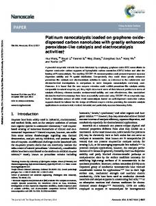
Fig. 1 Two alternative hypotheses for the observed reduction in symmetry in the metal nanostructure. Top row: Deposition occurs asymmetrically to produce a “single diamond” metal network (green). Bottom row: Deposition occurs symmetrically, producing two interlinked metal networks (green and blue) with a “double diamond” symmetry; on removal of the template, lateral “shifting” movement (in this case, of the blue network) causes a reduction in symmetry. Red squares represent a face of a crystallographic unit cell.
relative to one another, which would also produce a reduction in symmetry. Such a phenomenon has recently been reported in silica and titania networks, producing what the authors describe as a “shifted double diamond” structure.22 The two hypotheses are shown schematically in Fig. 1. While TEM images consistent with a single diamond structure suggest the former explanation,19 the technique inherently only shows those regions of the sample which are thin and open enough to allow a clear nanostructured pattern to be seen; it is therefore in principle possible that double diamond interlinked networks simply appeared black (as did the bulk of thicker fragments) and we only observed clear patterns from the fragments of a single diamond which had become free from the corresponding other network. In order to definitively distinguish these two hypotheses, we have carried out in situ SAXS measurements of electrodeposition of the platinum nanostructure in a QD II template, to determine whether the platinum itself grows in a single channel (i.e. with the Fd3m symmetry) or in both channels, which would represent the Pn3m symmetry, only changing to a lower symmetry when the lipid template is removed and the networks are free to move relative to one another. Our experiments also shed light on other observed features of the final metal nanostructure: the metal shows relatively broad Bragg peaks, in contrast to the very sharp peaks from the lipid,19 indicating greater lateral disorder; and our subsequent studies23 showed that, for thin (98.3% was purchased from Adina Cosmetics. Chloroplatinic acid (Dihydrogen hexachloroplatinate(2–)) solution (8% w/w in water) was purchased from Sigma. Thin gold foil (12.5 µm × 10 mm × 0.5 mm) purchased from Goodfellow was used as a substrate for electrodeposition. Nanostructured platinum films were deposited through the thin films of dip coated phytantriol as previously demonstrated by Akbar et al.19 The lipid template was applied by dip coating in a solution of ethanol and 60% (w/w) phytantriol. Once the template was applied, the substrates were left for half an hour in air in order for the solvent to evaporate, leaving a thin film of phytantriol on the electrode surface, estimated to be 16 ± 0.3 µm in thickness.28 Platinum films were deposited in a custom 3D printed acrylonitrile butadiene styrene (ABS) electrochemical cell on the beamline I07 at Diamond Light Source.29 The cell had Kapton windows and a path length of 7 mm to allow for X-ray transmission. The gold foil substrate was attached to a custom 3D
This journal is © The Royal Society of Chemistry 2017
View Article Online
Open Access Article. Published on 08 June 2017. Downloaded on 01/12/2017 23:59:39. This article is licensed under a Creative Commons Attribution 3.0 Unported Licence.
Nanoscale
printed holder using adhesive copper tape; this held the substrate in place perpendicular to the beam allowing for out-ofplane structural measurements typically by GISAXS or reflective SAXS. In addition to stability, the copper tape allowed the substrate to easily connect to the potentiostat. The sample holder was produced with the same width as the inside dimensions of the cell allowing it to be held in place by the cell’s elasticity. A platinum mesh was used as a counter electrode which was placed at the bottom of the cell with the wire at resting in the corner of the cell. An Ag/AgCl electrode (concentration – 3 M KCl), diameter 5 mm, was used as a reference. Before deposition the substrate was submerged into the platinum salt solution for 10 minutes in order to allow for the lipid film to form a QD II phase. An Autolab 101 potentiostat with NOVA software was used to control the potential and measure the current at the working electrode. Platinum was deposited by a potential step from 0.6 V to −0.25 V. An exposure of 1 s was collected using a Pilatus 2 M detector every two minutes starting five minutes before the reducing potential was applied, using X-rays with an energy of 13 keV and a beam size of 200 µm × 200 µm. A sample of silver behenate was used as a calibrant in order to measure the sample to detector distance and determine the beam centre. Radial and azimuthal profiles were produced from 2D SAXS images using YAX,30 a custom macro that runs within the ImageJ software package.31 For azimuthal integrations, 0° was defined as the 3 o’clock position with the angle increasing in the clockwise direction. Phases were identified by assigning peaks measured to Bragg reflections for a given phase. Predicted azimuthal angles were produced using previously published calculations32,33 listed in S1.† The amount of nanostructured platinum deposited was estimated by integrating the area of the √3 platinum peak observed at 1/d = 0.0125 Å−1.
Paper
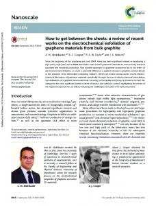
Fig. 2
Schematic of the in situ deposition set-up.
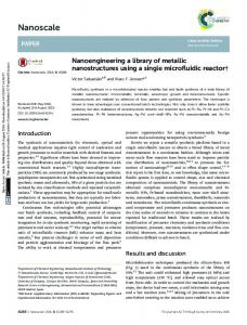
Results and discussion A custom electrochemical cell (as shown in Fig. 2) which allowed for in situ SAXS measurements of the working electrode was used to investigate the lipid templated nanostructure deposition process. A 1 s image was taken every 120 s of the working electrode, a phytantriol coated gold foil substrate, during the platinum electrodeposition. Stacked radial profiles are shown in Fig. 3; 1D SAXS data are stacked with respect to the deposition time, where 0 s is defined as the time when the reducing potential of −0.25 V was applied. Initially, before a potential is applied, only the signal from the lipid can be seen, where the √2, √3, √4, √6 Bragg peaks indexed to the Pn3m space group (QD II phase) are observed. The lattice parameter of the lipid was a = 70.36 ± 0.02 Å. From 0 s, a potential of −0.25 V is applied and a new peak is observed to appear at 0.0125 Å−1 due to the growing platinum nanostructure. This peak can be identified as the √3 peak of the Fd3m phase from the 2D images which will be discussed later. The lattice parameter of the platinum film was found to be 137 ± 2 Å. This would correspond to
This journal is © The Royal Society of Chemistry 2017
Fig. 3 Stacked SAXS radial intensity profiles for the phytantriol coated substrate taken during electrodeposition of platinum, plotted on a log intensity scale and stacked with respect to the time at which the image was taken relative to the start of deposition. The Bragg peaks belonging to the lipid and platinum films are labelled.
asymmetric deposition through a single channel network of a double diamond structure of lattice parameter a = 68.5 Å which agrees with our observations of the lipid and previous literature.19 This plot demonstrates an in situ SAXS measurement of the growth of the nanostructured film whilst simultaneously monitoring the lipid template. It also confirms that the Fd3m symmetry is present as the metal grows with a single diamond structure, rather than emerging from the lateral movement of two networks in a double diamond after template removal.
Nanoscale, 2017, 9, 10227–10232 | 10229
View Article Online
Open Access Article. Published on 08 June 2017. Downloaded on 01/12/2017 23:59:39. This article is licensed under a Creative Commons Attribution 3.0 Unported Licence.
Paper
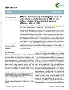
We have suggested19 a potential mechanism for the asymmetric growth of platinum in a QD II lipid cubic phase template due to greater accessibility to platinum ions dissolved in the external aqueous solution of one network than the other; this is based on the previously hypothesised model34 that in order to preserve bilayer topology at the surface of the cubic phase, one of the two networks of water channels becomes closed to the outside aqueous region. There is no direct proof of this phenomenon, but several pieces of evidence have recently emerged that support the suggestion: first, the AFM image of the QD II /water interface shows features with spacing consistent with a single network;35 second, the adopted QD II orientation with the (111) planes parallel with the surface is consistent with the expected lowest energy orientation considering the curvature of closed bilayer surfaces;33 finally, addition of a small amount of a pore-forming protein, which allows connectivity between the two networks, was found to greatly increase the rate of glucose release from cubic phases;36 this would not be expected if both networks were already connected to the external water region. The width of the emerging platinum peak demonstrates that the greater lateral disorder compared with the lipid template is present as the film grows, rather than being induced by template removal. We carried out offline deposition at different potentials, which produce different deposition rates, to see if it is possible to produce more highly ordered platinum with sharper SAXS peaks, but found no significant change in the peak width with the deposition potential (see ESI S3†) Fig. 4a shows how the integrated intensity of the platinum SAXS peak evolves over time, which can be correlated with the charge passed as shown in Fig. 4b. The intensity of a Bragg reflection is usually dependent upon the amount of the scattering material so this value would be expected to be proportional to the amount of nanostructured platinum deposited. It can be seen from the plot that the intensity of the platinum peak rapidly increases during the initial deposition, increases more slowly after 500 s (2 C cm−2 passed), and then reaches a plateau after 1500 s (9 C cm−2 passed). After this point, the peak does not increase despite the passage of further current. This may be because the increasing orientational disorder (see later) provides domains that do not satisfy the Bragg condition. However, we cannot rule out other potential explanations, such as the possibility that no further platinum is being deposited and the current instead is driving other electrochemical processes, or else because platinum is being deposited in a form which is not nanostructured, for example outside of the lipid template, although we note that in our previous work the thickness of films of comparable charge density was found to be up to 3.3 ± 0.2 µm (ref. 23) compared with the lipid template thickness23 of approximately 16 μm;19 this fact, coupled with the relatively smooth behaviour of the deposition charge density, makes these options less likely. The 2D SAXS images allow the orientation of the films to be studied in addition to the growth rates. Fig. 5 shows the 2D SAXS images obtained during the deposition process, together with the 1D azimuthal profiles of the inner platinum √3
10230 | Nanoscale, 2017, 9, 10227–10232
Nanoscale
Fig. 4 Evolution over time of the intensity of the platinum SAXS peak at 1/d = 0.0125 Å1 during the electrodeposition of platinum (a), charge density (b) and defined orientation value of the platinum film with the (111) facet parallel to the substrate (c).
reflection in an annulus from 1/d = 0.012–0.013 Å−1. From the 2D images, it can be observed that the innermost reflection, arising from the platinum structure, does not feature uniform intensity which indicates that the platinum structure is oriented. The 1D azimuthal profiles are plotted with dotted lines showing the predicted azimuthal angles for a Fd3m structure with the (111) plane oriented parallel to the substrate (see ESI S1† for calculations). It can be observed that initially the film is highly oriented in this fashion, after continuous deposition the film becomes more disordered. The outer two rings correspond to the lipid template and can be observed to be
This journal is © The Royal Society of Chemistry 2017
View Article Online
Open Access Article. Published on 08 June 2017. Downloaded on 01/12/2017 23:59:39. This article is licensed under a Creative Commons Attribution 3.0 Unported Licence.
Nanoscale
Paper
template and a previously reported platinum nanostructure with the template removed;23 images were radially integrated in wedges of 25° extending from the centre along the x- and y-axes, chosen to integrate over the on- and off-axis reflections, respectively. For the structure with the template still in place, the position of the peaks integrated from wedges taken in the x and y directions were found to agree within experimental uncertainty. Conversely, in our previous study, the off axis reflections (azimuthal angle = 71°, 109°, 251° and 289°) were found at greater 1/d values to the on axis reflections (0° and 180°) for a platinum structure with the template removed. This indicates that the film is deposited with cubic symmetry, where α = 90°, and that the previously observed elongation occurs after the removal of the template. A similar distortion was observed for platinum films deposited in gyroid block copolymer templates.1 Such distortions, while unlikely to impact significantly on the catalytic properties of nanomaterials, may affect optical properties in more exotic metamaterials.37
Conclusions
Fig. 5 2D SAXS images taken during electrodeposition (left) with the 1D azimuthal profile of the inner ring which arose from the deposition of platinum (right) after 153 s (a.), 516 s (b.) and 1242 s (c.).
uniform in intensity, indicating a polydomain structure with no overall alignment. This indicates that aligned platinum films are being produced from overall polydomain lipid templates. This agrees with our previous report where we concluded that there was an orientated region of the polydomain lipid close to the substrate interface. Platinum grown in the surface orientated polydomain film will initially be orientated as the lipid film but as more charge is passed and the film becomes thicker this order will gradually be lost. In order to quantify how well ordered the platinum films were with the (111) aligned parallel to the substrate, the average intensity at each of the predicted azimuthal angles taken from the 1D azimuthal profiles was divided by the overall average intensity. This orientation value would be 1 for a completely un-oriented sample, and increase as the sample became more ordered. Fig. 4c shows the orientation as defined plotted over time. This plot demonstrates more clearly that the films are initially oriented, and become disordered after a potential has been applied for 1200 s. In a previous report, we studied these aligned platinum films after the removal of the lipid template. It was observed that these structures had undergone distortion perpendicular to the plane of the electrode, resulting in a non-cubic structure, where α = 87° (α = 90° for cubic structures). Wedged radial integrated profiles are shown in S3† for an image of the platinum structure obtained in situ coexisting with the lipid
This journal is © The Royal Society of Chemistry 2017
In conclusion, we present an in situ SAXS measurement of the growth of nanostructured platinum films, and demonstrate that asymmetric deposition gives rise to the final Fd3m structure. This asymmetry enabled us to monitor both the structure of platinum deposition and the lipid template, as well as the charge passed during electrodeposition, and therefore the lateral and orientational ordering of the platinum and lipid films during deposition which could be correlated with the deposition charge passed. The technique can be extended to other materials templated from a lipid cubic phase system, and this represents the first time a study has been able to monitor structurally both the template and deposit during the deposition of a mesoporous film.
Acknowledgements SR was funded by the Diamond Light Source and a University of Reading Faculty Studentship. We thank Diamond for the provision of the beam time under experiment number SI10330-1.
Notes and references 1 J. Kibsgaard, Y. Gorlin, Z. Chen and T. F. Jaramillo, J. Am. Chem. Soc., 2012, 134, 7758–7765. 2 E. A. Franceschini, M. M. Bruno, F. J. Williams, F. A. Viva and H. R. Corti, ACS Appl. Mater. Interfaces, 2013, 5, 10437– 10444. 3 V. Mamaeva, J. M. Rosenholm, L. T. Bate-Eya, L. Bergman, E. Peuhu, A. Duchanoy, L. E. Fortelius, S. Landor, D. M. Toivola, M. Linden and C. Sahlgren, Mol. Ther., 2011, 19, 1538–1546.
Nanoscale, 2017, 9, 10227–10232 | 10231
View Article Online
Open Access Article. Published on 08 June 2017. Downloaded on 01/12/2017 23:59:39. This article is licensed under a Creative Commons Attribution 3.0 Unported Licence.
Paper
4 A. Walcarius, Electroanalysis, 2015, 27, 1303–1340. 5 X. Niu, H. Zhao, M. Lan and L. Zhou, Electrochim. Acta, 2015, 151, 326–331. 6 L. Peng, Y. Feng, Y. Bai, H.-J. Qiu and Y. Wang, J. Mater. Chem. A, 2015, 3, 8825–8831. 7 U. Bach, D. Lupo, P. Comte, J. E. Moser, F. Weissörtel, J. Salbeck, H. Spreitzer and M. Grätzel, Nature, 1998, 395, 583–585. 8 F. Sauvage, D. Chen, P. Comte, F. Huang, L.-P. Heiniger, Y.-B. Cheng, R. A. Caruso and M. Graetzel, ACS Nano, 2010, 4, 4420–4425. 9 Y. Ye, C. Jo, I. Jeong and J. Lee, Nanoscale, 2013, 5, 4584– 4605. 10 M. R. J. Scherer, P. M. S. Cunha and U. Steiner, Adv. Mater., 2014, 26, 2403–2407. 11 Y. Doi, A. Takai, Y. Sakamoto, O. Terasaki, Y. Yamauchi and K. Kuroda, Chem. Commun., 2010, 46, 6365–6367. 12 S. C. Warren, M. R. Perkins, A. M. Adams, M. Kamperman, A. A. Burns, H. Arora, E. Herz, T. Suteewong, H. Sai, Z. Li, J. Werner, J. Song, U. Werner-Zwanziger, J. W. Zwanziger, M. Grätzel, F. J. DiSalvo and U. Wiesner, Nat. Mater., 2012, 11, 460–467. 13 G. S. Attard, Science, 1997, 278, 838–840. 14 L. Omer, S. Ruthstein, D. Goldfarb and Y. Talmon, J. Am. Chem. Soc., 2009, 131, 12466–12473. 15 D. Wang, H. Luo, R. Kou, M. P. Gil, S. Xiao, V. O. Golub, Z. Yang, C. J. Brinker and Y. Lu, Angew. Chem., 2004, 116, 6295–6299. 16 E. J. W. Crossland, M. Kamperman, M. Nedelcu, C. Ducati, U. Wiesner, D. M. Smilgies, G. E. S. Toombes, M. a. Hillmyer, S. Ludwigs, U. Steiner and H. J. Snaith, Nano Lett., 2009, 9, 2807–2812. 17 H. Wang, H. Y. Jeong, M. Imura, L. Wang, L. Radhakrishnan, N. Fujita, T. Castle, O. Terasaki and Y. Yamauchi, J. Am. Chem. Soc., 2011, 133, 14526– 14529. 18 C.-F. Cheng, H.-Y. Hsueh, C.-H. Lai, C.-J. Pan, B.-J. Hwang, C.-C. Hu and R.-M. Ho, NPG Asia Mater., 2015, 7, e170. 19 S. Akbar, J. M. Elliott, M. Rittman and A. M. Squires, Adv. Mater., 2013, 25, 1160–1164.
10232 | Nanoscale, 2017, 9, 10227–10232
Nanoscale
20 V. Luzzati, H. Delacroix, A. Gulik, T. Gulik-Krzywicki, P. Mariani and R. Vargas, in Current Topics in Membranes, Academic Press, 1997, vol. 44, pp. 3–24. 21 A. M. Seddon, G. Lotze, T. S. Plivelic and A. M. Squires, J. Am. Chem. Soc., 2011, 133, 13860–13863. 22 H. Li, Y. Liu, X. Cao, L. Han, C. Jiang and S. Che, Angew. Chem., Int. Ed., 2016, 806–811. 23 S. J. Richardson, M. R. Burton, P. A. Staniec, I. S. Nandhakumar, N. J. Terrill, J. M. Elliott and A. M. Squires, Nanoscale, 2016, 8, 2850–2856. 24 D. J. Tobler, S. Shaw and L. G. Benning, Geochim. Cosmochim. Acta, 2009, 73, 5377–5393. 25 J. Polte, T. T. Ahner, F. Delissen, S. Sokolov, F. Emmerling, A. F. Thünemann and R. Kraehnert, J. Am. Chem. Soc., 2010, 132, 1296–1301. 26 P.-P. E. A. de Moor, T. P. M. Beelen and R. A. van Santen, J. Phys. Chem. B, 1999, 103, 1639–1650. 27 M. Tiemann, M. Fröba, G. Rapp and S. S. Funari, Chem. Mater., 2000, 12, 1342–1348. 28 S. Akbar, PhD thesis, University of Reading, 2012. 29 C. Nicklin, T. Arnold, J. Rawle and A. Warne, J. Synchrotron Radiat., 2016, 23, 1245–1253. 30 S. L. Gras and A. M. Squires, Methods Mol. Biol., 2011, 752, 147–163. 31 C. A. Schneider, W. S. Rasband and K. W. Eliceiri, Nat. Methods, 2012, 9, 671–675. 32 M. Rittman, H. Amenitsch, M. Rappolt, B. Sartori, B. M. D. O’Driscoll and A. M. Squires, Langmuir, 2013, 29, 9874–9880. 33 S. J. Richardson, P. A. Staniec, G. E. Newby, N. J. Terrill, J. M. Elliott, A. M. Squires and W. T. Góźdź, Langmuir, 2014, 30, 13510–13515. 34 K. Larsson, Curr. Opin. Colloid Interface Sci., 2000, 5, 64–69. 35 M. Rittman, M. Frischherz, F. Burgmann, P. G. Hartley and A. Squires, Soft Matter, 2010, 6, 4058. 36 A. Zabara, R. Negrini, O. Onaca-Fischer and R. Mezzenga, Small, 2013, 9, 3602–3609. 37 J. A. Dolan, B. D. Wilts, S. Vignolini, J. J. Baumberg, U. Steiner and T. D. Wilkinson, Adv. Opt. Mater., 2014, 3, 12–32.
This journal is © The Royal Society of Chemistry 2017