Published on 07 September 2015. Downloaded by Korea Institute of Machinery & Materials (KIMM) on 01/10/2015 02:49:27.
Nanoscale COMMUNICATION
Cite this: DOI: 10.1039/c5nr02602d Received 22nd April 2015, Accepted 29th August 2015 DOI: 10.1039/c5nr02602d www.rsc.org/nanoscale
View Article Online View Journal
Electrospun ion gel nanofibers for flexible triboelectric nanogenerator: electrochemical effect on output power† Byeong Uk Ye,a Byoung-Joon Kim,b Jungho Ryu,c Joo Yul Lee,b Jeong Min Baik*a and Kihyon Hong*b
A simple fabrication route for ion gel nanofibers in a triboelectric nanogenerator was demonstrated. Using an electrospinning technique, we could fabricate a large-area ion gel nanofiber mat. The triboelectric nanogenerator was demonstrated by employing an ion gel nanofiber and the device exhibited an output power of 0.37 mW and good stability under continuous operation.
An ionic liquid that consists of low molar mass cations and anions has attracted considerable attention in charge transport and in electrochemical experiments.1–3 To improve the processability of an ionic liquid for use in practical devices, it is desirable to blend ionic liquids with network-forming block copolymers, and the resulting materials are referred to as “ion gels”. Ion gels have exceptional physical properties, such as high ionic conductivity, short polarization time, good thermal stability and outstanding mechanical strength.4,5 As a result, ion gels are promising materials for use as an electrolyte for batteries, supercapacitors, organic/inorganic transistors, and electrochromic displays.6–8 Recently, the functionality of ion gels has been expanded to include flexible electrochemiluminescence.9 In most cases, ion gels are processed by spin coating or by direct write printing, and thus, they have either only bulk or 2D thin-film structures that, when compared to nano-wire/nano-dots structures, have a relatively small surface area and limited functionality.10,11 Thus, although there has been increased interest in ion gels in various research fields, their applications have been limited to electrolyte materials in battery/capacitors and in gate insulating materials in transisa School of Mechanical and Advanced Materials Engineering, Ulsan National Institute of Science and Technology (UNIST), Ulsan 689-798, Republic of Korea. E-mail:
[email protected] b Surface Technology Division, Korea Institute of Materials Science (KIMS), Changwon, 641-831, Republic of Korea. E-mail:
[email protected] c Functional Ceramic Group, Korea Institute of Materials Science (KIMS), Changwon, 641-831, Republic of Korea † Electronic supplementary information (ESI) available: I. Experimental section. II. FTIR and XRD spectra of ion gel nanofiber. III. Output voltage of TENG with various polymer nanofibers. IV. Output voltage of TENG under different connection types. V. Output voltage of TENG with 20 wt% ion gel nanofibers. See DOI: 10.1039/c5nr02602d
This journal is © The Royal Society of Chemistry 2015
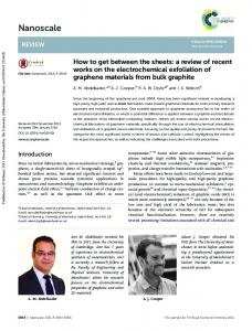
tors. To the best of our knowledge, there is no report on the formation of electrospun ion gels with a nanofiber structure and on their applications as active materials in energy harvesting devices. Various kinds of nanogenerators have been reported, and of these, triboelectric nanogenerators (TENG) have attracted considerable attention due to their high energy efficiency, simplicity, and scalability.12–14 The operation principle of a TENG is based on coupling with an electrostatic effect. Fig. 1a–c shows the working principle of TENG with polymer ( poly(vinylidene fluoride-co-hexafluoropropylene), P(VDF-HFP)) and Kapton layers. Initially, no charge is inducted with no electric potential difference between two electrodes of P(VDF-HFP) based TENGs (Fig. 1a). When an external compressive force is applied, the P(VDF-HFP) and Kapton is brought into contact with each other. Surface charge transfer then takes place at the interfaces as a result of the triboelectric effect. According to the triboelectric series, a Kapon film has strong negative triboelectric polarity.15 Thus, negative and positive charges are induced at the Kapton and P(VDF-HFP) surfaces, respectively. Owing to the insulating properties of P(VDF-HFP) and Kapton, the transferred charges are confined at each surface, leading to no electric potential difference between the two electrodes (Fig. 1b). When the pressure is released, the P(VDF-HFP) and Kapton
Fig. 1 Simplified schematic diagram of the electric power generation process of (a–c) bare P(VDF-HFP) and (d–f ) ion gel based triboelectric nanogenerators. Diagrams are not to scale.
Nanoscale
View Article Online
Published on 07 September 2015. Downloaded by Korea Institute of Machinery & Materials (KIMM) on 01/10/2015 02:49:27.
Communication
surfaces are separated from each other. At this stage, the dipole moment becomes stronger and a strong electric potential difference is generated between the electrodes. Thus, electrons begin to flow from a negative to positive potential, and charge accumulates on the electrodes, resulting in a positive electrical signal (Fig. 1c). The physical properties of triboelectric materials, such as the surface roughness, electron affinity, friction, and capacitance, affect the performance of TENG, and a high capacitance is needed to improve the output performance of the devices in terms of the output voltage and current.15,16 Ion gels have previously been reported to form an electrical double layer (EDL) with a very high capacitance (>10 μF cm−2) by an externally applied bias.17,18 When an ion gel is employed as the triboelectric material in TENG and a compressive force is applied, the confined charges attract counterions. At the release stage, positive and negative ions accumulate at the air/ion gel and ion gel/electrode interfaces, forming a high capacitance 2D-EDL (Fig. 1d–f ). Thus, we can expect that the high capacitance EDL can remarkably improve the performance of TENGs. In this study, we have extended the functionality of ion gels to demonstrate the use of an electrical energy-harvesting TENG. To enhance the performance of the power output, we employed a nanofiber-structured ion gel as a triboelectric material. A conventional electrospinning technique was used to fabricate a large-area (16 cm × 16 cm) ion gel nanofiber mat with a thickness ranging from 10–1000 μm. We designed the TENG using a bare polymer ( poly(vinylidene fluoride-cohexafluoropropylene), P(VDF-HFP)) and ion gel nanofibers. The hompolymer, PVDF is insoluble in ionic liquids. To form a free-standing ion gel nanofiber mat, we employed P(VDF-HFP) as a matrix polymer, where -HFP acts as a crosslinking site for the gelation process. In the first step, we prepared TENGs using both of spin-coated P(VDF-HFP) film and electrospun P(VDF-HPF) nanofibers. Compared to a TENG with a spin-coated film (3 V and 5 μA cm−2), the device with a P(VDF-HFP) nanofiber structure fabricated via electrospinning showed an improved power output (20 V, 19 μA cm−2). This implies that the surface morphology of triboelectric layer is clearly an important factor for achieving high performance TENG. By doping ionic liquid 1-ethyl-3-methylimidazolium bis(trifluoromethylsufonyl)imide, [EMIM][TFSI] into P(VDF-HFP), we could fabricate ion gel nanofibers, and the output voltage and current from the TENG increases to a high value of 45 V and 49 μA cm−2, respectively, under the same cycled compressive force. When a compressive force is applied to the TENG with ion gels, positive and negative charges are generated by the triboelectric effect and attract counterions in the ion gels, and an EDL with a large capacitance (>10 μF cm−2) forms at the ion gel/electrode interfaces, resulting in an improvement in the power output. We also evaluated the device stability, and found that the ion gel nanofiber-based TENGs exhibited good stability under continuous operation over 10 000 cycles. Overall, the results indicate that the nanofiber-structured ion gel provides a convenient route to incorporate an active layer in energy harvesting devices.
Nanoscale
Nanoscale
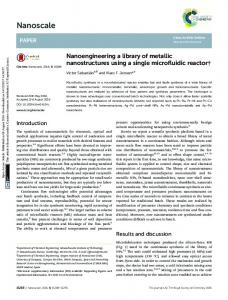
In the TENG device, the large surface area and rough surface of the triboelectric layer can generate a greater surface charge through the triboelectric effect, resulting in a high power output.19,20 Thus, in this work, we fabricated nanofiberstructured ion gels via electrospinning to improve the triboelectric effect. The electrospinning technique is a simple and effective method that is capable of fabricating polymer nanofibers with diameters down to a few nanometers, and the electrospinning setup itself consists of an ion gel solution container, a syringe pump, a grounded collector, and a highvoltage power supply, as shown in Fig. 2a and b.21,22 At a high DC voltage (electric field), the surface of the solution was highly charged, and a number of ion gel jets were generated. These jets moved and were deposited on the collector, forming nanofiber structures. Aluminium foil was placed on the collector plate to act as the receiver substrate, and by controlling the collection time, we can control the area and thickness of the ion gel nanofibers. The collection time to produce a 50 μmthick ion gel nanofiber mat with a 16 cm × 16 cm area was about 40 min (Fig. 2c). The thickness was measured using a micrometer. Fig. 2d schematically illustrates the structure of the TENG with the ion gel nanofibers. To fabricate the TENG, we used Al foil and Kapton coated Al film as the bottom and top electrodes, respectively. Ion gel nanofiber mat was electrospun on the bottom electrode. To form a narrow air gap between the ion gel nanofiber mat and Kapton/Al electrode we attached a spacer, insulating polymer film (double side Kapton tape) on the nanofiber mat surface.23 The ion gel
Fig. 2 (a) Schematic diagram of the electrospinning set-up used in this study. (b) Digital image of the electrospinning process used for fabrication of the ion gel nanofibers. The fibers were collected on the surface of a collector covered with aluminium foil. (c) Image of a large piece of 50 μm-thick ion gel nanofiber mat prepared via electrospinning (16 cm × 16 cm, scale bar: 2 cm). (d) Structure and an illustration of the triboelectric nanogenerator with ion gel nanofibers. Diagrams are not to scale.
This journal is © The Royal Society of Chemistry 2015
View Article Online
Published on 07 September 2015. Downloaded by Korea Institute of Machinery & Materials (KIMM) on 01/10/2015 02:49:27.
Nanoscale
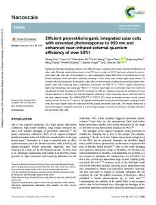
nanofiber mat and top electrode were then connected using the polymer spacer, leaving a 1 mm space. Fig. 3a–d show scanning electron microscopy (SEM) images of electrospun ion gel nanofibers with different ionic liquid concentrations (0, 2, 5, and 10 wt%). For example, a 10 wt% ion gel was prepared by adding 0.1 g of ionic liquid and 0.9 g of P(VDF-HFP) to a solvent. Smooth and bead-free solid fibers that formed a randomly-oriented fiber web were obtained for all the samples. As the ionic liquid concentration increased, the shape of the nanofibers for each sample did not present any noticeable changes. However, slight changes in the diameters of the nanofibers and in the distribution were found. The average diameter of the 0 wt% sample (bare P(VDF-HFP)) was 482 ± 160 nm. For the 10 wt% ion gel sample, the average diameter decreased to 457 ± 192 nm. This is due to an increase in the charge density in the solution containing anions and cations, which causes the induction charges on the surface of nanofibers under the same electric field. During electrospin-
Fig. 3 (a–d) SEM images of electrospun ion gel nanofibers composed of poly (vinylidene fluoride-hexafluoropropylene) (P(VDF-HFP)) and different doping ratios of ionic liquid, 1-ethyl-3-methylimidazolium bis(trifluorosulfonyl)imide ([EMIM][TFSI]) (0–10 wt%). Scale bar: 1 μm. (e–h) The bar charts show the fiber diameter distribution of electrospun ion gel as a function of the doping concentration. The average diameter of the P(VDF-HFP) (0 wt%) and ion gel (10 wt%) sample were 482 nm and 457 nm, respectively.
This journal is © The Royal Society of Chemistry 2015
Communication
ning, the jet is stretched and bent due to the interaction between the elastic forces and the applied electronic field.24,25 As the ions in the ion gel induce high charge densities to the jet, bending instabilities occur at high concentration samples, resulting in a reduced diameter and in a wide diameter distribution. X-ray diffraction (XRD) and Fourier transform infrared (FTIR) spectroscopy were performed on each sample to investigate the crystalline structure of the ion gel nanofiber. As plotted in Fig. S1a,† all samples showed semi-crystalline polymer characteristics, and there was one peak at about 20.5° 2θ, corresponding to the (110) crystal planes, implying all samples have a β-phase microstructure.26 The change in microstructure can be observed in FITR spectra. For 0 wt%-sample, we can find characteristic peaks related β-phase at 1276 and 841 cm−1 and very weak shoulder peak related γ-phase at 1232 cm−1. The 2 wt%-sample showed similar spectrum to that of 0 wt%-sample. As the ionic liquid concentration increased, the peak intensity at 1276 cm−1 decreased drastically and α-phase related peaks newly appeared at 1152, 796, and 613 cm−1.27 Several peaks also appeared in the region between 1348, 1132, 500, and 750 cm−1, corresponding to the [EMIM][TFSI].28 These findings suggest that electrospun P(VDF-HFP) has the crystalline structure of a β-phase and a very small amount of γ-phase. With increasing ionic liquid concentration (2, 5, 10 wt% samples), the ions in the ionic liquid cause local induction charges on the surface of the nanofibers to flow longitudinally and become neutralized in the fiber, consequently reducing the polarizability of the P(VDF-HFP) nanofibers. Fig. 4a and b show the output voltage and current density, generated by the P(VDF-HFP) nanofiber-based TENG under a cycled compressive force of 50 N at an applied frequency of 5 Hz. To compare the output performance of the nanofiberstructured mat with that of flat films, a nanogenerator with spin-coated P(VDF-HFP) triboelectric materials (flat surface) was also fabricated and evaluated. Both devices generated an typical AC-type signal, and the output voltages of the TENGs with a P(VDF-HFP) nanofiber structure and of those with a flat surface were 20 V and 3 V, respectively, under the same mechanical forces. There was a 6.2 fold increase in current density. One of the advantages of electrospinning is that various kinds of polymer nanofibers can be fabricated.25 Thus, we also fabricated TENGs using electrospun polyvinyl pyrrolidone (PVP), polystyrene (PS) and polymethyl methacrylate (PMMA) nanofibers, and these also exhibited typical TENG output performance (ESI Fig. S2†). The PVDF and P(VDF-HFP) are well-known piezoelectric materials that generate dipole moments by an externally applied pressure.29 In this work, we believe that the piezoelectric effect can be ruled out as a possible reason for the electrical output of the TENGs for the following reasons: (1) to harvest the electrical power from piezoelectric property of P(VDF-HFP), the external force applied to the material and the change in the dipole orientation results in piezoelectricity. Thus, the typical piezoelectric nanogenerator has a sandwich structure (electrode/P(VDF-HFP)/electrode). In the case of
Nanoscale
View Article Online
Published on 07 September 2015. Downloaded by Korea Institute of Machinery & Materials (KIMM) on 01/10/2015 02:49:27.
Communication
Fig. 4 (a) Output voltage and (b) current density of the TENG composed of spin coated P(VDF-HFP) film and electrospun nanofibers. The active area of the device was 1 cm × 1 cm. (c–d) The electrical output performance of the ion gel nanofiber-based TENG with various ionic liquid doping concentrations (0–10 wt%) under the same mechanical force (50 N) and frequency ( f = 5 Hz).
TENG, repeated contacting and releasing of two different materials results in induced surface charge and generates electrical power due to the large difference in the ability to attract electrons. In our work, we generated electrical power by contacting and releasing two different materials, P(VDF-HFP) and Kapon coated Al electrode (electrode/P(VDF-HFP)/air gap/ Kapton/electrode). Thus, we believe that the triboelectric effect dominantly contributes to generate electrical power in our system. (2) It is known that the typical output voltage and current of piezoelectricity (V = 1–5 V) are only about 10% of the triboelectric output (V = 10–300 V) under the same contact conditions.29 In this work, our P(VDF-HFP) and other nonpiezoelectric polymers (PS, PMMA, PVP) showed nanogenerator characteristics with an output voltage over 20 V. Such a large output voltage means that the influence of piezoelectricity on the electrical output of our TENGs is negligible. For these reasons, we can conclude that the output power of the nanogenerator originates from the triboelectric effect of ionic liquid doped P(VDF-HFP), and this ion gel nanofibers prepared via electrospinning are effective in improving the output
Nanoscale
Nanoscale
performance of TENG. To confirm that the measured output performance originated from the TENG and to eliminate the influence of the noise caused by the measuring system, we changed the method for connecting the device (switching polarity) with the measurement equipment (ESI, Fig. S3†). The connecting configuration that had a positive probe connected to the P(VDF-HFP) nanofibers and a negative probe connected to the Kapton film is defined as a forward connection, and the inverted connection is defined as the reverse connection.12 When we reversed the connection of the voltage and current meters, the output signals were reversed, as shown in Fig. S3,† implying that the output signals were generated by a triboelectric effect. When we employed electrospun ion gel nanofibers instead of bare P(VDF-HFP), the device presented improved output performance (Fig. 3c and d). For the 2 wt%-device, the output voltage and the current density reached 42 V and 38 μA cm−2, respectively. The values increased to 45 V and 49 μA cm−2 for the 10 wt%-device. To investigate the effective electric power (P) of the TENG, the resistors were connected as external loads (ESI S4†). The power output (P = I2R) of 0 wt%-TENG reached the maximum value of 0.14 mW at a load resistance of 100 MΩ, and the value increased to 0.37 mW for 10 wt%device. The improvement in the electrical power generated by doping the ionic liquid can be explained by the increase in the inductive charges and capacitance in the triboelectric layer. The output voltage (Vout) of TENG is an open circuit voltage depending on the amount of electrons that flow between two electrodes. Our TENG is composed of three regions, ion gel, air gap and Kapton. The voltage at each region is a function of the electric field (E) and thickness (d ) of the layer (V = Ed ). Thus, the Vout, can be given by the summation of Viongel, Vair and VKapton (Vout = Viongel + Vair + VKapton).30 Considering the thickness of each region (dKapton = 5 × 101 μm, dair = 103 μm, and dKapton = 1 × 102 μm), the Viongel would be much smaller than Vair. This Viongel at the ion gel can attract mobile counterions in the ion gels, leading to the formation of an EDL at the ion gel/electrode and air/ion gel interfaces. Because this EDL exhibits a layer thickness of a few nanometers, the ideal capacitance of the EDL had previously been reported to be very large at about >10 μF cm−2.18 We calculated the triboelectric charge density (σ) using the equation, σ = Vε0/dair, where ε0 and dair are the vacuum permittivity and spacer height, respectively, and a larger σ value (13.3 C m−2) for the ion gel-based TENG than for the of P(VDF-HFP) based one (5.2 C m−2) might originate from the formation of EDL. A current (I) that is generated across the TENG is a function of the voltage (V) across two electrodes and the change in the capacitance (C) of the system,15 I¼C
@V @C þV @t @t
Thus, the mobile ions in the ion gel nanofiber mat form a large capacitance EDL and increase the capacitance of TENGs, leading to an enhancement in the output current and power. This result implies that the EDL formed by electrochemical
This journal is © The Royal Society of Chemistry 2015
View Article Online
Published on 07 September 2015. Downloaded by Korea Institute of Machinery & Materials (KIMM) on 01/10/2015 02:49:27.
Nanoscale
effect in the ion gel nanofibers plays an important role in increasing the capacitance of the triboelectric layer, resulting in an improvement in the output performance of TENGs. The 20 wt%-TENG device presented a much reduced output voltage and current (ESI Fig. S5†). This result can be explained by the triboelectric material-to-electrolyte transition in the ion gel nanofibers. The output power data in Fig. 4 suggests that the ion gel nanofibers behave as a triboelectric material for ionic liquid concentrations of up to 10 wt%. Above this concentration, the output power of the generator is degraded drastically, indicating that the ion gel nanofibers act as an electrolyte. To have a clear understanding of this finding, considerably more investigation will be needed. We performed a durability/stability test of the ion gel-based TENG (10 wt%) to confirm the mechanical stability of the device. Fig. 5a and b show the output voltage and the current of a TENG operated continuously at 5 Hz for 10 000 cycles. After the test, the device still displayed clear power-generating performance. As plotted in Fig. 5c, only a slight decrease (∼5%) was observed for the output voltage after a total of 10 000 working cycles. This slight degradation in the performance of the TENG might originate from the deformation in the
Fig. 5 Operational stability of ion gel based TENG. (a) Voltage and (b) current characteristics of the TENG operated continuously for 10 000 cycles, acquired at f = 5 Hz. (c) Change in the output voltage of the TENG as a function of the operating cycle. Inset: change in the current for TENG and SEM images (100 μm × 100 μm) of ion gel nanofibers (10 wt%) surface before and after 10 000 cyclic operation. (d) A snapshot of a 15-LED array lit up by the power output generated from the TENG.
This journal is © The Royal Society of Chemistry 2015
Communication
surface morphology of the ion gel nanofibers. Before the test, the ion gel exhibited a clear nanofiber structure. After the test, however, the nanofibers were deformed by cyclic compressive stress (Inset in Fig. 5c). Although the surface of the ion gel nanofibers was deformed by the continuous cyclic stress, the output performance of the TENG could be maintained. To study a practical application of the TENG, we drove series-connected light emitting diodes (LEDs) using solely the power output from an ion gel based TENG. The red LEDs were connected directly to the output of the TENG without any capacitor and rectifier. Fig. 5d presents images taken after the TENG was activated. The power output of TENG (10 wt%) was able to instantaneously and simultaneously light up more than 15-LEDs. The P(VDF-HFP)-based TENG, however, lit up to 10 LEDs under the same compressive force (not shown here). These results confirm that ion gel nanofibers can be suitable for use in high performance TENG.
Conclusions In conclusion, we have successfully demonstrated the application of electrospun ion gel nanofibers as a triboelectric material for TENG. The novelty of this study lies in (1) the fabrication of large area ion gel nanofibers using a simple electrospinning method and (2) the first demonstration of an energy harvesting application of ion gel nanofibers using the triboelectric effect. With the electrospinning method, we fabricated a large area (16 cm × 16 cm) ion gel nanofiber mat, and the nanofibers had an average diameter of 457 nm. A large output voltage of up to 45 V and current density of up to 49 μA cm−2 could be obtained from the ion gel-based TENG compared to the electrical output obtained from the bare polymer P(VDF-HFP)-based device (20 V and 19 μA cm−2) under the same mechanical force. The improvement in the electrical power output of the ion gel-based TENG can be explained in terms of the formation of an EDL in the triboelectric materials. In addition, the TENG exhibited good stability under continuous operation. We could also power 15 LEDs using the electrical power output of the TENG without any other external energy source or rectifier. The excellent output performance and stability of this simple but effective nanofiber-structured ion gel opens up a new opportunity for applications to portable device power system and self-powered electronic systems. Future study will focus on achieving fabric-based energy devices and on developing practical power sources for electronic applications.
Acknowledgements This study was supported by the Korea Institute of Materials Science (KIMS) and Basic Science Research Program through the National Research Foundation of Korea (NRF) funded by the Ministry of Science, ICT & Future Planning (2012R1A1A104409).
Nanoscale
View Article Online
Communication
Published on 07 September 2015. Downloaded by Korea Institute of Machinery & Materials (KIMM) on 01/10/2015 02:49:27.
Notes and references 1 H. Zhong, F. Xu, Z. Li, R. Fu and D. Wu, Nanoscale, 2013, 5, 4678–4682. 2 Y. Lu, K. Korf, Y. Kambe, Z. Tu and L. A. Archer, Angew. Chem., Int. Ed., 2014, 53, 488–492. 3 C. Zhu, J. Zhai and S. Dong, Nanoscale, 2014, 6, 10077– 10083. 4 Y. Gu, S. Zhang, L. Martinetti, K. H. Lee, L. D. McIntosh, C. D. Frisbie and T. P. Lodge, J. Am. Chem. Soc., 2013, 135, 9652–9655. 5 K. H. Lee, S. Zhang, T. P. Lodge and C. D. Frisbie, J. Phys. Chem. B, 2011, 115, 3315–3321. 6 C. Yan, J. H. Cho and J.-H. Ahn, Nanoscale, 2012, 4, 4870– 4882. 7 K. H. Lee, M. S. Kang, S. Zhang, Y. Gu, T. P. Lodge and C. D. Frisbie, Adv. Mater., 2012, 24, 4457–4462. 8 X. Liu, D. Wu, H. Wang and Q. Wang, Adv. Mater., 2014, 26, 4370–4375. 9 H. C. Moon, T. P. Lodge and C. D. Frisbie, J. Am. Chem. Soc., 2014, 136, 3705–3712. 10 J. H. Cho, J. Lee, Y. Xia, B. Kim, Y. He, M. J. Renn, T. P. Lodge and C. D. Frisbie, Nat. Mater., 2008, 7, 900–906. 11 I. Lokteva, S. Thiemann, F. Gannott and J. Zaumseil, Nanoscale, 2013, 5, 4230–4235. 12 Y. Zheng, L. Cheng, M. Yuan, Z. Wang, L. Zhang, Y. Qin and T. Jing, Nanoscale, 2014, 6, 7842–7846. 13 K. Y. Lee, J. Chun, J. H. Lee, K. N. Kim, N. R. Kang, J. Y. Kim, M. H. Kim, K. S. Shin, M. K. Gupta, J. M. Baik and S. W. Kim, Adv. Mater., 2014, 26, 5037–5042. 14 Y. Yang, H. Zhang and Z. L. Wang, Adv. Funct. Mater., 2014, 24, 3745–3750.
Nanoscale
Nanoscale
15 F.-R. Fan, Z.-Q. Tian and Z. L. Wang, Nano Energy, 2012, 1, 328–334. 16 F. R. Fan, L. Lin, G. Zhu, W. Wu, R. Zhang and Z. L. Wang, Nano Lett., 2012, 12, 3109–3114. 17 S. H. Kim, K. Hong, K. H. Lee and C. D. Frisbie, ACS Appl. Mater. Interfaces, 2013, 5, 6580–6585. 18 S. H. Kim, K. Hong, W. Xie, K. H. Lee, S. Zhang, T. P. Lodge and C. D. Frisbie, Adv. Mater., 2013, 25, 1822–1846. 19 Y. Yang, Y. S. Zhou, H. Zhang, Y. Liu, S. Lee and Z. L. Wang, Adv. Mater., 2013, 25, 6594–6601. 20 S. Wang, L. Lin and Z. L. Wang, Nano Lett., 2012, 12, 6339– 6346. 21 Y. Liu, X. Zhang, Y. Xia and H. Yang, Adv. Mater., 2010, 22, 2454–2457. 22 J. H. Park and P. V. Braun, Adv. Mater., 2010, 22, 496–499. 23 S. Kim, M. K. Gupta, K. Y. Lee, A. Shon, T. Y. Kim, K.-S. Shin, D. Kim, S. K. Kim, K. H. Lee, H.-J. Shin, D.-W. Kim and S.-W. Kim, Adv. Mater., 2014, 26, 3918– 3925. 24 D. Li and Y. Xia, Adv. Mater., 2004, 16, 1151–1170. 25 A. Greiner and J. H. Wendorff, Angew. Chem., Int. Ed., 2007, 46, 5670–5703. 26 D. Saikia and A. Kumar, Electrochim. Acta, 2004, 49, 2581– 2589. 27 D. Mandal, K. Henkel and D. Schmeiber, Phys. Chem. Chem. Phys., 2014, 16, 10403–10407. 28 J. Kiefer, J. Fries and A. Leipertz, Appl. Spectrosc., 2007, 61, 1306–1311. 29 P. Bai, G. Zhu, Y. S. Zhou, S. Wang, J. Ma, G. Zhang and Z. L. Wang, Nano Energy, 2014, 7, 990–997. 30 S. Niu, S. Wang, L. Lin, Y. Liu, Y. S. Zhou, Y. Hu and Z. L. Wang, Energy Environ. Sci., 2013, 6, 3576–3583.
This journal is © The Royal Society of Chemistry 2015