IEEE TRANSACTIONS ON NEURAL NETWORKS, VOL. 12, NO. 5, SEPTEMBER 2001
1121
Neural-Network Control of Mobile Manipulators Sheng Lin and A. A. Goldenberg, Fellow, IEEE
Abstract—In this paper, a neural network (NN)-based methodology is developed for the motion control of mobile manipulators subject to kinematic constraints. The dynamics of the mobile manipulator is assumed to be completely unknown, and is identified on-line by the NN estimators. No preliminary learning stage of NN weights is required. The controller is capable of disturbance-rejection in the presence of unmodeled bounded disturbances. The tracking stability of the closed-loop system, the convergence of the NN weight-updating process and boundedness of NN weight estimation errors are all guaranteed. Experimental tests on a four-DOF manipulator arm illustrate that the proposed controller significantly improves the performance in comparison with conventional robust control. Index Terms—Closed-loop stability, disturbance rejection, dynamics interaction, mobile manipulator, neural networks (NNs), parameter uncertainty.
I. INTRODUCTION
A
MOBILE manipulator is a robotic arm mounted on a moving base. The base mobility substantially increases the size of the robot workspace, and enables better positioning of the manipulator for efficient task execution. Mobile manipulator systems have been suggested for various applications, e.g., tasks involving hazardous environments, such as explosive handling, waste management, outdoor exploration and space operations. The motion of the mobile base is subject to holonomic or nonholonomic kinematics constraints, which renders the control of mobile manipulator very challenging. Furthermore, the complex physical structure, the highly coupled dynamics between the mobile base and the mounted manipulator arm, and the mobility of the wheeled mobile base are some of the features that substantially increase the difficulty of system design and control. In recent years, there has been a growing interest in the motion control of mobile manipulators. Hootsmans and Dubowsky [1] developed a control method based on an extended Jacobian to compensate for dynamic interactions between the manipulator and base. Yamamoto et al. [2] addressed the coordination of locomotion and manipulator motion between the base and the arm, and the problem of following a moving surface. Liu and Lewis [3] developed a decentralized robust controller for trajectory tracking of the mobile manipulator end-effector. Khatib [4] addressed payload modeling and control issue. Tahboub [5]
Manuscript received April 11, 2000; revised December 7, 2000. S. Lin is with the Mechanical and Industrial Engineering Department, University of Toronto, Toronto, ON M5S 3G8, Canada (e-mail:
[email protected]). A. A. Goldenberg is with the Mechanical and Industrial Engineering Department, University of Toronto, Toronto, ON M5S 3G8, Canada. He is also with Engineering Services, Inc. (ESI), Toronto, ON, Canada (e-mail:
[email protected]). Publisher Item Identifier S 1045-9227(01)05537-0.
developed a robust adaptive controller for trajectory tracking of a mobile manipulator when it moves on uneven terrain. Chung et al. [6] proposed an interaction controller for the control of mobile manipulator, consisting of a robust adaptive manipulator controller and an input–output linearizing controller. Dixon et al. [18] developed a robust tracking and regulation controller for mobile robots. Most approaches require the precise knowledge of dynamics of the mobile manipulator, or, they simplify the dynamics model by ignoring dynamics issues, such as vehicle dynamics, payload dynamics, dynamics interactions between the base and the arm, and unknown disturbances such as the dynamic effect caused by terrain irregularity. These issues make the published schemes inappropriate for realistic applications for the following reasons. Due to its complexity, the precise dynamics model of a mobile manipulator is normally unobtainable. When the mobile manipulator moves at a relatively high speed, ignoring the vehicle dynamics and the dynamics interactions between the arm and the base may cause unbearable vibrations of the system [1]. Finally, when the robot moves on uneven terrain (e.g., for outdoor exploration), ignoring disturbances generated by terrain irregularities may lead to tip-over. In the recent years, neural networks (NNs), with their strong learning capability, have proven to be a suitable tool for controlling complex nonlinear dynamic systems. The basic idea behind NN-based control is to use an NN estimator to identify the unknown nonlinear dynamics and compensate for it. Also, the NN-based approach can deal with the control of nonlinear systems that may not be linearly parameterizable, as required in the adaptive approach. With regard to neural networks, they have been widely adopted in the modeling and control of robotic manipulators [7], [19]. Polycarpou [8] provided a systematic methodology for the identification of nonlinear systems using neural networks. Jin et al. [9] developed a strict theoretical basis for the stable design of NN-based manipulator control. Gorinevsky et al. [10] applied neural networks to path-planning and tracking control problems of mobile robots. Lewis et al. [7] proposed an NN control scheme that guarantees closed-loop performance in terms of small tracking errors and bounded controls. Fierro and Lewis [11] further applied this methodology to the control of a nonholonomic mobile robot where unmodeled bounded disturbances and/or unstructured unmodeled dynamics of the vehicle are considered. One main issue of all the contributions mentioned above is that the effectiveness was illustrated only through simulations. Very few results were reported to have been verified experimentally. Moreover, to the best of our knowledge, no satisfactory experimental results have been reported in the literature on NN-based stable closed-loop robotic control. Also, it is well
1045–9227/01$10.00 © 2001 IEEE
1122
IEEE TRANSACTIONS ON NEURAL NETWORKS, VOL. 12, NO. 5, SEPTEMBER 2001
known that good simulation performance of a control law normally does not guarantee its applicability in real systems due to unmodeled dynamics, difficulty in parameter adjustment or other limitations. In this paper, an NN-based control methodology is proposed for the joint-space position control of a mobile manipulator. Two NN controllers are developed to control the arm and the base independently. Each NN controller output comprises a linear control term (classical PID) and an NN compensation term. The NN compensation term is used for on-line estimation of unknown nonlinear dynamics caused by parameter uncertainty and disturbances. No preliminary learning stage is required for the NN weights. The control scheme is capable of disturbance-rejection in the presence of unknown bounded disturbances. The NN on-line learning laws are original. The tracking stability of the closed-loop system, the convergence of the NN learning process and the boundedness of NN weight estimation errors are all rigorously proven. In order to validate the proposed NN-controllers and NN learning laws, extensive experiments have been conducted on a real robotic manipulator. The experimental results are also presented in this paper. This paper is organized as follows. Section II provides some necessary mathematical preliminaries. The dynamic model of mobile manipulators subject to kinematic constraints is derived in Section III. The proposed theory is developed in Section IV. Section V presents the experimental results to illustrate the effectiveness of the proposed theory. Some remarks are made in the final Section VI.
there exists a bound for all
and a time .
, such that
III. DYNAMICS MODELING OF A MOBILE MANIPULATOR A. General The dynamics of a mobile manipulator subject to kinematic constraints can be obtained using the Lagrangian approach in the form [7] (6) where
kinematic constraints are described by (7)
denotes the generalized coordinates, is the symmetric and positive definite inrepresents the centripetal and ertia matrix, represents the friction and Coriolis matrix, is the constraint matrix, gravitational vector, is the Lagrange multiplier which denotes the vector of denotes bounded unknown disturconstraint forces, is bances including unstructured dynamics, is the torque the input transformation matrix, and input vector. In (6), the following properties hold [7]. Property 1 (Parameter Boundedness):
and
(8) where
II. MATHEMATICAL PRELIMINARIES Definition 1 (Vector and Matrix Norms): Let denote the space of real -dimensional vector. The norm of a vector is defined as (1)
,
positive scalar constants which are dependent on the mass properties and constraint matrix; identity matrix; positive definite function of . Property 2 (Skew Symmetricity):
The norm of a matrix is defined as (2) is the maximum eigenvalue of . where The Frobenius norm of a matrix is defined as the root of the sum of the squares of all elements (3) satisfies where the trace . For any . Suppose that then for any
for any and , is positive definite, (4)
with equality if
is the
zero matrix, and
(9) B. Dynamics Modeling of the Mobile Manipulator The generalized coordinates may be separated into two sets , where describes the generalized coordinates appearing in the constraint equations (7), and are the free generalized coordinates; . Therefore, (7) can be simplified to (10) . Assume that the robot is fully actuated, with then (6) can be further rewritten as
(5) Definition 2 (Uniform Ultimate Boundedness, UUB) with . [7]: Consider the dynamic system . Let the initial time be , and the initial condition be is said to be uniformly ultimately The equilibrium point so that for all bounded if there exists a compact set
(11)
LIN AND GOLDENBERG: NEURAL-NETWORK CONTROL OF MOBILE MANIPULATORS
where represents the actuated torque vector of the constrained coordinates, those related to the constrained motion of the wheels, the joints, and the end-effector. For simplicity in the theoretical derivation, hereinafter we consider only the case where the vehicle motion is constrained. However, the proposed theory can be easily extended to include joint and/or end-efrepresents the input transfector constraints. the actuating torque vector of the formation matrix; and are disturbance torques bounded free coordinates; and , with and some posby itive constants. The constraint equation (10) and the first row of (11) form the vehicle subdynamics, and the second row of (11) represents the arm subdynamics. It is straightforward to show that the following properties hold. and are both symmetric and positive Property 3: definite, and
(12)
1123
Substituting (15) and (16) into (18) yields (19) Let us rewrite (19) in a compact form as (20) where ; that both
and
, , with some positive constant (notice are bounded), and (21) (22)
consists of the gravitational and friction force vector , the disturbances on the vehicle base (e.g., terrain disturbance force), and the dynamic interaction with the mounted manipulator arm ) which has been shown to have significant (i.e., effect on the base motion, thus it needs to be compensated for [2]. is skew-symmetric. Property 5: Proof:
Property 4: (13) denote a full rank matrix formed by columns that span the null space of defined in (10), i.e., Let
(14) From (14), we can find an auxiliary vector that for all
such
Since is skew-symmetric, therefore, is also skew-symmetric. D. Dynamics Modeling of the Mounted Manipulator Arm Consider the last -equations of (11) (23)
(15)
Rearrange (23) as follows: (24)
and its derivative is (16) can be regarded Equation (15) is called the steering system. as a velocity input vector steering the state vector in state space. Equations (11) and (15) describe the dynamics equations of mobile manipulators subject to kinematic constraints. The constraints may consist of kinematic constraints on the vehicle base and task-space constraints when the end-effector is required to follow a certain surface [2], etc. Without loss of generality, in this paper we only consider the case that the mobile base is subject to holonomic or nonholonomic kinematic constraints. C. Dynamic Modeling of the Vehicle Base Let us consider the first
-equations of (11) (17)
Multiplying both sides of (17) by the constraint force we obtain
and using (14) to eliminate
(18)
Equation (24) represents the dynamic equation of the mounted manipulator arm. The terms in the brackets consist of the dynamic ), the gravitational and fricinteraction term (i.e., tion force vector , and the disturbance on the manipulator. Equations (15), (20), and (24) form the complete dynamic model of the mobile manipulator subject to kinematics constraints. In the following sections, the control methodology will be developed based on this model. IV. THEORY A. General In most applications mobile manipulators are required to perform tasks (defined in the task-space) which are depicted . In order to achieve as certain desired trajectories this objective, joint-space reference trajectories must first be derived, where denotes the reference vehicle the reference arm trajectory, and trajectory. Joint torque commands are then generated by the controller to make the mobile manipulator track the reference joint-space trajectories, and consequently, the desired task-space trajectories.
1124
IEEE TRANSACTIONS ON NEURAL NETWORKS, VOL. 12, NO. 5, SEPTEMBER 2001
In this paper, it is assumed that reference joint-space trajectories are available (i.e., they have already been derived based on desired task-space trajectories). The main concern is to provide proper joint torque input that can guarantee stable joint space tracking in the presence of parameter uncertainty and unknown disturbances. The dynamics interaction between the base and the arm is also taken into account in this consideration. In this section, NN-based control laws and NN weight updating laws will be derived for the stable joint-space tracking of a mobile manipulator described by (15), (20), and (24). The design procedure is as follows: 1) the mobile manipulator dynamics is redefined as an error dynamics based on a set of carefully chosen Lyapunov subfunctions; 2) NN on-line estimators are constructed and new NN learning laws are proposed; 3) new control laws for the manipulator arm and vehicle are derived by taking into account the dynamic couplings between the two; and 4) a proof on the tracking stability of the overall closed-loop system and the boundedness on NN weight estimation errors is provided.
The derivative of along the system trajectories is guaranteed to be negative definite [14]. More generally, consider the steering system (15). Define the . It is assumed that there exist tracking error as , a positive continuous function a Lyapunov function , and a reference smooth feedback velocity , such that when (30) The objective hereinafter is to derive proper torque input in (20), such that the velocity [defined in (15)] tracks the . reference velocity The following assumption is made in the sequel. Assumption 1 (Bounded Reference Trajectory): The desired trajectories of both vehicle base and manipulator arm are bounded by
B. Feedback Control of a Mobile Robot With Independently Actuated Wheels Consider the vehicle subdynamics represented by (15) and (20). Tracking control of the steering system (15) has been extensively addressed in the literature [13], [17], [18]. For example, for a wheeled mobile robot with two independently actuated wheels, the kinematics parameters in (15) are defined as
(31)
with
some known positive constant.
C. Lyapunov Function for the Vehicle Base Define the vehicle velocity tracking error
and
as (32)
(25) represent the Cartesian coordinates of the cart, where its orientation, and its linear and angular velocities, respectively. Let the reference motion of the cart be prescribed as (26) and are reference linear and angular velocities, where respectively. Stable linear and nonlinear velocity feedback laws for (25) can be found in [14] to achieve the asymptotic tracking. For instance, the following feedback velocity input guarantees that the position tracking of (26) is asymptotically stable [14]: (27) where positive constants , and tracking errors are defined as
Differentiating (32), multiplying both sides by tuting (20) into it yields
and substi(33)
Equation (33) represents the vehicle dynamics in terms of tracking errors. as Let us choose the Lyapunov function (34) is a symmetric positive definite maBased on Property 3, trix. Differentiating (34) along the system trajectories yields (35) Substituting (33) into (35) we have
are control gains, and the (36) (28) D. Lyapunov Function for the Manipulator Arm
The stability of the tracking system can be proven by choosing the following Lyapunov function [11]:
Now consider the arm subdynamics (24). Let us define the arm tracking error and its derivative as
(29)
(37)
LIN AND GOLDENBERG: NEURAL-NETWORK CONTROL OF MOBILE MANIPULATORS
1125
E. Lyapunov Function for the Mobile Manipulator
and the filtered tracking error as (38) . In (38), can be regarded as an input to where a linear dynamic system with state variable . Therefore, when , it can guarantee that through linear control theory [7]. Let us differentiate (38) to obtain (39) From (37)–(39) we have
Let us consider the overall dynamics (11) that combines both the arm and vehicle dynamics. Let us choose the Lyapunov function as (46) [see (30)] is used In the proposed Lyapunov function , to account for the nonholonomic steering system (15), and the second term accounts for the vehicle base and manipulator arm dynamics, as well as the dynamic couplings between the two. From (46) we have
(40) (41) The manipulator dynamics (24) can then be formulated in terms of the filtered error as (47) Differentiating (47) yields (48) Substituting (30), (36), and (45) into (48) yields
(49) (42)
From the definition of
in (22) and (40), (41) we have
with (43) consists of the manipulator dynamics ( ), and the dynamics of interaction with the vehicle base ). ( To design the manipulator torque input, we choose the Lyapunov function as
(50) From the definition of
in (16) and (43) we have
(44) is a symmetric positive definite matrix (PropNotice that erty 3). Differentiating (44) along the system trajectories we obtain (51) Substituting (50) and (51) into (49) and after some collections of them we have
(45)
(52)
1126
IEEE TRANSACTIONS ON NEURAL NETWORKS, VOL. 12, NO. 5, SEPTEMBER 2001
pact set , simply connected set of [7], [20]. Let : be a smooth function and be a basis set, where , the space of continuous functions. Then, for , there exist a weight matrix such that each
First of all, we carry out the following derivations:
(59) with the estimation error bounded by (60)
(53)
for a given constant . It was shown in [20] that the set of RBFs forms a basis. In light of the universal approximation ability of the RBF and defined in (56) and (57), respectively, may network, be identified using RBF nets with sufficiently high number of hidden-layer neurons such that
where Properties 4 and 5 have been used in the previous derivations. Substituting (53) into (52) we obtain
(61) where
is the input pattern to the neural networks defined as
(62) and are ideal and unknown weights, respectively, which are assumed to be constant and bounded by (63)
(54) Therefore (55) with the unknown nonlinear terms
and some known positive constants; and with are the numbers of hidden-layer neurons of the two RBF nets, respectively; the approximation errors are bounded by and , with and two positive constants; : and : are properly chosen RBFs for the hidden-layer neurons of the two nets, with as the input pattern of the input layers to the two nets. The basis functions can be chosen as the Gaussian functions defined as [7]
(56) (57) where (58) and in (56) and (57) are to be idenThe nonlinear terms tified on-line using NN estimators. In the development of the NN on-line estimators, radial basis function (RBF) network with fixed centers and widths is employed. It is not difficult to extend the results to the case where a multilayer perceptions (MLPs) network [3] is used. F. Neural Network Controller Design for the Mobile Manipulator The RBF network has been shown to have universal approximation ability to approximate any smooth function on a com-
(64) and are centers, and and are widths, which where are all chosen a priori and kept fixed throughout for simplicity. and are adjustable during Therefore, only the weights the learning process. and are given by The estimates of
(65) Thus, the main objective is to design proper control laws [i.e., torque inputs in (20) and (24)], and stable NN learning laws, such that the unknown robot dynamics [i.e., (56) and (57)] can be largely compensated for by the NN estimators, and the stability of the robot error dynamics [i.e., (33) and (42)] and the boundedness on the NN estimation weights can be guaranteed. This is achieved through the following theorem.
LIN AND GOLDENBERG: NEURAL-NETWORK CONTROL OF MOBILE MANIPULATORS
Theorem: By choosing the control laws for (20) and (24) as
1127
Let us define
(66) where is defined in (32), and the weight updating laws for the two neural nets as
(67)
and
where ,
,
control gains; positive constants representing the learning rates of the two neural nets; small positive design parameter. By properly choosing the control gains and the design parameter, the tracking errors of error dynamics described by (15), , are all (33) and (42), and the NN estimation weights guaranteed to be uniformly ultimately bounded. The proposed mobile manipulator controller (66) comprises two independent subcontrollers: vehicle base subcontroller and and manipulator arm subcontroller. The unknown dynamics , which model the coupled dynamics between the vehicle and manipulator, are, respectively, identified and compensated for in real time by the two NN on-line estimators using the weight learning rules (67). In the NN estimators, the dynamic couplings between the vehicle and manipulator are identified by using the common NN input pattern [defined in (62)] and overall tracking error-vector . To prove the theorem, we first introduce the following Lemma. Lemma 1 (Bound on NN Input ): Given (31), there exist computable positive constants , and , such that and
(68)
Based on the bounds of every element of the vectors and matrices defined above, we may show that the following properties hold:
(70) Let
. From (69) and (70) it follows that
(71) Let us choose the Lyapunov function as (72) The Lyapunov function consists of the Lyapunov function [proposed in (46)] for the mobile manipulator, and two additional terms which are used to count for the NN learning dynamics. Differentiating (72) and substituting (71) into it yields
. where is asymptotically stable, the proof Proof: Noting that then is straightforward following the proof of Lemma 4.1.1 in [7]. Proof of the Theorem: Assume that (61) holds, for all in , where . Let us the compact set define a compact set with [7]. From (68) we may show that the NN approximation property also holds for all in the compact set . Substituting (66) into (55) yields
(73) Substituting (67) into (73) we obtain
(69) where
,
.
(74)
1128
IEEE TRANSACTIONS ON NEURAL NETWORKS, VOL. 12, NO. 5, SEPTEMBER 2001
From the matrix theory, the following property holds [7]:
(75) Therefore
Fig. 1. RoboTwin (IRIS facility).
(76) which is guaranteed negative as long as (77) or (78) Furthermore, to ensure that the approximation property of the two NN on-line estimators (65) holds throughout, the tracking should be always kept in the compact set . error-vector This may be achieved by selecting the minimum control gain to satisfy (79) is contained Therefore, the compact set defined by ; as a result, the approximation property of the two within NN estimators holds throughout. Thus, is negative outside a compact set. According to the standard Lyapunov theory and an extension of LaSalle theory [7], this demonstrates the uniform ultimate boundedness of the and , tracking errors and , and the neural net weights and (noting that and subsequently, the weight estimates and are constants). Therefore, the control torques (66) are also guaranteed to be bounded. Moreover, the norm of the can be kept arbitrarily small by tracking errors increasing the minimum gain in (77). V. EXPERIMENTS Simulations have been performed that well illustrate the effectiveness of the proposed theory. However, it is well known that good simulation performance of a control law does not guarantee its applicability in real systems due to friction and
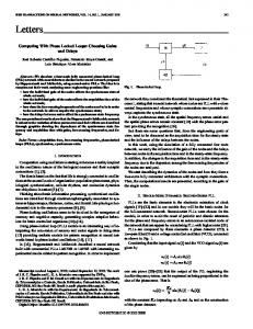
Fig. 2. Software architecture of RoboTwin.
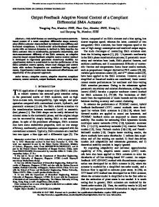
backlash between joints, unexpected disturbances in signal measurements, difficulty in parameter adjustment and other limitations. Among the large amount of control schemes appeared in the literature, only a small set of them has been verified by real experiments. Moreover, to the best of our knowledge, so far no satisfactory experimental results have been reported in the literature on NN-based stable closed-loop robotic control. Thus, in order to verify the effectiveness of the NN controller proposed in previous sections, extensive experimental tests have been conducted with a real manipulator arm. The experiments were carried out on the IRIS facility RoboTwin (Fig. 1), which is a modular and reconfigurable robot [15]. RoboTwin is a dual arm that comprises at least two robotic manipulators, each having several modular rotary joints. Each joint is driven by a dc brushless motor connected to the output link through a harmonic drive gear, and is instrumented with both position and torque sensors. Fig. 2 illustrates the software architecture of the RoboTwin experimental system. The real-time controller of the RoboTwin has also been designed to be modular and expandable. It is based on a nodal architecture with a PC-486 host and an AMD29050 coprocessor as the CPU
LIN AND GOLDENBERG: NEURAL-NETWORK CONTROL OF MOBILE MANIPULATORS
1129
TABLE I EXPERIMENTAL ROBOT PARAMETERS
TABLE II PERFORMANCE COMPARISON BETWEEN STC AND NNC
of each secondary node. Each node is capable of controlling eight joints at 1 KHZ while executing over 1000 FP (Float Point) operations per joint in each sampling interval. High digital and analog input–output (I/O) speed is achieved by the use of parallel I/O boards connected to the EISA bus [15]. In our experiments, we used one manipulator arm with four actuated joints. The dynamics parameters of the arm were assumed to be completely unknown. The joint positions were measured using high precision position sensors. The joint velocities were estimated using simple numerical position differentiation, which caused significant estimation errors, and therefore, affected the control performance. Such a four-joint robotic system presents a nonlinear and tightly coupled dynamics, making its control a challenging issue [15]. In addition, friction and backlash present in the joints were found to have a significant influence on the tracking performance, and also greatly substantiated the difficulty of control design. Three groups of experiments were performed: 1) a well-tuned PID controller; 2) a saturation-type robust controller (STC) [12] (i.e., PID plus a STC compensation portion); and 3) the proposed NN controller (NNC) (i.e., PID plus an NNC compensation portion), respectively. All three controllers were designed to have the same PID portion; therefore, the experimental results directly show the effect of STC and NNC. It was shown in the experiments that the STC achieved a slightly better performance in comparison with PID. Thus, only the results of STC and NNC will be presented in the following for the consideration of saving space. The structure of STC is defined by the following [12]: (80) where position error; differential gain; proportional gain; if if (81)
TABLE III PERCENTAGE IMPROVEMENT IN PERFORMANCE OF NNC OVER STC
where the parameters and are positive scalars that must be determined uniquely for each specific robot arm. In Lewis et al. [12], it was proven that the control law given by (80) and (81) guarantees the uniform ultimate boundedness of the closed-loop tracking errors. However, in the experiments, the stability of the closed-loop system was found to be highly sensitive to all these parameters: a small variation in any of them caused instability, e.g., arm-shaking. No such pathological phenomena were observed in the experiments when the proposed NNC and RDC controller were used. However, due to the inaccuracy of estimated velocity signals by using position measurement differentiation, high-frequency noise was introduced into the control loop as shown in the figures below. Table I presents the experimental robot parameters for the PID and STC. The parameters of the STC controller were initially designed based on the dynamic property of RoboTwin, then they were tuned for improved performance from extensive experiments. The parameters were found to be highly sensitive to the stability of the closed-loop system, making their tuning very difficult. The derivative gains of the PID control portion were chosen small in order to degrade the significant influence of estimation errors in the velocity signals, which was due to the inaccuracy of numerical differentiation procedure. A RBF network was constructed, with 20 input neurons, 80 hidden layers, and four output neurons, to estimate on-line the unknown nonlinear dynamics (57). Gaussian functions defined in (64) were chosen as RBF basis functions. For simplicity, all RBF functions have fixed centers, with widths set as [ 5, 5] that are in accordance with the ranges of the driving torques of all
1130
IEEE TRANSACTIONS ON NEURAL NETWORKS, VOL. 12, NO. 5, SEPTEMBER 2001
Fig. 3. Desired trajectories.
Fig. 4. Position errors of joint 1 and joint 2 (left column: STC; right column: NNC).
LIN AND GOLDENBERG: NEURAL-NETWORK CONTROL OF MOBILE MANIPULATORS
Fig. 5. Position errors of joint 3 and joint 4 (left column: STC; right column: NNC).
Fig. 6. Driving torques of joint 1 and joint 2 (left column: STC; right column: NNC).
1131
1132
IEEE TRANSACTIONS ON NEURAL NETWORKS, VOL. 12, NO. 5, SEPTEMBER 2001
Fig. 7. Driving torques of joint 3 and joint 4 (left column: STC; right column: NNC).
joints. The input pattern of the NN controller was chosen as . The coupled dynamics transmitted from the vehicle base in (57) were absent because of the fixed-base of RoboTwin. The outputs of the RBF net represent the compensation torques for nonlinear dynamics of all joints. The weights of the RBF net were simply initialized at zero and were updated timely at each control cycle using the proposed learning law (67) with the system sampling frequency set at 500 Hz, and the learning rate of the RBF net chosen as 0.35. Table II shows the comparison of error measurements between STC and NNC. Table III gives the percentage improvements of the sum of the square errors for each joint provided by NNC over STC, which proves that NNC is much more robust than STC. The figures also show that the tracking performance is improved over time by using NNC, which verifies its strong learning capability. The comparison illustrates that NNC works significantly better than STC, and verifies its effectiveness. Fig. 3 shows the desired sinusoidal trajectories to be tracked by the four joints. Figs. 4 and 5 present the position errors of each joint by using STC (left column) and NNC (right column), respectively. Fig. 6 and Fig. 7 are the driving torques provided by the STC (left column) and NNC (right column). Due to the inaccuracy of estimated velocity signals by using numerical position differentiation, significant high-frequency noise is introduced into the control loop as observed from the figures, which affects the tracking performance significantly. The experimental results show that, by using NNC the magnitudes of both maximum positive and negative tracking errors of all joints are smaller than those of STC, and the sum of squared
errors decrease by about 30–60% (Table III), which is very significant. The results also show that the tracking performance is improved over time, which illustrates the learning capability of the proposed NN controller, while STC does not provide such capability. VI. CONCLUSION In this paper, a NN-based methodology was developed for the joint space position control of a mobile manipulator with unknown dynamics and disturbances. Two NN controllers were proposed to control the vehicle and manipulator independently, each taking into account the dynamics couplings. Each NN controller output comprises a linear control term (i.e., classical PID control) and an NN compensation term. The NN compensation terms are used for on-line estimation of unknown nonlinear dynamics caused by unknown dynamics. No preliminary learning stage is required for the NN weights. The control scheme has the adaptation and learning capabilities, and is capable of disturbance-rejection in the presence of unknown and bounded disturbances. New NN on-line weight-updating laws were derived. The closed-loop stability, convergence of the learning processes and boundedness of the NN estimation weights were all rigorously proven. Experiments conducted on a real robotic manipulator illustrated the effectiveness of the proposed theory. REFERENCES [1] N. Hootsmanns and S. Dubowsky, “The motion control of manipulators on mobile vehicles,” in Proc. IEEE Conf. Robot. Automat., 1991, pp. 2336–2341.
LIN AND GOLDENBERG: NEURAL-NETWORK CONTROL OF MOBILE MANIPULATORS
[2] Y. Yamamoto, “Modeling and control of mobile manipulators,” Ph.D. dissertation, Univ. Michigan, Ann Arbor, 1994. [3] K. Liu and F. L. Lewis, “Decentralized continuous robust controller for mobile robots,” in Proc. IEEE Conf. Robot. Automat., 1990, pp. 1822–1827. [4] O. Khatib et al., “Vehicle/arm coordination and multiple mobile manipulator decentralized cooperation,” in Proc. IEEE/RSJ Conf. Intell. Robot. Syst., vol. 3, 1996. [5] K. Tahboub, “Observer-based control for manipulators with moving bases,” in Proc. IEEE/RSJ Int. Conf. Intell. Robo. Syst., 1997, pp. 1279–1284. [6] J. Chung, S. Velinsky, and R. Hess, “Interaction control of a redundant mobile manipulator,” Int. J. Robot. Res., vol. 17, no. 12, pp. 1302–1309, 1998. [7] F. L. Lewis, S. Jagannathan, and A. Yesildirek, Neural Network Control of Robot Manipulators and Nonlinear Systems. London, U.K.: Taylor and Francis, 1999. [8] M. Polycarpou, “On-line approximators for nonlinear system identification: A unified approach,” in Neural Network Syst. Techniques Applicat., X. Lenodes, Ed., 1998, vol. 7, pp. 127–155. [9] Y. Jin et al., “Stable manipulator trajectory control using neural networks,” in Neural Systems for Robotics, X. Omid et al., Ed. New York: Academic, 1997, pp. 117–151. [10] D. Gorinevsky, A. Kapitanovsky, and A. A. Goldenberg, “Network architecture and controller design for automated car parking,” IEEE Trans. Contr. Syst. Technol., vol. 4, pp. 50–56, 1997. [11] R. Fierro and F. L. Lewis, “Control of a nonholonomic mobile robot using neural networks,” Proc. IEEE Trans. Robot. Automat., vol. 9, pp. 589–600, 1998. [12] F. Lewis et al., Control of Robot Manipulators. New York: Macmillan, 1993. [13] I. Kolmanovsky and N. McClamroch, “Developments in nonholonomic control problems,” IEEE Contr. Syst., pp. 20–36, 1995. [14] Y. Kanayama, Y. Kimura, F. Miyazaki, and T. Noguchi, “A stable tracking control method for an autonomous mobile robot,” in Proc. IEEE Conf. Robot. Automat., vol. 1, 1990, pp. 384–389. [15] R. Hui, N. Kircanski, A. A. Goldenberg, C. Zhou, and P. Kuzan, “Design of the IRIS facility—A modular, reconfigurable and expandable robot test bed,” in Proc. IEEE Conf. Robot. Automat., vol. 3, 1993, pp. 155–160. [16] Y. F. Zhang, Recent Trends in Mobile Robots. Singapore: World Scientific, 1993. [17] A. M. Bloch, M. Reyhanoglu, and N. H. McClamroch, “Control and stabilization of nonholonomic dynamic systems,” IEEE Trans. Automat. Contr., vol. 37, pp. 1746–1757, 1992. [18] W. E. Dixon, D. M. Dawson, E. Zergeroglu, and F. Zhang, “Robust tracking and regulation control for mobile robots,” Int. J. Robust Nonlinear Contr., vol. 10, pp. 199–216, 2000. [19] S. S. Ge, T. H. Lee, and C. J. Harris, Adaptive Neural Network Control of Robotic Manipulators. Singapore: World Scientific, 1998. [20] R. M. Sanner and J.-J. E. Slotine, “Stable adaptive control and recursive identification using radial Gaussian networks,” in Proc. IEEE Conf. Decision Contr., Brighton, U.K., 1991.
1133
Sheng Lin was born in 1972 in Fujian Province, P. R. China. He received the B.Sc. degree in communication engineering from Beijing Information Technology Institute, Beijing, China, in 1992 and the M.A.Sc. degree in automatic control engineering from Beijing University of Aeronautics and Astronautics in 1995. In 1995 and 1996, he was with Shanghai Aircraft Research Institute, Shanghai, China, where he worked mainly on analysis and design of real-time flight control systems, real-time simulation and image generation. In 1997, he joined China Autosoft Company, Beijing, where he was involved in design of real-time embedded systems. Since September 1997, he has been a Graduate and Research Assistant in the Robotics and Automation Laboratory, Department of Mechanical and Industrial Engineering, University of Toronto, Toronto, ON, Canada. His current research interests include mobile robots, neural networks, intelligent control, robust control, real-time control, and embedded systems.
A. A. Goldenberg (S’73–M’76–SM’87–F’96) received the B.A.Sc. and M.A.Sc. degrees from the Technion—Israel Institute of Technology, Haifa, Israel, in 1969 and 1972, respectively, and the Ph.D. degree from the University of Toronto, Toronto, ON, Canada, in 1976, all in electrical engineering. From 1975 to 1981, he was employed by Spar Aerospace Ltd., Toronto, where he worked mainly on control, analysis, design of the space shuttle remote manipulator system and satellite controls. During 1981 to 1982, he was an Assistant Professor of Electrical Engineering and from 1982 to 1987, he was an Associate Professor of Mechanical Engineering at the University of Toronto. Since 1987, he has been a Professor of Mechanical Engineering at the University of Toronto. He holds cross appointments in the Department of Electrical Engineering and the Institute of Biomedical Engineering. He has founded the Robotics and Automation Laboratory in 1982 and the Mechatronics Laboratory in 1996 at the University of Toronto. His current research interests are in the field of robotics and industrial automation, with emphasis on biotechnology, medical applications and robotics in hazardous environments. He has published extensively in the academic and trade literature. He is the Founder and President of Engineering Services, Inc. (ESI) (www.esit.com), a high-technology company involved in the development of prototype robotic-based automation, and products. Currently, he is also the President of Virtek Engineering Sciences Inc. (VESI) a wholly-owned subsidiary of Virtek Vision International Inc. (TSE: VRK). VESI is involved in automation for biotechnology. Dr. Goldenberg is a former Editor of the IEEE TRANSACTION ON ROBOTICS AND AUTOMATION. He is a member of the American Society of Mechanical Engineers and the Professional Engineers of Ontario.