We propose a hardware architecture which which takes advantage of high parallelism .... and converted to a serie of digital data. These data are ... images and make a decision according to the particle signature depicted on the images from ...
ESANN'2008 proceedings, European Symposium on Artificial Neural Networks - Advances in Computational Intelligence and Learning Bruges (Belgium), 23-25 April 2008, d-side publi., ISBN 2-930307-08-0.
Neural Network Hardware Architecture for Pattern Recognition in the HESS2 Project Narayanan Ramanan1 , Sonia Khatchadourian2 , Jean-Christophe Pr´evotet2 and Lounis Kessal2 1- IIT Madras- Dept. of Electrical Engineering Chennai-600036 - India 2- ETIS Laboratory - CNRS UMR 8051 - ENSEA - University of Cergy-Pontoise 6 Avenue du Ponceau, 95014 Cergy-Pontoise - France Abstract. In this paper, we consider the problem of implementation of neural network in the context of the level 2 trigger of HESS2 project. We propose a hardware architecture which which takes advantage of high parallelism, pipelining and the intrinsic nature of FPGAs.
1
Introduction
Neural networks have successfully been implemented in a wide variety of applications and keep on demonstrating their efficiency compared to other classical techniques in pattern recognition and classification. One interesting field in which neural techniques have been of a great interest is the triggering of particles in physics experiments [1],[2] . The triggering specificity consists (i) in taking a decision according to collected events and (ii) in identifying the nature of particles issued from an impact within a collider. These experiences have clearly taken advantage of the neural approach in terms of performances and accuracy. In this article, a solution based on a neural system is proposed in a close domain: the gamma-ray astronomy. The presented results have been developed within the HESS collaboration which is interested in detecting cosmic gamma ray sources all around the universe. The HESS1 experiment [3] is based on the atmospheric Cherenkov technique: as a high energy cosmic ray hits the atmosphere, it creates an extensive air shower by interaction with the atmosphere. This phenomenon is known as Cherenkov light. The experiment consists in studying this Cherenkov light in order to detect the gamma particles hitting the atmosphere. It thus permits to evaluate the position and nature of the gamma-ray sources. The current HESS1 system (phase 1) is composed of four imaging Cherenkov telescopes, arranged on a square. By combining the information of, at least, two telescopes at the same time, the system makes intensive use of the stereoscopic approach. This enables to significantly increase the performances in terms of high energy particle detection (from 100GeV to 50TeV). One of the main specificities of these experiences resides in its capability of processing huge amount of data in a restricted time window. A trigger system composed of two levels has been designed within the HESS1 experiment: a level 1 (L1) per telescope and a unique central trigger. Such a trigger system is useful to make an on-line selection of relevant events for further off-line processing.
343
ESANN'2008 proceedings, European Symposium on Artificial Neural Networks - Advances in Computational Intelligence and Learning Bruges (Belgium), 23-25 April 2008, d-side publi., ISBN 2-930307-08-0.
The trigger inputs coming from the telescope consist of a 960-pixel image. An image represents a particle signature. The L1 trigger consists in removing isolated pixels within the collected image by applying analog thresholds. These pixels are typically due to noise and do not bring any additional information on the particle type. A global central trigger allows to perform time correlation between relevant data sent by each L1. If there are relevant data from at least two telescopes at the same time, the event is stored for future off-line image analysis and source reconstruction.
2
The HESS2 project
The outstanding performance obtained so far in the HESS1 experiment has led the research labs involved in this project to improve the existing system [4]. A Very Large Cherenkov telescope (VLCT) is currently being built and will take place in the center of the previous telescope system. The VLCT will reduce the energy threshold in stereoscopic mode allowing to collect more photons at a given energy. It will function in monoscopic mode for lower energies. Moreover, the VLCT camera will also be improved. All these improvements will contribute to a better sensitivity of the HESS1 system. The quality and the reconstruction of the gamma parameters will thus be improved. The HESS2 experiment will upgrade the HESS1 experiment by (i) featuring a new event class (energies from 10 to 50GeV), (ii) increasing the previous system sensitivity for energies from 50 to 100GeV, (iii) improving the resolution for energies upper than 100GeV. Moreover, in order to increase the sensitivity and thus obtain the best performances, the trigger threshold will be reduced. In this context, the quantity of data to be collected by the VCLT will drastically increase. A simulated trigger rate of 2.5kHz is expected, reaching up to 20kHz for the trigger worst conditions. The trigger rate associated with the huge amount of data to be processed on line (240GBauds in approximately 10µs) has led the collaboration to propose a new efficient trigger scheme composed of three levels: two trigger levels (L1 and L2) and a central trigger.
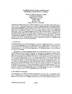
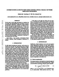
Fig. 1: Trigger system in HESS2 The Fig. 1 describes the function of the trigger system. Data coming from the camera are stored in the SAM (Swift Analog Memory) allowing the storage of an entire image. In parallel, data are also sent to the level 1 trigger (L1)
344
ESANN'2008 proceedings, European Symposium on Artificial Neural Networks - Advances in Computational Intelligence and Learning Bruges (Belgium), 23-25 April 2008, d-side publi., ISBN 2-930307-08-0.
which has the same structure as in HESS1. The L1 trigger notably generates a binary signal indicating whether a specific event has to be kept (L1Accept) or rejected (L1Reject). If the L1Accept signal is valid, the complete image is stored and converted to a serie of digital data. These data are stored in a FIFO until a L2Accept/L2Reject signal coming from the level 2 trigger (L2) which will decide to keep or reject this event. In parallel, data are sent to the PreL2 stage which thresholds the incoming images according to three energy levels. The image are then sent to the L2 trigger. The L1 and L2 decisions are expected at average rates of 100kHz and 3.5kHz respectively.
3
The L2 Triggering problem
The structure of the L2 trigger receives L1Accept signals from the trigger management system at a maximum rate of 100kHz and must deliver a decision at a 3.5KHz rate. Incoming data consist of 2048 pixels that are threshold by the PreL2 step. Moreover, each pixel of the image can only take three different values according to their energy levels. The L2 trigger is meant to rebuild the images and make a decision according to the particle signature depicted on the images from the PreL2. A signature can represent 3 different types of particles: gammas, protons or muons. In order to solve this pattern recognition problem, a neural solution associated to its preprocessing steps has been envisaged.
4
A Neural solution
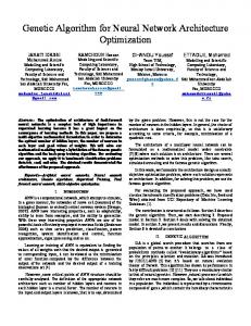
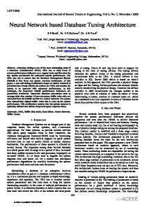
The L2 trigger can be divided in 3 steps as shown in Fig. 2: a rejection step, a preprocessing step and a classifier. Since a particle signature has to be processed by the L2 trigger in 10µs (PreL2 feed the L2 at a rate of 100kHz), and according to processing latencies, the rejection and preprocessing steps assumed to be processed in about 5µs. This only leaves 5µs to perform the classification.
Fig. 2: Level 2 trigger system The rejection step permits to eliminate very small particles whose signature is smaller than 4 pixels. In such case, it is assumed that the classifier is not able to make a valuable decision. The preprocessing step consists in applying more or less complex transformations on the images. This aims at reducing the input space of the classifier in order to drastically simplify the learning process. Many preprocessing algorithms have been envisaged and most of them are destined to apply transformations on the images in order to help the classifier in its task.
345
ESANN'2008 proceedings, European Symposium on Artificial Neural Networks - Advances in Computational Intelligence and Learning Bruges (Belgium), 23-25 April 2008, d-side publi., ISBN 2-930307-08-0.
Such transformations deal with rotation and translation invariance of the particle signature within the image. The extraction of region of interest [5], Zernike [6] and Hu moments [7] have been notably studied and provide satisfactory results in terms of recognition performances. The proposed classifier is a MLP neural network with a single hidden layer and 3 outputs corresponding to the different classes of particles to be determined (gammas, muons, protons). The number of inputs depends on the preprocessing step and it is assumed to get a value between 6 and 50 at a maximum.
5
Proposed Neural Network Architecture
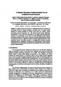
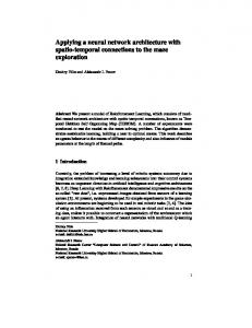
According to the nature of the various preprocessing algorithms, it has been envisaged to design a flexible architecture that may easily adapt to a new configuration of the neural network architecture. The architecture enables to process a multi-layer perceptron composed of I input nodes, H hidden nodes and O output nodes. An example of the proposed architecture for I = 6, H = 8, O = 3 is depicted in Fig. 3. Incoming data arrive in sets A, B,etc. where each set contains I elements. The architecture is divided into two levels : the Hidden layer Computation (HC) and the Output layer Computation (OC).
Fig. 3: Neural network with 6 inputs, 8 hidden units and 3 outputs. Each input arrives at each clock cycle and is maintained for H clock cycles. Any j th ROM in HC, stores all the weights corresponding to the j th input node, connected to H hidden nodes (i.e. wjk where k runs from 1 to H), shifted in order by j − 1. Any ith ROM in OC stores the weights corresponding to all the interconnections of that output node with all the nodes of the hidden layer (i.e. wki where k runs from 1 to H). The output of the counters are used to select the appropriate weights to be passed on to the corresponding multipliers.
346
ESANN'2008 proceedings, European Symposium on Artificial Neural Networks - Advances in Computational Intelligence and Learning Bruges (Belgium), 23-25 April 2008, d-side publi., ISBN 2-930307-08-0.
At each clock cycle, at the j th level in HC, apart from the addition operation between the present multiplier output and the partial sum from the previous level, the multiplication operation for the next input is also simultaneously performed. Thus, at each clock cycle, the sum ripples and accumulates through HC adders until SIGMOID0 is fed. This block feeds the outputs of the hidden layer sequentially to all the multiply-accumulators (MACs) in OC which produce the weight-input inner product for each output node after receiving all the outputs of the hidden layer. Each adder, multiplier and activation function unit (sigmoid) has a latency of 1 clock cycle. The final results of the output layer in OC are available in parallel as o1, o2, o3 from the corresponding sigmoid blocks. In general, the neural network outputs are available I +H +c clock cycles after the first input of a set is given, where c is a constant depending on the latencies of different blocks in the system. In the example illustrated above, since the latency of the MAC unit is 4, c = 6. The outputs are available H + d clock cycles after the arrival of the last input of the set, where d is also a constant depending on the latencies of different blocks in the system. In the above example, d = 7. On each clock cycle, I + O multiplications corresponding to I + O multiplying units are done, which implies computing rate of (I + O) ∗ f CPS. 5.1
Advantages of the architecture
The number of multipliers required for the network is fixed to I + O, independent of any arbitrarily large number of hidden nodes. A single activation function unit (sigmoid) is used for the entire hidden layer. This enables to save memory resources available within the FPGA. This architecture is also highly pipelined. Since the architecture does not require complex control, scalability to accommodate more hidden, input or output nodes is ensured. 5.2
Simulation Results
The architecture was implemented on a Xilinx Virtex 4 xc4vfx12 FPGA which is one of the smallest device of the family. This circuit has been envisaged since it should be retained in the HESS2 project. The activation function sgn(x) ∗ (1 − 2−|x| ) [8] has been used. This function is similar to the sigmoid function and is easy to implement on hardware with shift registers and adders. The resources consumed by this implementation vary insignificantly with the precision of x, as compared to that consumed by a pure look up table based implementation. Moreover, memory must be saved in our context, since the preprocessing phase should make intensive use of LUTs. The inputs and weights are implemented with 16 bits precision due to the nature of the preprocessed incoming data. The ROMs are 256 words deep. The multipliers are implemented with embedded DSP48s blocks. The synthesis report of different neural networks configurations is summarized in table 1. The implementation report shows that the required resources do not vary significantly according to a given number of hidden nodes. Only the processing time changes. Note that the timing constraints are respected by
347
ESANN'2008 proceedings, European Symposium on Artificial Neural Networks - Advances in Computational Intelligence and Learning Bruges (Belgium), 23-25 April 2008, d-side publi., ISBN 2-930307-08-0.
far and that a more ambitious and time-consuming preprocessing stage may be envisaged within the same chip. Neural network configuration I, H, O 6, 12, 3 6, 8, 3 6, 16, 3 25, 50, 3 25, 35, 3 25, 65, 3
Maximum frequency (MHz) 118.43 118.43 118.43 118.43 118.43 118.43
Occupied slices 2034 2035 2034 5228 5229 5230
(37%) (37%) (37%) (95%) (95%) (95%)
4 input LUTs 3715 3717 3715 9272 9273 9275
(33%) (33%) (33%) (84%) (84%) (84%)
DSP48s
9 (28%) 9 (28%) 9 (28%) 28 (87%) 28 (87%) 28 (87%)
Execution time (ns) 240 200 280 810 660 960
Table 1: Summary of implementation reports and execution times at a frequency of 100MHz for different configurations of neural networks
6
Conclusion
The proposed hardware architecture enables to process neural networks in realtime according to the tight timing constraints imposed by the HESS2 experiment. By combining high parallelism and pipelining and by taking advantage of the intrinsic nature of FPGAs, it allows efficient process of neural networks at a micro-second scale, opening a wide range of unexplored real-time applications.
References [1] B. Denby et al., Fast Triggering in High Energy Physics experiments using Neural Networks, IEEE Transactions on Neural Networks, 14:1010-1027, IEEE Computational Intelligence Society, 2003 [2] H. Gemmeke et al., Neural Network Chips for Trigger Purposes in High Energy Physics, Proceedings of Nuclear Science Symposium (NSS), 1996. [3] W. Hofmann, The H.E.S.S. Project, in R. Enomoto, M. Mori, S. Yanagita, editors, proceedings of Symposium The Universe Viewed in Gamma-Rays, Universal Academy Press,Inc, pages 357-363, September 25-28, Kashiwa (Japan), 2002. [4] P. Vincent for the H.E.S.S. collaboration, H.E.S.S. Phase II, Proceedings of the 29th International Cosmic Ray Conference (ICRC 2005), Tata Institute of Fundamental Research, pages 163-166, August 03-10, Pune (India), 2005. [5] S. Khatchadourian, J.-C. Pr´evotet and L. Kessal, A Neural Solution for the Level 2 Trigger in Gamma Ray Astronomy, Proceedings of the 11th Advanced Computing and Analysis Techniques in Physics Research (ACAT 2007), Proceedings of Science, April 23-27, Amsterdam (Netherlands), 2007. [6] R. Mukundan and K.R. Ramakrishnan, Moment functions in image analysis: theory and applications, World Scientific, Singapore, 1998. [7] M.K. Hu, Visual Pattern Recognition by Moment Invariants, IRE Trans. Information Theory, 8:179-187, 1962. [8] M. Skrbek, Fast Neural Network Implementation, Neural Network World, 9:375-391, ICS, 1999.
348