The International Archives of the Photogrammetry, Remote Sensing and Spatial Information Sciences, Volume XLI-B8, 2016 XXIII ISPRS Congress, 12–19 July 2016, Prague, Czech Republic
NEW APPROACH FOR SEGMENTATION AND EXTRACTION OF SINGLE TREE FROM POINT CLOUDS DATA AND AERIAL IMAGES A. S. Homainejad Independent Research Group on Geospatial, Tehran, I.R. Iran
[email protected] Commission THS10 KEY WORDS: Segmentation, Boundary Lines, 3D Model, Biomass, Single Tree ABSTRACT: This paper addresses a new approach for reconstructing a 3D model from single trees via Airborne Laser Scanners (ALS) data and aerial images. The approach detects and extracts single tree from ALS data and aerial images. The existing approaches are able to provide bulk segmentation from a group of trees; however, some methods focused on detection and extraction of a particular tree from ALS and images. Segmentation of a single tree within a group of trees is mostly a mission impossible since the detection of boundary lines between the trees is a tedious job and basically it is not feasible. In this approach an experimental formula based on the height of the trees was developed and applied in order to define the boundary lines between the trees. As a result, each single tree was segmented and extracted and later a 3D model was created. Extracted trees from this approach have a unique identification and attribute. The output has application in various fields of science and engineering such as forestry, urban planning, and agriculture. For example in forestry, the result can be used for study in ecologically diverse, biodiversity and ecosystem.
1. INTRODUCTION With emerging new techniques in both imagery and image processing, there is an opportunity for generating a comprehensive and precise 3D model from objects and surfaces. This opportunity has been overwhelmingly appreciated by a wide range of users, but it couldn’t satisfy all requests for an ultimate 3D model. 3D modelling is reaching its mainstream popularity in these days; however, users are seeking for a 3D model that is able to precisely show all details from the objects. An ultimate 3D model comprises the following characteristics such as more realistic, exposing boundary clearly, flexibility, and precision. Photogrammetry is a technique for acquiring 3D data from objects for years. The techniques of image acquiring in photogrammetry are classified in two major groups of active and passive imageries. Since last decade, laser scanners are effectively using for acquiring 3D data from objects, surfaces, and terrains; consequently, these data are being used for reconstructing accurate Digital Elevation Models (DEM), or Digital Surface Models (DSM), or Digital Terrain Models (DTM). Usually, most studies in laser scanners data are focusing on deriving DSM or DEM from point cloud for analysing the topographic characters of the terrain and the surface (Lee and Younan 2003, Brzank et al. 2008). Laser scanners data have had great benefits for users that include rapid and simple process, providing precise details from indoor and outdoor objects, plus revolutionary cost effective. As a result, laser scanners have been utilised for multiple purposes and application. For example in forestry, laser scanners have had applications for ecological assessment, forest operation management, and geomorphology (Pirotti et al. 2008) and one of the applications in forestry is detecting and extracting trees. The segmentation of trees from point clouds data has been explained in various literatures (Lin and Hyyppa 2016, Casas et al. 2016, Homainejad 2013, Homainejad 2012, Secora 2007, Li et al. 2012, and Lindberg et al. 2013). Basically, the segmentation of a single tree between groups of trees is a tedious and almost impossible job, but it is very important in forestry, urban planning, and agriculture. The purposes of single tree delineation have been explained in abundant literatures (Wolf and Helpke 2007, Krahwinkler and Rossmann 2013, and Engler et al. 2013). For example, study in ecosystem and
wildlife or precise measurements of biomass in forest are two main reasons for detecting and delineating of single trees (Lr Roux et al. 2015, Jakubowski et al. 2013). Usually, trees come with different shapes and sizes that it might disturb the process of the segmentation and delineation. Therefore, some studies (Jakubowski et al. 2013, Malthus and Younger 2000, and Brandtberg 2007) have been focused on segmentation of a particular type of tree, or some studies focused on cluster tree classification from airborne images using unsupervised classification approach (Schäfer et al. 2016), or some studies focused on single tree extraction from ALS data using Canopy Height Model (CHM) or normalised CHM (Zhamg et al. 2014, and Mongus and Zalik 2015). This paper discusses a new approach for delineation and extraction of individual trees from point cloud data and aerial image for reconstruction a 3D model. The approach has been successfully tested and implemented on a number of data. The final output is a 3D model from the trees that it includes coordinates and specie’s attributes, which can be used in various studies. This paper is organised into six sections. An overview on laser scanner data is given in the next section. Section 3 discusses the proposal. The study area is given in the section 4. Section 5 discusses the experiments and results followed with the conclusion. 2. A BRIEF OVERVIEW ON AIRBORNE LASER SCANNERS The technical information relating to airborne laser scanners has been widely covered in abundant literatures such as (Wehr and Lohr 1999, Kirchhof 2008, and Petrie 2011), and there is no requirement to go in details here. Since the segmentation of the single tree from point cloud data is the key research in this project, the Airborne Laser Scanners (ALS) technology and its behaviour in vegetation canopy are briefly reviewed. An ALS consists of two parts of the hardware and the software. The hardware is a laser rangefinder that fires laser pulses in short or long wavelengths. The wavelengths which are employed in ALSs vary in size and type such as Near Infra-Red (NIR) which has been employed in early versions of ALSs, Short Wavelength Infra-Red (SWIR), and blue-green part of
This contribution has been peer-reviewed. doi:10.5194/isprsarchives-XLI-B8-1287-2016
1287
The International Archives of the Photogrammetry, Remote Sensing and Spatial Information Sciences, Volume XLI-B8, 2016 XXIII ISPRS Congress, 12–19 July 2016, Prague, Czech Republic
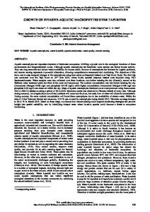
spectrum. A GPS and an IMU are always on board for continuously positioning the ALS unit during scanning operation. Plus GPS and IMU, a precise clock is using on board for measuring the precise time for calculation the distance between the laser scanner and the object as illustrated in equation 1. The footprints of the laser scanners are varying from 0.2 meter to 2.0 meter and the receiver’s field-of-view is varying from 0.2 meter to 5.0 meter. Finally, the returned echo from object accompany with all other acquired data (pulse travelling time, GPS and IMU data) are digitised and transferred to an on board computer for post processing. dist = (t(two ways)/2)*c (1) Where: dist is the distance between the laser scanner and object, t is the travelling time, and c is the speed of light. The earlier version of ALSs transmitted pulses within a defined time intervals. Their technology was designed based on lapse of time between firing pulses and receiving the echo. The elapsed time was calculated based on the flight altitude and accuracy of mapping. In the new version of ALSs, the elapsed time has been eliminated by supplying new technology of recording multiple pulses simultaneously; consequently, the new ALSs continually is transmitting pulses and recording their returned echoes. The new technique of ALS varies in employing wavelengths, for example Leica Geosystems has used the technique of “MultiplePulses-in-the-air” (MPiA), or the technique of “Continuous Multi-Pulse” (CMP) is being used by Optech, or RIEGL is using “Multiple Time Around” (MTA) technique. The new versions of the laser scanners are able to receive multiple scattered echoes from a single pulse that is suitable for detecting and segmenting trees from point cloud data. Indeed, each pulse has more than one returned pulse from a tree. When a pulse hits a tree, it is scattered and a portion of pulse returns to the ALS and one part is penetrating and continuing its path. This process is continuing until the signal hits the ground and returns to the ALS. The new ALSs are able to record four returned scattered pulses of a single pulse; therefore, the new ALSs are able to give more details about the trees that can be used in better segmentation. The density of point cloud in a 1 m2 is pretty much related to flight height and the number of the pulses. Usually the density of 4 points per 1 m2 is estimated for a flat land while the flight altitude is 1000 meters above the ground. This density can be exceeded up to 10 points (Jung et al. 2011) to 25 points (Mund et al. 2015) per 1 m2 for a dense vegetation area. The accuracy of point cloud very much related to accuracy of measuring range, scan angle and positioning. The accuracy of range is decreasing with increasing the flying height. This accuracy is 5cm when flying height is equal to 500 meters, and is 10cm when flying height is 1000s meter and so on (Petrie 2011). The accuracy of positioning much related to the accuracy of GPS/IMU devices that is varying from 0.05 meter to 0.3 meter. 3. PROPOSAL The idea consists of the following steps. In the first step a group of trees from point cloud data are detected and extracted. In this step, an ad hoc search for trees is carried out, and then a segmentation approach is implemented for discriminating single trees from the group of trees. The equation 2 shows the mathematical model of the segmentation approach as it models the relationship between the height of the peak points and the depression point of two adjoined trees. The equation 2 has been basically developed based on trial and error and Figure 1 visualises the concept of the equation 2.
(2) Where, d is the distance between two trees, d1 is the distance between the taller trees to the depression point, h1 and h2 are the heights of the two trees, and e is a factor related to type of tree and it was assumed zero for this project because the type of tree was unknown.
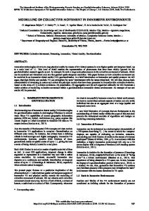
Figure 1. Two adjoined trees and a derived profile that are visualising the concept of the equation 2. The equation 2 calculates the depression point between two adjusted trees. The aim in this project is to detect the recorded depression point by ALS that is slightly different with the calculated one. The process of detection the recorded depression point consists the following steps: 1) calculate the location of depression point using the equation 2, 2) a search window is defined according to the calculated depression point for searching and extracting the depression points within the point cloud data, 3) the extracted points are registered onto the aerial image for assisting the object detection and extraction from the aerial image as the process was explained by Homainejad (2012), 4) finally, the extracted trees from the aerial image are converted to the point cloud data to be captured in a 3D space for creating and reconstructing a 3D model from the trees. 4. STUDY AREA Part of the city of Vaihingen in Germany has been chosen for this project (Figure2). The data and technical information from the area have been provided by ISPRS-Commission III. Also, the commission has provided a permit to researchers for using the technical data in their studies. The acquired aerial images and ALS data have been conducted by German Association of Photogrammetry and Remote Sensing (DGPF) Cramer (2010). The test area is a residential area includes multistorey buildings, and road infrastructure, and vegetable canopy. Two groups of aerial images and Laser Scanner Data were included with the source data. The aerial images were acquired by Intergraph Z/I DMC with 8 cm ground resolution and 11 bits radiometric resolution at 24 July and 6 August 2008. The images were stored in 16 bits RGB TIFF formats and their technical information includes the parameters of orientations can be achieved in ISPRS web site. The ALS data has been acquired on 21 August 2008 using a Leica ALS50 system with 45o field of view and mean flying height 500 m above ground. The average overlap strip is 30% with the median point density of 6.7 per meter and the mean point density for each strip is 4 point per meter.
This contribution has been peer-reviewed. doi:10.5194/isprsarchives-XLI-B8-1287-2016
1288
The International Archives of the Photogrammetry, Remote Sensing and Spatial Information Sciences, Volume XLI-B8, 2016 XXIII ISPRS Congress, 12–19 July 2016, Prague, Czech Republic
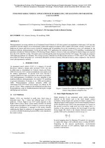
1 m2 for vegetation area. The criterion for points’ height inside the search window is illustrated in the following non-equations: GET, where GE is the ground level height, e is the height of a reference point in the search window, ei is height of point “i” in the search window, and T is a defined threshold. Then an algorithm was implemented to carry out the equation 2 within the search window in order to define the depression point and the boundary line between the adjoined trees. For assessing the result a TIN algorithm followed with contour lines was carried out on the output. The contour lines can provide the location of depression point and peak points, and a profile between the points in order to assess the obtained depression points from Equation 2 and the points on the depression line. A number of trials were carried out and their results were evaluated and analysed. Their results were illustrated in Figure 4. Figure 4 is illustrating the profile of trees that include two depression points; one has been obtained using the equation 2 and another is extracted from point cloud data. The investigation shows that the margin of two depression points, is in the range of “0.05*d1” along line of p1p2 and “0.2*d1” along depression line. Therefore, it can be concluded that the equation 2 did successfully define the location of the depression points on the ALS data with maximum 5% margin alongside of p1p2 line. In the study area some trees have multiple trunks as illustrated in Figure 5; therefore, the tree has multiple peaks point that its profile is demonstrating in Figure 6. In this situation, each small part was detected and extracted as a single tree and later they combined and captured as a single tree.
Figure 2. The area studies were highlighted on the aerial image. 5. EXPERIMENTS AND RESULTS 5.1 Field Experiments Initially a field experiment has been conducted in a divers and dens area (Figure 3) for testing and verifying the equation 2. The heights and distances of adjoined trees using surveying method were acquired and then the acquired data were inserted in the equation 2 for obtaining the boundaries between the crowns of two neighbouring trees. The obtained boundary was compared with the acquired data from the field work and the result has been presented in Table 1. The result indicated that the equation 2 can be trustfully used for defining the boundaries between crowns of two neighbouring trees.
HEIGHT
DBH
TREE1
30.5
0.906
TREE2
19.5
0.736
TREE1
26.5
0.999
TREE2
19.5
0.736
TREE1
5.631
0.25
TREE2
5.13
0.25
DISTANCE
d1
e
13.157
8.026
-d1*5%
6.506
3.748
+d1*45%
2.09
1.09
d1*0.06%
Table 1: The result from field experiment.
5.2 Detection and Extraction Trees from ALS Data In this step all trees on the selected area (Figure 2) were detected and extracted from point cloud data and captured in a 3D space for generating and reconstructing an initial 3D model from trees and later the 3D model was used for creating the final 3D model that include other attributes and integrated colour and texture. In order to detect and extract trees from point cloud data, an algorithm according to an approach that was explained by Homainejad (2012), was developed and implemented on the ALS data. The algorithm is assessing the points’ density, heights, and the intensity value within a search window against defined criteria. The size of the search window was equal to the size of the ALS footprint which was 0.39 m on diameter. The criterion was four points per 1 m2 in all area and 6.7 points per
Figure 3: The selected area for field experiment.
Figure 4. Four profiles of adjoined trees. The red area is the gap between the calculated depression point and the extracted.
This contribution has been peer-reviewed. doi:10.5194/isprsarchives-XLI-B8-1287-2016
1289
The International Archives of the Photogrammetry, Remote Sensing and Spatial Information Sciences, Volume XLI-B8, 2016 XXIII ISPRS Congress, 12–19 July 2016, Prague, Czech Republic
few months and trees would be changed physically within this period. Therefore, always there is a miss match between the point cloud data and the aerial image and basically we cannot improve this error, even with the applying a good orientation. The provided parameters of orientation by ISPRS have been utilised for orientation between the ALS data and the aerial image. Unfortunately, there was a mismatch, and the quantity of the mismatch in some parts was very significant as much as 500 pixels in each X and Y direction on the image as illustrated in Figure 6 and Table 2. Consequently, it was required to obtain new parameters of orientation for the area of study. The result after applying new parameters, illustrates accuracy in range of few pixels which it satisfies the aspects of this project, and consequently the extracted points were successfully registered onto the image for distinguishing the boundaries between trees and assisting in detection and extraction trees from the image. Figures 7, 8, and 9 depict the output from registering point cloud data on the image that each tree was defined and their boundaries have been distinguished. As Figure 8 shows, the boundaries were defined very well despite overlapping in some parts and Figure 9 shows the boundaries on a multi trunk tree. Each part of a multi trunk tree can be separately extracted and later can be captured as a single tree. The overlapped area is less than 5%.
Figure 5. A multi trunk trees.
COLLINEAR METHOD
DLT METHOD
∆x (PIXEL)
∆y (PIXEL)
∆x (PIXEL)
∆y (PIXEL)
10040082
-0.5
-107.5
0.5
-107
10040083
0.5
-18.5
1.5
-10.5
IMAGE
Figure 6. A topographic view from the multi trunk trees. The contour lines clearly show multiple peak point. The detected and extracted single trees from ALS data are captured individually in a 3D space in order to creating an initial 3D model. One of the advantages of this method is to edit and update each tree separately without affecting other trees as well as to have a DSM from trees. Later, more details relating to each tree can be integrated in the 3D model for further analysing. The 3D model obtained in this step is only created from point cloud. Later, these data are used for assisting in detection and extraction trees from aerial digital image and creating final 3D model.
10040084
4.5
39
5
37.5
10050104
-21.5
-265.5
-20.5
-269.5
10050105
21.5
-297.5
21.5
-298.5
10050106
-109
-206
-107.5
-206
Table 2: Mismatch values in X and Y directions for digital images that have been obtained using two methods of DLT and Collinearity Equations only for area 1. The calculation has been carried out on based of an assumption that the point clouds data has no errors.
5.3 Detection and Extraction Trees from Aerial Images In this step, each extracted tree from ALS data are transformed and registered onto the aerial image for assisting the process of detection and extraction of trees from aerial image. Homainejad’s approach (2012) has been employed for transforming and registering points from ALS data to the image. Prior to process of transformation and registration, an orientation has been carried out to orient the ALS data with the aerial image. The initial question was in what accuracy the peak point from the point cloud has to be matched with its correspondence point on the aerial image. Technically, the peak point from point cloud does not match with its correspondence point in the aerial image because: a) the peak point from the point clouds is fairly related to range and scattered waves returned from one of the points on the top of the tree not from the highest point of the tree, and b) the tree is not a stationary object and the highest point is changing constantly due to either natural or human reasons. Basically it doesn’t mean the first scattered wave is coming from the highest point of the tree but it is coming from a top point on the tree. C) Always there is a lapsing time between the time of imagery and the time of ALS data acquisition, and sometimes this lapsing time is more than
Figure 7: The miss match after registration of extracted trees from point cloud data onto the aerial image.
This contribution has been peer-reviewed. doi:10.5194/isprsarchives-XLI-B8-1287-2016
1290
The International Archives of the Photogrammetry, Remote Sensing and Spatial Information Sciences, Volume XLI-B8, 2016 XXIII ISPRS Congress, 12–19 July 2016, Prague, Czech Republic
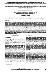
matches only with a point in the initial 3D model, and then it took the coordinates of that point. The points include the intensity values that inherited from the image. In the next step, each tree was individually captured in a 3D space as illustrated in Figure 11. Each tree was captured in an individual layout. The result is a new 3D model that can be used for different studies. Each single tree is impartial from other trees and has a unique identification; therefore, each tree can be updated and edited without effects on the other trees. Also, each tree can be assigned a number of attributes such as type and age tree.
Figure 8: The output from registration of the point cloud data on the image after applying the corrections.
Figure 11: The final 3D model that has been created from extracted trees from aerial images. 6. CONCLUSION
Figure 9: The extracted boundary of single trees.
Figure 10: The extracted boundary from a multi trunks tree. 5.4 Final 3D Model In this stage, the extracted trees from aerial image were converted from raster to vector and new point cloud was created. The image was transformed from pixel to point cloud by the method that was explained by Homainejad (2012), and then the new point cloud was captured in a 3D space to create the final 3D model. In the process of transformation, a set of coordinates (X, Y, Z) were bonded to the pixels. Each pixel
The main aspect of this project was to develop an approach that is able to detect and extract a single tree from ALS data and aerial image, and then create a 3D model from them. Homainejad’s approach for detection and extraction of trees from ALS data and the aerial images, and also for creation a 3D model was utilised. Since Homainejad’s approach has provided bulk segmentation from trees, a modification has been carried out in order to segment and extract single trees from ALS data and aerial images. The modification is reflected in the following steps. After the bulk segmentation from ALS data, A TIN and contour lines were carried out on the output. The contour lines can show the peak points and slope that they were used for defining the boundary lines and for segmentation and extraction of single trees. Then depression points were calculated using Equation 2. The depression points defined the boundary lines between trees. A search was carried out to detect the points alongside the depression line. Then each single tree was extracted and captured in a 3D space. After extracting trees from ALS data, the data was transformed and registered onto the aerial image for assisting the process of segmentation and extraction of its corresponding tree from the aerial image. Finally, the extracted trees from aerial image is transformed and registered onto the 3D space for creating a new 3D model. Each individual tree in the final 3D model can be independently updated, modified, and removed without affecting other trees and 3D model. Each tree has had a unique identification and attributes that includes the X, Y, Z coordinates plus the tree’s details such as type of tree, and age. Furthermore, each tree inherited intensity values from aerial image that can help to recognise the type of the tree. Since the 3D model is updateable, the 3D model can provide the latest details and information regarding to trees and environment.
This contribution has been peer-reviewed. doi:10.5194/isprsarchives-XLI-B8-1287-2016
1291
The International Archives of the Photogrammetry, Remote Sensing and Spatial Information Sciences, Volume XLI-B8, 2016 XXIII ISPRS Congress, 12–19 July 2016, Prague, Czech Republic
Therefore, the result from this approach has a great impact on other studies in environmental conservation and urban planning. For example, in forestry, the 3D model can be used for study in biomass and diversity, or in urban planning the 3D model can be used on the effects of pollution on trees. ACKNOWLEDGEMENTS Hereby, author would like sincerely to thank ISPRSCommission III and German Association of Photogrammetry and Remote Sensing for providing the source data and creating opportunely for researcher with giving permission to use data in their research. REFERENCES Brandtberg, T., (2007), “Classifying individual tree species under leaf-off and leaf-on conditions using airborne lidar”, Journal of Photogrammetry and Remote Sensing, 61, 325-340 Brzank, A., Heipke, C., Goepfert, J., Soergel, U., (2008), “Aspect of generation of digital terrain models in the Wadden sea from Lidar-water classification and structure line extraction”, Journal of Photogrammetry and Remote Sensing, 61, 510-528 Casas, A., García, M., Siegel, R.B., Koltunov, A., Ramírez, C., Ustin, S., (2016), Burned Forest characterization at single tree level with airborne laser scanning for assessing wildlife habitat, Remote Sensing of Environment Vol 175, 231-241 Cramer, M., (2010), “The DGPF test on digital aerial camera evaluation-overview and test design”, PhotogrammetrieFernerkundung-Geoinformation, 2, 73-82 Engler, R., Waser, L.T., Zimmermann, N., Schaub, M., Berdos, S., Ginzler, C., Psomas, A., (2013), Combining ensemble modelling and remote sensing for mapping individual tree species at height spatial resolution”, Forest Ecology and Management, 310, 64-73 Homainejad, A.S., 2013, A Mobile Mapping Approach for Disaster Management, Asian Journal of Environment and Disaster Management, Vol. 5, Issue 2, 177-190, 201 Homainejad, A.S., 2012, “An Innovation Approach for Developing a 3D Model by Registering a Mono Image on a DTM”, ISPRS Archives, Volume XXXIX-B4, 189-194 Jung, S.E., Kwak, D.A., Park, T., Lee, W.K., Yoo, S., (2011), “Estimating Crown Variables of Individual Trees using Airborne and Terrestrial Laser Scanners”, Remote Sensing Vol.3, 2346-2363 Kankare, V., Raty, M., Yu, X., Holopainen, M., Vastaranta, M., Kantola, T., Hyyppa, J., Hyyppa, H., Alho, P., Viitala, R., (2013), Single tree biomass modelling using airborne laser scanning, ISPRS Journal of Photogrammetry and Remote Sensing Vol 83, 66-73 Kirchhof, M., Jutzi, B., Stilla, U., (2008), “Iterative Processing of Laser Scanner Data by Full Waveform Analysis”, Journal of Photogrammetry and Remote Sensing, 63, 99-114 Krahwinkler, P., Rossmann, J., (2013), “Tree Species Classification and Input Data Evaluation”, European Journal of Remote Sensing, 535-549 Jakubowski, M.K., Li, W., Guo, Q., Kelly, M., (2013) “Delineating individual Trees from Lidar Data: A Comparison of Vector-and Raster-based Segmentation Approaches”, Remote Sensing www.mdpi.com/journal/remotesensing, 4163-4186 Le Roux, D.S., Ikin, K., Lindenmayer, D.B., Manning, A.D., Gibbons, P., (2015) “Single large or several small? Applying biogeographic principles to tree-level conservation and biodiversity offset”, Biological Conservation, Vol 191, 558-566
Lee, H.S., Younan, N.H., (2003), “DTM Extraction from Lidar Returns Via Adaptive Processing”, IEEE Transaction on Geoscience and Remote Sensing, Vol 41, No. 9, 2063-2069 Li, W., Guo, Q., Jakubowski, M.K., Kelly, M., (2012), “A New Method for Segmenting Individual Trees from the Lidar point Cloud”, Photogrammetric Engineering and Remote Sensing, Vol. 78, No. 1, 75-84 Lin, Y., Hyyppa, J., (2016), “A Comprehensive but efficient framework of proposing and validating feature parameters from airborne LiDAR data for tree species classification”, International Journal of Applied Earth Observation and Geoinformation Vol 46, 45-55 Lindberg, E., Holmgren, J., Olofsson, K., Wallerman, J., Olsson, H., (2013), “Estimation of Tree List from Airborne Laser Scanning Using Tree Model Clustering and k-MSN Imputation”, Remote Sensing (www.mdpi.com/journal/remotesensing), 1932-1955 Macay Moreria, J.M., Nex, F., Agugiara, G., Remondino, F., Lim, N.J., (2013), “From DSM to 3D Building Models: A Quantitative Evaluation”, International Archive of Photogrammetry, Remote Sensing and Spatial Information Sciences, Volume XL-1/W1, 213-219 Malthus, T.J., Younger, C.J., (2000), “Remotely Sensing Stress in Street Trees using Height Spatial Resolution Data”, Proceeding of Second International Geospatial Information in Agricultural and Forestry Conference, 10-12 January, Vol II, 326-333 Mongus, D., Zalik, B., (2015), “An efficient approach to 3D single tree crown delineation in LiDAR data”, ISPRS Journal of Photogrammetry and Remote Sensing Vol 108, 219-233 Petrie, G., (2011), “Airborne Topographic Laser Scanners”, Geoinformatics, 34-44 Mund, J.P., Wilke, R., Körner, M., Schultz, A., (2015), “Detecting multi-layered forest stands using high density airborne LiDAR data” Journal for Geographic Information Science, 178-188 Pirotti, F., Grigolato, S., Lingua, E., Sitzia, T.,Tarolli, P., (2012), “ Laser Scanner Applications in Forest and Environmental Sciences”, Italian Journal of Remote Sensing, 44(1), 109-123 Schäfer, E., Heiskane, J., Heikinheimo, V., Pellikko, P., (2016), “Mapping tree diversity of a tropical montane forest by unsupervised clustering of airborne imaging spectroscopy data”, Ecological Indicators Vol 64, 49-58 Secora, J., (2007), “Tree detection in urban regions using aerial LiDAR and image data” IEEE Geoscience and Remote Sensing Letters, Volume 4, Issue 2, 196-200 Wehr, A., Lohr, U., (1999), “Airborne Laser Scanning- an Introduction and Overview”, Journal of Photogrammetry and Remote Sensing, 54, 68-82 Wolf, B.M., Heipke, C., (2007), “Automatic Extraction and delineation of single tree from remote sensing data”, Machine Vision and Applications, 18:317-330 Zhang, J., Sohn, G., Brédif, M., (2014) “A hybrid framework for single tree detection from airborne laser scanning data: A case study in temperate mature coniferous forests in Ontarior Canada, ISPRS Journal of Photogrammetry and Remote Sensing Vol 98, 44-57
This contribution has been peer-reviewed. doi:10.5194/isprsarchives-XLI-B8-1287-2016
1292