Apr 9, 2013 - ... Energy Cyclotron Centre 1/AF Bidhannagar, Kolkata 700064, India ... sector coils and the main coils are fed by independent power ... atomic, nuclear, and solid-state physics, as well as in ..... Figure 10 shows three stages of iterations during ... able 'Ñ Ð® is used by the program as a part of the input and.
PHYSICAL REVIEW SPECIAL TOPICS - ACCELERATORS AND BEAMS 16, 040101 (2013)
Novel compact superconducting cyclotron for medical applications Malay Kanti Dey, Anjan Dutta Gupta, and Alok Chakrabarti Variable Energy Cyclotron Centre 1/AF Bidhannagar, Kolkata 700064, India (Received 20 June 2012; published 9 April 2013) A new design is presented for a superconducting-coil-based compact cyclotron, which has many practical benefits over conventional superconducting cyclotrons. Unlike in conventional superconducting cyclotrons, an iron yoke and poles have been avoided in this design and the azimuthally varying field is generated by superconducting sector coils. Housing the superconducting sector coils and circular coils in a single cryostat has resulted in an ultralight 25 MeV proton cyclotron weighing about 2000 kg. Further, the sector coils and the main coils are fed by independent power supplies, which allow flexibility of operation through on-line magnetic field trimming. The engineering considerations, focused on making the cyclotron ideally suited to medical applications, are described in detail. DOI: 10.1103/PhysRevSTAB.16.040101
PACS numbers: 29.20.D�, 29.27.�a
I. INTRODUCTION Cyclotron designs have evolved to make them suitable for a variety of applications, like scientific experiments in atomic, nuclear, and solid-state physics, as well as in medical and industrial applications. Considering its compactness and the cost factor, the cyclotron has been the ideal choice for medical isotope production [1]. Hundreds of cyclotron installations worldwide are engaged in the production of the positron emission tomography and single-photon emission computed tomography isotopes (11 C, 13 N, 15 O, 18 F, 123 I, 203 Tl, 67 Ga) used in medical diagnostics, including isotopes for therapeutic applications, e.g., 64 Cu, 103 Pd, 186 Re, etc. These installations generally use low energy cyclotrons (9 to 30 MeV) with several hundred microampere beam currents to satisfy user demand for these radioisotopes [2–4]. The production of 99m Tc in a proton cyclotron avoiding the reactor route is also a matter of great contemporary interest [5]. However, most of the available commercial cyclotrons are room temperature cyclotrons which have rather large weight (typically 20 tons) and high power consumption (typically 100 kW). Attempts have been made to lower the weight, power consumption, and radiation background to adapt the machine to a hospital environment for positron emission tomography. A design proposed by Finlan, Kruip, and Wilson using a superconducting magnet with iron sectors contained within the room temperature bore of the magnet was a remarkable leap towards an ultralight cyclotron [6]. It could avoid the characteristic closed iron yoke of all other superconducting cyclotrons [7–10]. Detailed design and development of a 3.5 ton machine based on this scheme was done by Oxford Instruments [11]. The basic difference
Published by the American Physical Society under the terms of the Creative Commons Attribution 3.0 License. Further distribution of this work must maintain attribution to the author(s) and the published article’s title, journal citation, and DOI.
1098-4402=13=16(4)=040101(9)
between conventional superconducting cyclotrons and Oxford Instrument’s superconducting cyclotron was that the isochronous field along with adequate flutter was produced by superconducting main coils and iron poles only, without any iron return yoke. The magnetic efficiency of using an iron yoke was foregone to secure the advantages of low machine weight. Isochronous fields for protons or H� ions up to 60 MeV can be produced in such an arrangement [6]. The present work is basically inspired by this scheme. In this design the iron sectors have been replaced by superconducting sector coils. The magnetic field shaping needed for isochronism and focusing is done by optimizing the sector coils and the superconducting circular coils. A small superconducting circular coil at the center is used to produce central magnetic field bump to provide extra magnetic focusing in this low flutter zone. Inside the main sector coil, sector shaped trim coils have been used for further fine-tuning of the average isochronous field. The sector as well as the circular coils will be powered separately from separate power supplies using five pairs of high Tc superconducting current leads. Each of these five leads contribute about 0.3 W totaling to 1.5 W of heat load at 4.5 K. Independent excitations of the main coils and trim coils allows the flexibility of operation through on-line magnetic field trimming. Iron shim plates of varying thickness not exceeding a few mm are fixed on the face of sector coils for finer shaping of the magnetic field. The thicknesses of the shim plates might need to be slightly modified during actual field measurement. As compared to a conventional cyclotron, our design offers quite a few features to simplify manufacturing, operation, and maintenance. All the coils will be mounted on the same aluminum-alloy former and clamped rigidly on it. The former will be machined out of a single block, thus reducing complications of leak tight welding at cryogenic temperature. In this paper we present the calculations for the magnet design, equilibrium and accelerated orbit
040101-1
Published by the American Physical Society
DEY, GUPTA, AND CHAKRABARTI
Phys. Rev. ST Accel. Beams 16, 040101 (2013)
properties, beam injection and extraction, and finally the engineering aspects. II. BASIC DESIGN FEATURES AND SPECIFICATION As a design input, we have chosen the energy of the proton (H� ) cyclotron to be 25 MeV since this energy will also be good enough for 99m Tc production [5]. To make the cyclotron compact, easy to fabricate, and operate, we worked out a novel coil-based design. The design concept, however, is quite universal and can be applied, with appropriate scaling, for designing cyclotrons of other energies: 12 to 30 MeV or a little higher. The magnet consists of two sets of circular main coils at the outer radius (MC1, MC2), four 45� sector coils, two trim coils inside each sector, and two small circular coils at the center (CC1, CC2). Figure 1 shows the arrangement of sector and circular coils. All the coils are superconducting and they are housed in a single cryostat. In the coil design we have chosen NbTi superconducting wire of cross section 1:1 � 1:7 mm2 from Bruker Advanced Supercon (4.2 K, 4 T, J � 3000 A=mm2 , Cu:NbTi ratio from 10 to 20). The number of turns and the cross-sectional position of individual coils have been optimized to obtain the desired field shape required for isochronism. Finer tuning of the average magnetic field has been done by a-few-mmthick iron shims near the median plane. The basic design philosophy of course is to minimize the weight and cost and make the machine suitable for a hospital environment. So, low radiation background and magnetic shielding should be maintained. In the Oxford cyclotron, the magnetic shielding was achieved by using bucking coils. The same technique may be used here also. Alternatively, in this design we have used a separate thin iron cylinder sufficiently far away from the main machine to reduce the stray magnetic field below appreciable level.
The beam current loss due to Lorentz stripping of H� ions is a matter of concern while designing a cyclotron accelerating negative hydrogen ions. To avoid stripping of electrons from H� ions and at the same time to optimize the size, a moderate magnetic field level of Baverage ¼ 1:73 T has been chosen, so that field at the hill center is less than 2.5 T. This also makes the central region geometry and the inflector size comfortable with a typical injection energy of 28 kV. As per experience with other machines (e.g., Amersham CP42 machine), the residual gas stripping loss is less than 0.1% for an overall pressure of 10�7 torr [6]. To maintain high vacuum in the beam chamber an external H� ion source and axial injection with spiral inflector is considered. The beam acceleration chamber geometry is such that the conductance to the vacuum pumps will be much higher than in conventional superconducting cyclotrons. For rapid pumping speed, cryopanels will be used. Table I gives the basic design specification of the superconducting coil cyclotron (SCCCYC). The size of the cyclotron magnet is dictated by the magnetic rigidity, ffi sffiffiffiffiffiffiffiffiffiffiffiffiffiffiffiffiffiffiffiffiffiffiffiffiffiffiffiffiffiffiffiffiffiffiffiffiffi � � � �2 1 T T B� ¼ E ; þ2 300 � � A A amu where B� is in T-m, � is the ion’s specific charge (charge state/mass number), T is the kinetic energy in MeV, A is the mass number, and Eamu is the atomic mass unit ¼ 931:494 MeV. In a 1.735 T average magnetic field, a 25 MeV proton (B� ¼ 0:794 T-m) beam requires an extraction radius of Rext ¼ 415 mm. The sector coils provide sufficient flutter to ensure enough vertical focusing for the beam. The maximum attainable kinetic energy of an ion beam in a given magnetic field configuration is given by T A ¼ Kf �, where Kf is called the focusing energy limit [12]. The focusing capacity limit of N straight radial sectors can TABLE I. Design specification. Number of sector coils Average magnetic field Particle revolution frequency Hill field Valley field Injection & acceleration Extraction Extraction radius
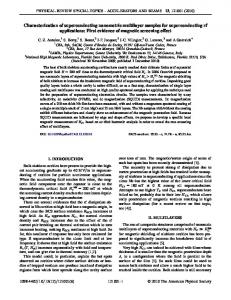
FIG. 1. RADIA Model of the superconducting circular coils, sector coils, and trim coils.
Magnetic radius of spiral inflector Injection energy Number of dees Dee angle rf Frequency rf Mode of operation
040101-2
4 1.735 T 26.42 MHz 2.48 T 1.2 T Negative hydrogen ion Proton with stripper foil, dual beam Maximum energy at �400 mm �14 mm �28 keV 2, in alternative valleys �42� in outer radii �105:68 MHz 4th harmonic
NOVEL COMPACT SUPERCONDUCTING CYCLOTRON . . . be derived by equating the expression for vertical betatron frequency vz to zero [13,14]. The focusing limit is �0:5 � N2 Kf ¼ 150Rext BN ; 2ðN 2 � 1Þ where BN ðTÞ is the amplitude of the Nth harmonic Fourier component of the magnetic field at the extraction radius Rext ðmÞ. As shown in Fig. 4, at Rext ¼ 420 mm, B4 ¼ 0:78 T, which gives Kf ffi 36 MeV=A. With a typical injection energy of 28 keV in an average magnetic field of 1.735 T, the spiral inflector has a magnetic radius of Rm ¼ 14 mm. III. MAGNETIC FIELD SHAPING Magnetic field modeling has been done using based software RADIA [15] and the results have been verified with the finite element magnetostatic code TOSCA also. The RADIA package is essentially a 3D magnetostatic computer code based on boundary integral method, which can solve a variety of problems with linear and nonlinear, isotropic and anisotropic magnetic materials and, of course, with current-carrying elements of different shapes. Figure 1 shows the RADIA model of the sector and circular coils and Fig. 2 shows the same using TOSCA where the magnetic shield is also shown. A fully parametric model of the sector coils and main coils has been used to optimize the geometry in order to generate the near isochronous field, at the same time maintaining the constraints coming from an engineering point of view, e.g., the space required for the cryogenic system (multilayer thermal insulation, radiation shield, etc.), rf system (dee, liner, etc.), spiral inflector and radial penetrations for diagnostic probes, extraction elements, etc. The desired isochronous field as a function of average radius is given by qffiffiffiffiffiffiffiffiffiffiffiffiffiffiffiffiffiffiffiffiffi hBðrÞi ¼ B0 �ðrÞ ¼ B0 = 1 � �ðrÞ2 ; MATHEMATICA
FIG. 2. TOSCA model of superconducting coil cyclotron (SCCCYC) and magnetic shield.
Phys. Rev. ST Accel. Beams 16, 040101 (2013)
where �ðrÞ ¼ !r=c ¼ C3 ðZ=AÞB0 r and C3 ¼ ec=Eamu ¼ 0:32184 T�1 m�1 . The mass (m) of the particle is expressed in terms of mass number A and charge (q) in terms of electronic charge (e), as follows, mc2 ¼ Eamu A and q ¼ Ze. The value of A for a proton is 1.007276 and that for an electron is 0.000548. Neglecting the binding energies of two electrons (13:6 eV þ 0:75 eV), A ¼ 1:008372 is used in calculations for the H� ion. The above formula is valid for closed scalloped orbits in azimuthally varying field Bðr; �Þ also, if the average radius is defined as total path length over the closed orbit divided by 2� [13]. Once the geometrical parameters of sector and circular coils are optimized grossly to obtain this average field profile and sufficient flutter, the finer adjustment of the geometry is done by iteratively investigating the equilibrium orbit properties, as discussed in the next section.
FIG. 3. Contour plot of median plane magnetic field. Contour values (kG) are listed on the right side.
FIG. 4. Fourier harmonic components of magnetic field data. The major flutter components B4 and B8 ensure vertical focusing of beam.
040101-3
DEY, GUPTA, AND CHAKRABARTI
Phys. Rev. ST Accel. Beams 16, 040101 (2013) TABLE II.
Sector coil specification.
Sector coil
Large
Current Sector angle Wire cross section (mm2 ) Inner radiusa Outer radiusa Radial length Number of radial layers Number of turns per layer Distance from median planea a
Flutter of the magnetic field as a function of radius.
Current (A) Inner radiusa Outer radiusa Number of radial layers Number of turns per layer Distance from median planea
FIG. 6. Cross-sectional positions of circular coils, sector coil, and shims in the (r-z) plane.
The iso-Gauss contour plot of the median plane magnetic field data, as shown in Fig. 3, reveals the fourfold symmetry of the magnet. The 4n harmonics (n ¼ 1; 2; . . . ; 5) of the Fourier series analysis of the magnetic field data are shown in Fig. 4. Two smaller size sector coils have been used within the main sector coil. They will be used as trim coils. Adjustment of the cross-sectional position in the (r-z) plane and the number of turns of the sector coils gives a proper distribution of major harmonics B4 , B8 , as well as the average field profile. The flutter of the field, defined by Ffield ðrÞ ¼
85.3 278.3 193.0 1 25 60
Circular coil specification.
Circular coils
a
500 A 22.5� 1:1 � 1:7 83.3 357.4 273 1 20 60
Smallest
All dimensions are in mm. TABLE III.
FIG. 5.
70.3 538.7 468.4 10 50 60
Medium
CC1
CC2
50 57 7 40 82
50 71 19 100 160
MC1
MC2
500 587 597 9 12 70
587 600 12 90 205
All dimensions are in mm.
The average field profile due to the sector coils has a dip near the center, as shown in Fig. 7. Two central coils (CC1 and CC2) have been used at the center of the machine to compensate this dip in the average field profile. Since CC1 is nearer to median plane, its field has a sharper radial gradient than that of CC2. By proper optimization of vertical positions and dimensions of these two coils, a suitable central cone field is generated to enhance vertical focusing in this low flutter central region [16]. At the same time these coils work as a part of the injection system. The major contribution to the average magnetic field comes from the main coils (MC1 and MC2). In this case
hBðrÞ2 i � hBðrÞi2 hBðrÞi2
as shown in Fig. 5, ensures sufficient vertical focusing of the beam. This cyclotron is characterized by relatively higher flutter than conventional high field superconducting cyclotrons [12]. A cross-sectional view of the coils in the (r-z) plane is shown in Fig. 6 and the coil dimensions are listed in Tables II and III.
FIG. 7. Average magnetic field for the sector coils and two central coils (CC1 and CC2).
040101-4
NOVEL COMPACT SUPERCONDUCTING CYCLOTRON . . .
FIG. 8. Average field due to main coils (MC1 and MC2) and the total average field due to all four circular coils and the sector coils. The analytical isochronous field (B_Isoc) is also shown.
Phys. Rev. ST Accel. Beams 16, 040101 (2013)
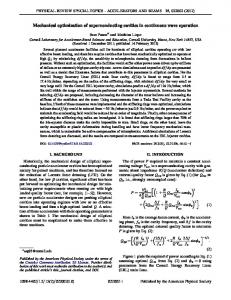
FIG. 10. The graphs show three stages of iterations during minimization of frequency error by fine-tuning the average magnetic field.
the EO coordinates r and pr in terms of � at each energy. It also calculates important EO properties, like orbit period � as a function of energy and the frequencies (vr , vz ) of linear radial and vertical oscillations about the EO. The most important issues related to magnetic field optimization are the frequency error and the focusing of the beam. The frequency error of the equilibrium orbit needs to be small to ensure efficient acceleration throughout the radial range. The frequency error �ðEÞ is defined by �ðEÞ ¼ v0 � � 1 ¼
FIG. 9. Average magnetic field after adding thin iron shims near the center of the cyclotron and at the extraction zone.
also, the difference in radial field gradient between these two coils has been utilized to optimize the radial profile of total average magnetic field very close to the analytical isochronous field, as shown in Fig. 8. Fine-tuning of the magnetic field, in the range of tens of Gauss, has been achieved by adding a-few-mm-thick iron shims near the center and the extraction zone. Figure 9 shows that after fine-tuning the average field profile remains within 40 G from the analytical isochronous field. A central field bump of about 70 G is added by adjusting the central coils and central shims. The shim dimensions are finalized iteratively on the basis of the equilibrium orbit properties.
where ! ¼ 2�=� is the particle revolution frequency, !0 ¼ 2�v0 ¼ 2� � frf =h, frf being the rf frequency and h is the harmonic mode of operation. The particle revolution frequency is given by ! ¼ qB=m, where B is the magnetic field at radius r. By adjusting the iron shim’s thickness and radial position iteratively, a very small frequency error is maintained throughout the acceleration zone. Figure 10 shows three stages of iterations during optimization of the average magnetic field, finally achieving a frequency error within �0:001. The phase � of the ion relative to the radio frequency voltage is defined such that the average energy gain per turn is given by dE=dn ¼ qV cos�, where V is the peak voltage gain per turn. Then the average phase change per turn becomes d�=dn ¼ !rf � � 2�h ¼ 2�h�ðEÞ. Combining these equations, one gets the well-known phase-energy relation: sin�ðEÞ ¼ sin�ðE0 Þ þ
IV. EQUILIBRIUM ORBIT PROPERTIES We have used the code GENSPEO to investigate the equilibrium orbit (EO) properties [17]. In a given median plane magnetic field Bðr; �Þ, this code numerically integrates the canonical equations of motion and iteratively determines
!0 � 1; !
2�h Z E �ðEÞdE: qV E0
The phase curves for the h ¼ 4 and h ¼ 2 modes, with a dee voltage of 50 kV, are shown in Fig. 11. Though the cyclotron is designed to operate in 4th harmonic mode, the
040101-5
DEY, GUPTA, AND CHAKRABARTI
Phys. Rev. ST Accel. Beams 16, 040101 (2013) phase curve in 2nd harmonic mode is also shown for comparison. The linear radial and vertical oscillation frequencies around the equilibrium orbit are shown in Fig. 12. The initial drop in vz values is due to low flutter in the central region. This can be further improved by adjusting the central cone field and for a limited phase range by electric field focusing during acceleration. Figure 13 shows the tune diagram along with various imperfection and coupling resonance curves. It shows that with 200 keV energy gain per turn in the 4th harmonic mode of operation the beam can quickly cross through vr ¼ 2vz and vz ¼ 0:5 resonances. Other resonances do not come before extraction.
FIG. 11. Phase curves for the h ¼ 4 and h ¼ 2 modes of operation with Vdee ¼ 50 kV.
V. ACCELERATED ORBITS, BEAM INJECTION, AND EXTRACTION The accelerated orbits have been calculated using the code [18]. The code solves the equations of motion in a cylindrical coordinate system in a given median plane magnetic field, Bðr; �Þ. The angle � is used as an independent variable; hence, time t is treated as a dependent variable along with position coordinate and momentum ðr; pr ; z; pz Þ. Acceleration in the electric field is simulated as an abrupt change in energy while crossing the dee-to-liner gap, and then the energy remains constant in between two consecutive gap crossings. The location of dee-to-liner gaps are specified by the angles �ij , given by SPIRALGAP
�ij ¼ ði � 1Þ
FIG. 12.
Radial and vertical betatron tunes vs energy.
FIG. 13.
Tune diagram and resonance curves.
2� ð�1Þj D þ þ �c ; Ndee 2
where i ¼ 1; 2 indicates the dee number, j ¼ 1; 2 indicates the entrance and exit of a given dee, Ndee ¼ 2 and �c ¼ 45� . Energy gain is given by Eij ¼ ð�1Þj qV0 sin½!rf tð�ij Þ � ki �, where V0 is dee voltage and ½!rf tð�ij Þ � ki � is the phase of rf voltage for the ith dee. Since the dees are located in alternate valleys, 180� apart, the time required for the particle to travel from the central line of one dee to the central line of next dee is �=2 ¼ �h=!rf . In the 4th harmonic mode of operation the rf phase difference between two dees becomes 4�, i.e., the dee voltages oscillate in phase. Hence, they can be coupled directly at the central region. Though rf phase !rf tð�ij Þ decides the effective energy gain, for easier comprehension of instantaneous acceleration efficiency, a continuous variable ’ð�Þ is used by the program as a part of the input and output. This is called the local acceleration phase and is calculated from ’ð�Þ ¼ !rf tð�Þ � hð�-�c Þ. This is one of the inputs to the code apart from particle’s energy, coordinate, and momentum. Figure 14 shows the initial few turns. The matching point (0.8 MeV) is indicated by a red circle, which is chosen to ensure a well centered beam at higher energies. This is the central line of dee-1, where the particle starts with ðr; pr Þ ¼ ð73:86; 0:014Þ in mm and ’ð�Þ ¼ 0. 040101-6
NOVEL COMPACT SUPERCONDUCTING CYCLOTRON . . .
Phys. Rev. ST Accel. Beams 16, 040101 (2013)
Based on this tentative scheme, the actual central region geometry can be decided considering orbit centering, phase selection, and electric focusing, by adjusting the puller geometry, inflector rotation, etc. The beam extraction calculation is shown in Fig. 15. The stripper position is optimized so that beams with different energy from 15 to 25 MeV reach a common point, where a port selection steering magnet will be positioned. VI. ENGINEERING FEATURES
FIG. 14. The spiral inflector, the projection of the injected beam on the median plane, and the initial few turns are shown. The inflector exit is indicated by a square. The injected orbit is matched to the outer orbit at 0.8 MeV (red circle).
(The momentum of the particle is expressed in length units, i.e., divided by m0 c and multiplied by c=!0 .) It took 127 turns (turn counting starts at 0.8 MeV), in the forward direction, to reach 25.5 MeV at r ¼ 403 mm (not shown in the figure to maintain clarity). To investigate the beam injection feasibility and to decide the tentative size and orientation of the spiral inflector, the particle is tracked backward from the matching point (0.8 MeV) up to the inflector exit. The trajectory is shown in the figure along with the projection of injected beam trajectory inside the spiral inflector. An inflector with magnetic radius of 14 mm and electric radius of 32 mm has been considered here.
FIG. 15. Extracted orbits at 15.7, 20.1, and 25.7 MeV. For clarity, the intermediate accelerated orbits are omitted. The port selection steering magnet at the beam extraction port and the stripper movement line are also shown.
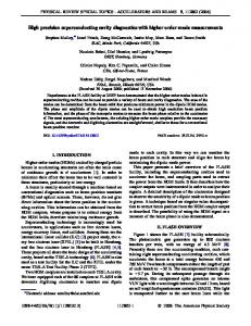
The focus of the engineering considerations has been on ease of fabrication, assembly, maintenance, and operation. Since only superconducting coils are used to produce the isochronous field, it has been possible to design a compact and ultralightweight machine weighing about 2000 kg. The weights of the major components are: former: 250 kg; coils: 200 kg; radiation shield: 150 kg; vacuum chamber: 550 kg; rf system: 200 kg; and external magnetic shield: 630 kg. A 3D conceptual design is shown in Fig. 16. Important engineering features of the main components of the cyclotron are discussed below. A. Coil and cryostat One of the important considerations for the coil is that the cryogenic stability has to be high. The chosen conductor has a 20:1 copper to superconductor ratio resulting in high stability against quenching. There are two ‘‘formers’’ (bobbins), precisely machined out of high strength aluminum alloy blocks. All circular and sector coils are placed
FIG. 16. 3D model of superconducting coil cyclotron, showing different subsystems, as follows: 1. coil cryostat; 2. support link; 3. beam injection port; 4. vacuum port; 5. sliding short between cavity outer and inner conductors; 6. rf liner (outer conductor); 7. dee stem; 8. dee; 9. port for spiral inflector; 10. liquid nitrogen shield; 11. median plane ports for beam extraction, stripper holder, beam diagnostics; 12. port for cryocooler; 13. median plane O-ring joint.
040101-7
DEY, GUPTA, AND CHAKRABARTI
Phys. Rev. ST Accel. Beams 16, 040101 (2013) further shielding is necessary, the field at 0.5 m (outside the first shield) may be reduced to 20 G by adding another iron cylinder of 6 mm thickness and 1200 mm radius weighing about 820 kg around the first one. The shielding cylinders are external to the main cyclotron. They can be made in two halves, allowing easy access to the cyclotron. B. Cooling
FIG. 17. Intensity distribution of magnetic field induction jBj in the coil and outside the magnetic shield (length in cm and field in Tesla).
on the formers with the necessary clamps and supporting fixtures for preventing their movement during energization of the coils. The estimated force on the coils is calculated based on a 4 T magnetic field and the formers are designed accordingly. The actual maximum magnetic field in the coils is 3.7 Tas shown in Fig. 17. It is also very important that the resultant horizontal forces on the former balance out because of the fourfold symmetry. As there are no iron poles, the interaction force on the coils, which is an important consideration in conventional superconducting cyclotron design, is comparatively insignificant. Thus, an elaborate coil alignment process during energization may be avoided. The support links, made out of glass epoxy, hold the former inside the vacuum chamber. A 50 K thermal intercept from the cryocooler 1st stage is provided to the support links for reducing the heat load to the coils. The optimized cold mass is about 450 kg at 4.2 K and 150 kg at 50 K. The upper and lower formers are rigidly supported at the median plane, outside the beam acceleration zone, with four solid blocks to take care of the magnetic loading between the upper and lower coils. These supports are demountable so that two halves are easily separable for access to the median plane. An external iron cylinder is used for magnetic shielding. Figure 17 shows the magnetic field distribution in the superconducting coil region and beyond the shield. With a 6 mm thick iron cylinder of 900 mm radius and 1500 mm height (weight 630 kg), the fringing field is reduced to 137 G at 0.5 m outside the shield. This is a value suitable for cyclotron operation with some local shielding for magnetic elements, pumps, and other instruments situated nearby. The advantage of using the external iron cylinder for magnetic shielding is that it is at room temperature, unlike the Oxford Instrument’s cyclotron, where the iron cylinder in association with a bucking coil is within the liquid helium cryostat. So the cold mass in this design is substantially reduced. Calculations have shown that, if
There are four cryocoolers, two at the top and two at the bottom, for cooling the coil blocks. Each of the cryocoolers will have cooling capacity of 35 W at 50 K (1st stage) and 1.5 W at 4.2 K (2nd stage). The 1st stage will be used to cool the thermal shield and the intercepts. For cooling, one can use either the conduction cooling technique or the recondensation-type bath cooling technique. The conduction cooling system is more interesting for its simplicity and robustness, apart from leading to a design of lesser weight. The mechanical vibrations can be isolated from the coils with flexible thermal connections. The heat load for this configuration is estimated to be about 4 W at 4.2 K with a 50 K radiation shield and 50 K intercepts for the conduction links. The eddy current power dissipation in the Al-alloy former is calculated to be about 4 mW when the coils are ramped to 500 A in 2 hours. The heat load can be reduced with further optimization. The redundancy in the number of cryocoolers will allow the cyclotron to run in case any one of the cryocoolers fails. This is important for its medical use so that the cyclotron up-time is high. It is also necessary to make demountable joints for the cryocoolers for easy replacement. With all the four cryocoolers on, the cooling capacity is about 6 watts at 4.2 K. C. rf cavity The rf cavity will operate at �106 MHz, and will have a coaxial TEM structure. The cavity will be made out of normal conducting copper structure operating at room temperature. Water cooling will be provided to the parts of the inner and outer conductors where the radio frequency currents are high. A preliminary 3D modal analysis of the cavity has been done using the software ANSYS to calculate its tentative dimensions. D. Assembly and maintenance A central hole provides the path for entry of the ion beam into the center of the cyclotron from an external H� ion source. The vacuum chamber would be made in two halves, with a large ‘‘O’’ ring sealing near the median plane of the cyclotron. All the components, e.g., supports for coil formers, rf cavities, etc., will be attached to the top and bottom plate of this chamber. This will help in installation and maintenance of the cyclotron just by splitting the two halves of the vacuum chamber, which will allow full access to the median plane. The assembly of this cyclotron is easier than for a
040101-8
NOVEL COMPACT SUPERCONDUCTING CYCLOTRON . . . conventional superconducting cyclotron, as the latter’s iron poles and return yoke restrict the approach to different parts. E. Magnetic field measurement A jig with a vacuum compatible motor will drive the search coil measuring arm and make a full polar scan of the magnetic field inside the machine. The sensor output will be taken out via a vacuum feedthrough from the top/bottom plate of the vacuum chamber. The advantage of a coilbased cyclotron is its linearity in magnetic field with current, thus reducing significantly the effort required in field measurement and corrections. VII. CONCLUSION In this paper we have presented a new design of an ultralight low energy medical cyclotron based on superconducting coils, which weighs only about 2000 kg and has all the desirable features of an accelerator for medical isotope production. The speciality of this design lies in eliminating the iron yoke and poles altogether. The azimuthal varying field is generated by superconducting sector coils. Independently powered superconducting circular coils and sector coils are used to generate the desired magnetic field shape. This further provides flexibility of operation through on-line trimming of the magnetic field. All the coils are accommodated in a single cryostat. The basic size and shape of the other subsystems, e.g., spiral inflector, rf system, cryogenic system, extraction system, etc., have been estimated realistically and the magnet design has been optimized taking into consideration all the other subsystems. Detailed calculations of equilibrium and accelerated orbits have been presented, along with beam injection and extraction feasibility check. A conceptual engineering design has also been worked out to check the feasibility of the design from the engineering point of view. ACKNOWLEDGMENTS We thank Shri Sutripta Sur for preparing the 3D engineering model of the superconducting coil cyclotron presented in this paper.
Phys. Rev. ST Accel. Beams 16, 040101 (2013)
[1] T. Stammbach et al., in Proceedings of the 8th European Particle Accelerator Conference, Paris, 2002 (EPS-IGA and CERN, Geneva, 2002), p. 159. [2] Y. Jongen et al., in Proceedings of the Fourth European Particle Accelerator Conference EPAC 94, London, England (World Scientific, River Edge, NJ, 1994), p. 2627. [3] M. Abs et al., in Proceedings of the 14th International Conference on Cyclotrons and their Applications, Cape Town, South Africa, 1995, edited by John C. Cornell (World Scientific, Singapore, 1996), p. 120. [4] Y. Jongen, J. L. Bol, A. Chevalier, M. Lacroix, and G. Ryckewaert, Nucl. Instrum. Methods Phys. Res., Sect. B 24/25, 813 (1987). [5] Katherine Gagnon et al., Nucl. Med. Biol. 38, 907 (2011) [http://www.elsevier.com/locate/nucmedbio]. [6] M. F. Finlan, M. Kruip, and M. N. Wilson, in Proceedings of the 11th International Conference on Cyclotrons and their Applications, Tokyo, 1987, edited by M. Sekiguchi, Y. Yano, and K. Hatanaka (Ionics Publishing, Tokyo, 1987), p. 689. [7] H. G. Blosser, Nucl. Instrum. Methods Phys. Res., Sect. B 24/25, 752 (1987). [8] U. Trinks, Nucl. Instrum. Methods Phys. Res., Sect. A 287, 224 (1990). [9] U. Trinks, Nucl. Instrum. Methods 220, 186 (1984). [10] John H. Ormrod, Nucl. Instrum. Methods Phys. Res., Sect. A 244, 236 (1986). [11] R. Griffiths, Nucl. Instrum. Methods Phys. Res., Sect. B 40/41, 881 (1989). [12] H. G. Blosser and D. A. Johnson, Nucl. Instrum. Methods 121, 301 (1974). [13] T. Stammbach, PSI, Switzerland, CERN Yellow Report No. 96-02, p. 113. [14] Y. Jongen and S. Zaremba, CERN Yellow Report No. 96-02, p. 139. [15] P. Elleaume, O. Chubar, and J. Chavanne, in Proceedings of the Particle Accelerator Conference, Vancouver, BC, Canada, 1997 (IEEE, New York, 1997), p. 3509. [16] P. G. Watson, Nucl. Instrum. Methods 18, 362 (1962). [17] GENSPEO, NSCL, MSU, East Lansing, USA. [18] M. M. Gordon, Nucl. Instrum. Methods 169, 327 (1980).
040101-9