value, but also the variation trend of the receiving power of the beacon signals. This protocol provides a low rate of failed packet due to the mobility of the.
NOVEL MULTIPLE ACCESS SCHEME FOR WIRELESS SENSOR NETWORK EMPLOYING UNMANNED AERIAL VEHICLE Tu Dac Ho, Jingyu Park, and Shigeru Shimamoto Waseda University, Tokyo, Japan
Abstract This paper proposes a new MAC protocol applied for a new kind of data collection applications that use a wireless sensor network employed with one unmanned aerial vehicle (WSN-UAV). In this protocol, the sensors are classified in different groups based on priorities and communicate with the UAV by a CDMA-based transmission scheme. The Prioritized Frame Selection based CDMA MAC protocol (PFSC-MAC 1 ) incorporates not only the value, but also the variation trend of the receiving power of the beacon signals. This protocol provides a low rate of failed packet due to the mobility of the UAV, which is the most critical metric in these types of applications. In addition, an optimal number of priority groups have also been introduced to guarantee a minimal transmission interval and a lowest failed packet ratio. Numerical results have also shown the efficient energy compared with the other protocol that is based on TDMA. This protocol is simple but promising for various applications that collect data from a large area sensor network.
Introduction In this paper, we focus on WSN-UAVs that consist of a large area wireless sensors network and one unmanned aerial vehicle [1]. These WSN-UAVs are able to perform many kinds of applications in practical fields [2,3]. The major challenge of WSNUAVs is the medium access control protocol that guarantees high network throughput, low energy consumption, and a small time interval for sending data [4]. The latency of data transmission between the sensors and the UAV is not concerned because it uses direct communication, as opposed to the multi hop communication employed in other WSNs. This paper introduces a PFSC MAC protocol for WSN-UAV systems that incorporate a novel 1
The preliminary content of this proposal has been accepted by IEEE GLOBECOM, International Workshop on Wireless Networking for Unmanned Aerial Vehicles, Miami, Dec. 2010.
978-1-4244-6618-4/10/$26.00 ©2010 IEEE
Prioritized Frame Selection (PFS) scheme to control the transmission priority of the sensors and leverage CDMA in the physical layer. The purpose is to guarantee that a large number of active sensors transmit their data while the UAV is still within the communication range. We also introduce an average traffic-based algorithm aimed to determine a period of time needed for a specific number of sensors to successfully access the channel. To the best of our knowledge, this is the first protocol that utilizes PFSC-MAC for sensor applications. Since the UAV is moving, the connection time between the sensors and the UAV is limited, and a prioritized frame selection based scheme like the one mentioned in this paper is crucial for WSN-UAV systems. The remainder of this paper is organized as follows. The next section discusses the related works regarding WSN-UAVs and their remaining issues. The model of our protocol and its operation are fully explained in the section of protocol description. The section of system performance evaluation provides numerical results of our PFSC-MAC protocol in terms of system performance and the optimal number of the priority groups. Final remarks are concluded in the last section.
Related Works There has been intensive research on MAC protocols for multi hop ad hoc, and wireless sensor networks [5,6]. However, WSN-UAV system is different with the existing of the UAV. One of our studies has shown that IEEE 802.11 CSMA/CA is not suitable for WSN-UAV systems [7], even though it has been widely used in WLAN systems and WSNs [8,9]. This is because of two reasons: overhead burden on the low-power sensors, and the wellknown hidden terminal effect. TDMA has been proposed for WSNs but it is mainly employed for reducing energy consumption [10-12] . CDMA is a promising MAC protocol for WSNs, and several advantages have been shown in [13,14]. FDMA is not suitable for WSNs due to stringent synchronization in the frequency domain [15]. In
5.C.5-1
general, these MAC protocols are only tailored for WSNs that entirely use multi hop ad hoc networking. Therefore, they may be not suitable for such a centralized and single hop system, like WSN-UAV system. Regarding multi-carrier transmission, a study was performed for WSNs employing a high altitude platform [16]. This system has a similar architecture with WSN-UAVs. However, this system is not suitable for WSN-UAVs because sensor-complexity increases energy usage and our system do not require sending lots of data as assumed in [16]. More specifically, CDMA has also been discussed for WSN-UAV systems [17-21]. However, in these systems only a few sensors are transmitting at a given time, and only the sensors that get the highest channel gains are used as transmitting sensors. These gains are of the links between the UAV and the sensors. In order to increase the number of transmitting sensors, the time period needed for data transmission must be significantly large [22]. Conversely, in our system a large group of sensors transmit data simultaneously and distinguishably in a short interval, which is more suitable for many applications of WSN-UAV systems. For example, it may be critical to obtain as much data as possible after a natural disaster from a wide range of area very quickly. A comparison in system performances of our system with the system in [17-21] is not suitable because our objectives in data collection are different. For instance, to carry out a data collection from all the sensors in the proposed systems, the UAV must repeat its flight several times, which takes time, cost, and there is no guarantee of all needed data is fully collected.
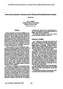
Protocol Description Architecture and Operation of WSN-UAV System In Figure 1, there are a large number of lowpower sensors that are randomly deployed on a wide geographical area. The UAV is equipped with a beacon generator which is used to generate a beacon signal to activate. The sensing data from the activated sensors is retrieved by the UAV. To save energy, all the sensors are turned off when the beacon signal is not available, or is weaker than the receiving threshold. To carry out data collection, all the activated sensors need to transmit their sensing data
to the UAV periodically in every data transmission interval. The flight path of the UAV could be fixed or random depending on application scenarios. In this paper, it is assumed that the UAV follows a static route as shown in Figure 1. Flare angle of the beacon signal UAV’s flight path Beacon signal Activated sensor (ON)
h
sensors send data to UAV
2R
Effective area of beacon signal or its footprint (radius: R)
Un-activated sensors (OFF)
Figure 1. General Description of a WSN-UAV System The most favorable features of sensor applications using WSN-UAV are its simplicity, efficiency in data collection, and energy efficiency for the sensors. In fact, WSN-UAV systems have several physical advantages compared with normal WSNs [18]. In addition, the propagation path loss between ground-sensors and the UAV is almost in line-of-sight. This situation is relatively similar to the case of air traffic control towers and commercial aircrafts as in our previous studies [23-25]. In the worst case, the exponent path loss is still small, about 2.25. Sensor to sensor has been shown to be inefficient as the signal decays to the fourth power of distance between any two sensors on the ground [26]. By using direct communication between the sensor and UAV instead of a relay network of sensors, WSN-UAVs have relieved the sensors from energyconsuming tasks.
Prioritized Frame Selection MAC (PFS-MAC) Protocol As mentioned in Sect. II, the number of concurrent transmitting sensors in [17-21] is always a small part of the active sensors. In our protocol, all the active sensors transmit data. In addition, the active sensors are divided into several groups, where each group is assigned with a particular transmission priority. There are two parameters used to prioritize the activated sensors into several groups. One parameter is the power value of the receiving beacon signal. The other parameter is the varying trend of the receiving beacon signal’s power value. The latter
5.C.5-2
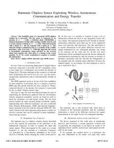
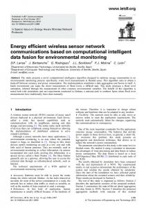
parameter contributes to our PFS-MAC, which makes the protocol novel and more robustness against to the mobility of the UAV. This trend could be increasing (_I) or decreasing (_D) as described in Figure 2. The increasing trend implies that the UAV is approaching to the sensors. Conversely, the decreasing trend implies that the UAV is leaving the sensors. To detect this trend, we assume that each sensor always records and stores an array of power values. These values are used to compare with the newest value, and the trend can be determined. The regulations are guided as follows: to the decreasing power value groups, the lower power group the higher priority of transmitting; and to the increasing power value groups, the higher power group the higher priority of transmitting. For example, the transmission orders from the highest to lowest of the priority groups in Figure 3 are as follows: p.g.1_D, p.g.2_D, p.g.3_D, p.g.3_I, p.g.2_I, and p.g.1_I. Accordingly, the priority frames are as follows: p.f.1_D, p.f.2_D, p.f.3_D, p.f.3_I, p.f.2_I, and p.f.1_I.
For starting the priority groups division, we assume that the following information is predefined: the number of priority groups, the average number of sensors per priority group, and other parameters as described in the algorithms in the next sub section C. After the active sensors are divided into groups, the activities of the sensors in the highest priority group will start. These activities include channel access and data transmission as in Figure 4. The next part briefly discusses these activities, specifically in the applicability of the two cases of using TDMA and CDMA for transmission in the physical layer for each priority group. Transmission probability
t+T_pf
p.f.1 d.t. 1
Channel Methods
Flight path
Leaving area
Figure 2. The Increasing and Decreasing Groups Rx power 3
Transmission priority
Decreasing
1
_D
Distance (sensor to UAV) Level 1
0 3 Level
_I
_I
Inner part Outer part
p.f.3
_I
p.g.2
p.g.1
p.f.1_I
p.f.2_I
p.g.3
D
_ p.g.3
_D
p.g.2
p.g.1
2
1 p.f.3_I p.f.3_D p.f.2_D
t Time (s)
c.a. 3 d.t. 3 Data transmission 3 ….. T_dt
Figure 4. Structure of an Interval Frame
Active sensor
Level 2
p.f.2
T_ca: duration of TS in channel access T_dt: duration of TS in data transmission
Beacon area UAV
2
p.g.3
ing
Inc
as
rea
cre
sin
g
De
T_ca
Distance (sensor-UAV)
Increasing
p.g.2
c.a. 1
Channel access 1 …..
Rx power
Approaching area
p.g.1
p.f.1_D
Time
Interval frame
Figure 3. Prioritized Frame Selection Scheme
Access
and
Data
Transmission
In order to access the channel, each sensor needs to successfully transmit a header to the UAV. This header contains at least the sensor’s ID, the receiving beacon signal power, the priority group ID, and the sensor’s position etc., if needed. If the UAV receives this header successfully, the UAV will send feedback to that transmitting sensor immediately. Because the sensors’ positions in WSN-UAV systems are randomly distributed; hence the number of sensors in each group is arbitrary. Therefore, the channel access method needed to be able to adapt to a variable number of sensors. If CSMA/CA is used for accessing the channel, in order for each sensor to successfully send a header, the time duration for channel access has to be extremely large [13]. For example, we assume the
5.C.5-3
time needed to send a header and to receive an acknowledgement is 𝑇ℎ𝑒𝑎𝑑𝑎𝑐𝑘 , and the period of time used for channel access is 𝑑 = 𝑁𝑇ℎ𝑒𝑎𝑑𝑎𝑐𝑘 . Then, the probability that no contention occurs in a wireless −3𝑘(𝑘−1) 2𝑁
channel is greater than 𝑒 , where k denotes the number of nodes that contend the channel [27]. Therefore, in order to obtain a high probability of no channel contention, N has to be large. As a result, the time used for channel access (d) is also large. This is not a concern for conventional WSNs; however, it is definitely not suitable for WSN-UAV systems because the connection time is limited. Therefore CSMA/CA is not suitable for channel access in WSN-UAV systems.
This part introduces the applicability and comparison of the two PFST-MAC (PFS based TDMA MAC) and PFSC-MAC (PFS based CDMA MAC) protocols. In the case of PFST-MAC, the feedback contains information of the timeslot that the sensor uses to transmit data. In addition, the sensors randomly select a timeslot among a number of available timeslots informed by the UAV. Each sensor transmits its header on the selected timeslot. The header at least contains following information of the sensor, such as the actual position, its own priority group, sensor’s ID, etc. This mechanism is repeated until all the sensors correctly receive an acknowledgement from the UAV (the ACK of the header’s transmission). For the case of PFSC-MAC, in channel access period, all the sensors contend the channel to communicate with the UAV by an assigned common code (C0) which is predefined in the system. The feedback in this case will include a random pseudo random code Ci that the i-th sensor uses to spread its data signal. It has been shown that, the system performances in the PFSC-MAC are better than that in the PFSTMAC [28]. For instance, the interval frame lengths in PFSC-MAC protocol are always shorter than that in PFST-MAC protocol under the same conditions of sensors density, altitude, the UAV’s speed, etc. In addition, the frame length in the case of PFSC-MAC only slightly depends on the size of the packet (that each sensor transmits data to the UAV each time) and the speed of the UAV, especially at the high number of sensors in the network [28]. These factors are advantageous for the applications that request short data transmission interval in a large area, and need a large packet size. Therefore, only PFSC-MAC
protocol is applied for system performance evaluation described in the next section.
System Performance Evaluation Simulation Parameters and Metrics Table 1. Simulation Parameters of the PFSC-MAC Parameters The area (m2) # sensors # priority groups UAV’s altitude (m) Beacon’s flare angle (0) UAV’s speed (m/s) UAV’s moving path Standard deviation (for the receiving beacon’s signal at the sensor) (dB) Exponent path loss (sensor to UAV and sensor to sensor) System loss (dB) Transmission range (m) Packet size (bytes) Data bit rate (kbps) Transmission interval (s) Receiving threshold (W) Sensing threshold (W) Carrier frequency (Hz) Rice factor (K) (dB) Bandwidth (MHz) Modulation Energy for transmission, reception, idle, and sleep mode (mW) Channel access and data transmission
Values 300x300 50 ÷ 400 3 50 ÷ 200 60 10, 30 (Figure 1) 2 2, 4 1 20 25, 100 25 2 1E-10 1E-11 1.2E9 11 5 QPSK 14.88, 12.50, 12.36, 0.016 CDMA based
In the simulations, we assume that there are from 50 to 400 sensors randomly located in an area of 300x300 m2 [29]. The transmitting power is calculated based on the condition that the receiving powers at the active sensors are always larger than or equal to the receiver threshold (Table 1). An important parameter in our protocol is the number of priority groups. In this simulation, we temporarily use 3 priority groups. The optimal selection for this parameter will be further analyzed. The length of spreading codes used for spreading the sensed data by each sensor is designed to have a number of codes that are enough for all the sensors in any priority group. For system design, this issue does not make a problem for the WSN-UAV system because the UAV requests the active sensors to initialize the codes with
5.C.5-4
an appropriate length, which depends on the actual number of sensors in a priority group. The modulation of QPSK is typically selected for CDMA system. The transmission range of the sensor is normally selected at 20 meters; and the flare angle of the antenna on the UAV is assumed at 60 degrees (See Figure 1). The channel between the UAV and the sensors is assumed to follow the Rice distribution, with K factor at 11 dB; the standard deviation of receiving power values of beacon signal is assumed at 2 dB [30]. The other parameters values in the simulation are as in Table 1. The system performance will be evaluated by the following metrics: interval frame length, packet failed ratio, and time usage for different modes at each sensor. The interval frame length also means the minimum interval that the sensors can perform their data transmission. Usually, the data transmission interval is one or several seconds, which depends on the particular application. The failed packet ratio is the ratio between the failed packets and the total packets transmitted by the active sensors within one interval frame. The failed packets in this case are mainly caused by the mobility of the UAV, specifically due to the Doppler-effect and the link availability issues. The last metric is related to the average energy consumption because energy consumption is directly related to the mode the sensors are in. Since we cannot measure power usage in the simulations, we measure the total time that each sensor expenses on a specific mode. The two general modes concerned are active and idle. However, the active modes include transmission, reception, and overhearing. For the time conversion between other various modes (in transmission mode) and the actual one, we apply these ratios as following: transmission: reception: overhearing = 1:0.84: 0.83 [31]. It is noted that, in the simulations results, we have used following symbols: h, pk, act per, and idle per, that stand for the altitude of the UAV, packet size, the active mode period, and the idle mode period, respectively.
Evaluation of the PFSC-MAC Protocol The results in Figure 5 show that, the frame length only slightly depends on the size of the packet and the speed of the UAV, especially at the high
number of sensors in the network. Therefore, PFSCMAC protocol is advantageous for the applications that request short data transmission interval in a large area, and need a large packet size. h=50 m, pk=25 bytes
h=100 m, pk=25 bytes
h=150 m, pk=25 bytes
h=200 m, pk=25 bytes
h=50 m, pk=100 bytes
h=100 m, pk=100 bytes
h=150 m, pk=100 bytes
h=200 m, pk=100 bytes
2.00
1.00
Interval frame length (s) UAV's speed: 30 m/s
0.50
0.25
0.13 50
100
150
200
250
300
350
400
The number of sensors in the entire network
Figure 5. Interval Frame Length Figure 6 shows the failed packet ratios of the system at the speed of 30 m/s and at two altitudes of 50 and 200 meters, which does not depend much on packet size. Nonetheless, the failed packet ratio slightly increases with the UAV’s altitude, and increase in the number of sensors in the network. Therefore, to meet a specific requirement on failed packet ratio, it is easy to find an optimal configuration for operating the UAV as well as the sensor network. For instance, by analyzing more of the simulation results: it can be determined that if the UAV’s speed is 10 m/s, with a packet size of 25 bytes, to guarantee a failed packet ratio less than 1%, the maximum altitude of the UAV must be 100 meters if there are up to 400 sensors in the network. If there are only up to 200 sensors, the maximal altitude of 200 meters is still possible to guarantee this failed packet ratio. In addition, the UAV can still fly at higher speeds, i.e. 30 m/s. However, at this new speed, the UAV’s altitude must be less than 100 meters if there are about 400 sensors in the network, or the UAV can increase its altitude up to 150 meters if the number of sensor is about 200. It is noted that, the interval frame lengths at 10 m/s are not shown because they are similar with the results shown in Figure 5. For the failed packet ratios at 10 m/s, the results are approximated 3 times better than the results shown in Figure 6 (at the UAV’s speed of 30 m/s).
5.C.5-5
h=50 m, pk=25 bytes
h=100 m, pk=25 bytes
h=150 m, pk=25 bytes
h=200 m, pk=25 bytes
h=50 m, pk=100 bytes
h=100 m, pk=100 bytes
h=150 m, pk=100 bytes
h=200 m, pk=100 bytes
6.3% 3.1%
Percentage of failed packet UAV's speed: 30 m/s
1.6% 0.8% 0.4% 0.2% 50
100
150
200
250
300
350
400
The number of sensors in the entire network
Figure 6. Failed Packet Ratio Figure 7 shows the time usages in active and idle modes of each sensor when the packet size is 25 bytes and the UAV’s speed is at 30 m/s. At the slower speed of 10 m/s, the periods of time for each mode will be almost 3 times larger than the results in Figure 7. This is because the connection time in the lower speed case is 3 times larger than that in the higher speed case. h=50 m, active period h=100 m, idle period h=200 m, active period
h=100 m, active period h=150 m, idle period
h=50 m, idle period h=150 m, active period h=200 m, idle period
4
Time usage in active and idle mode (s) The UAV's speed: 30 m/s
3.5 3 2.5 2 1.5 1 0.5 0 50
100
150
200
250
300
350
400
The number of sensor in the whole network
Figure 7. Time Usage in Active and Idle Modes (pk=25 bytes and UAVspeed = 30 m/s)
The Optimal Selection of the Number of Priority Groups In the evaluations described above, the number of priority groups has only assumed at 3 (Table 1). However, in order to find the best division for priority groups, it is necessary to find the optimal value in each case of the altitude, speed of the UAV
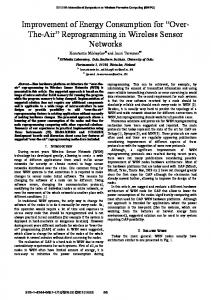
and the packet size, the number of sensors in the system, etc. Because the energy consumption is always proportional to the interval frame length when the number of priority groups is varied. Therefore, when the system simultaneously obtains a minimum interval frame length and a minimum failed packet ratio, we have the optimal number of priority groups. To find the optimal value, additional simulations have been conducted at several values of the number of priority groups, i.e. ranging from 1 to 13; other parameters are the same as those in Table 1. Figure 8 shows the interval frame length and failed packet ratio at the speed of 10 m/s, the two altitudes of 50 and 200 meters, and at two values of the number of sensors in the network of 50 and 400. The results at the speed of 30 m/s are not shown but are used for making a comparison. From Figure 8, a general trend to realize the optimal priority groups is drawn. For any of following conditions: a higher speed of the UAV, a higher UAV’s altitude, a larger number of sensors, or a lower failed packet ratio, a larger number of priority groups is optimal. For example, at a low altitude of 50 meters and only 50 sensors in the network, the frame length increases with an increase of the number of priority groups. However, the failed packet ratio at these conditions does not change with changing of the number of priority groups. Figure 8 shows that, the optimal number of priority groups can be seen as 1 when both frame length value, and failed packet ratio are minimal. In addition, at the higher altitude of 200 meters but the same number of sensors in the network, both frame length and failed packet ratio are minimal at 3 priority groups (and 5 groups at the speed of 30 m/s). Similarly, at the same altitude of 200 meters but the higher number of sensors in the network of 400, the optimal number of priority groups has to be at 11 (and 13 groups at the speed of 30 m/s). In general, for particular conditions of: the required data transmission interval, the UAV’s altitude, the number of sensors in the network, the UAV’s speed, and packet size, the optimal number of priority groups can be determined.
5.C.5-6
Frame: h=50m, n=50
Frame: h=50, n=400
Frame: h=200, n=50
Frame: h=200, n=400
Failure: h=50, n=50
Failure: h=50m, n=400
Failure: h=200, n=50
Failure: h=200m, n=400
4.00
100.0%
(n: number of sensors in the network)
50.0% 25.0% 12.5%
1.00
6.3%
Optimum for h=50; n=50
0.50
3.1% 1.6%
0.25
0.8%
0.13
0.4% Optimum for h=200; n=50
0.06
0.2%
Optimum for h=200; n=400
0.1%
0.03
Percentage of failed packet
2.00
Interval frame length (s)
Power Wireless Sensors,” Proc. XIX Congresso Nazionale AIDAA, Vol. 86, pp. 141-150, Forli, Italy, Sep. 2007.
0.0% 1
3
5
7
9
11
13
The number of priority groups for division
Figure 8. Optimal Values of the Number of Priority Groups (pk= 25 bytes and UAVspeed= 10 m/s)
Conclusion This paper proposes a novel Prioritized Frame Selection based CDMA MAC protocol (PFSC-MAC) used for WSN-UAV systems. This protocol could be applied for various sensor applications in data collection that has become widespread in industry. For any particular requirement on failed packet ratio, we can find the optimal conditions for operating the UAV (i.e., altitude and ground speed), and the sensors network (i.e., packet size and data transmission interval). In addition, an optimal selection for the number of priority groups based on the UAV’s altitude and the number of sensors in the network is introduced. Moreover, we can employ energy saving by carrying out the on/off scheme, where the sensors are only on when in active mode and are off while idle. As shown in the results section, the time in active mode is significantly shorter than the time in idle mode. Therefore, the lifetime of the overall sensor network is also prolonged. In order for this protocol to be accurate and practical to different application environments, other studies for channel characteristics in different conditions have been conducted. Also, based on our single hop protocol, a multi hop protocol is being extended and developed with the cases of single and multiple UAVs. These protocols are definitely promising to use in these new WSN-UAV systems and other similar architecture systems.
References [1] M. Lucchi, A. Giorgetti, M.Z. Win, and M. Chiani “Using A UAV to Collect Data From Low-
[2] Mainwaring, J. Polastre, R. Szewczyk, D. Culler, and J. Anderson, “Wireless Sensor Networks for Habitat Monitoring,” Proc. of Workshop on Wireless Sensor Networks and Applications (WSNA), pp. 8897, Atlanta, GA, Sep. 2002. [3] R. Jafari, A. Encarnacao, A. Zahoory, F. Dabiri, H. Noshadi, and M. Sarrafzadeh, “Wireless Sensor Networks for Health Monitoring,” Proc. Mobile and Ubiquitous Systems: Networking and Services , pp. 479-481, Jul. 2005. [4] Demirkol, c. Ersoy, and F. Alagoz, “MAC Protocols for Wireless Sensor Networks: A Survey,” IEEE Commun. Mag., Vol. 1, pp. 115-121, Apr. 2006. [5] J. Akyildiz, W. Su, Y. Sankarasubramaniam, and E. Cayirci, “A Survey on Sensor Networks,” IEEE Commun. Mag., Vol. 40, pp. 102-114, Aug. 2002. [6] Chandra, V. Gummallam, and J. Limb, “Wireless Medium Access Protocols,” IEEE Commun. Surveys, 2002. [7] J. Park, T.D. Ho, S. Shimamoto, “Wireless Sensor Networks Employing Unmanned Aerial Vehicle,” IEICE Tech. Rep., Vol. 110, No. 8, SANE 2010-5, pp. 25-30, Okinawa, Japan, Apr. 2010. [8] B. P. Crow, I. Widjaja, J.G. Kim, and P.T. Sakai, “IEEE 802.11 Wireless Local Area Networks,” IEEE Commun. Mag., Vol. 33, pp. 116-126, Sep. 1997. [9] J. Polastre, J. Hill, and D. Culler, “Versatile Low Power Media Access for Wireless Sensor Networks,” ACM Conf. on Embedded Networked Sensor Systems, pp. 95-107, Baltimore, Nov. 2004. [10] M. Arumugam, and S.S. Kulkarni “SelfStabilizing Deterministic Time Division Multiple Access for Sensor Networks,” Journal of Aerospace Computing, Information, and Communication, Vol. 3, Aug. 2006. [11] W.B. Heinzelman, A.P. Chandrakasan, and H. Balakrishnan, “An Application - Specific Protocol Architecture for Wireless Micro Sensor Networks,” IEEE Trans. Wirel. Commun., Vol. 1, No. 4, pp. 660670, Oct. 2002.
5.C.5-7
[12] C. Taddia, N. Meratnia, L.F.W. van Hoesel, G. Mazzini, and P.J.M. Havinga, “MAC Support for High Density Wireless Sensor Networks,” in Proc. IEEE 15th SoftCOM, pp. 182-189, Dubrovink, Croatia, Sep. 2007.
[23] T.D. Ho, and S. Shimamoto “A Proposal of Wide-Band Air-to-Ground Communication at Airports Employing 5-GHz Band,” Proc. IEEE WCNC, pp. 1777-1782, Budapest, Hungary, Apr. 2009.
[13] B. Hua Liu, M. Bulusu, H. Pham, and S. Jha, “CSMAC: A Novel DS-CDMA Based MAC Protocol for Wireless Sensor Networks,” Proc. IEEE GLOBECOM, pp. 1-6, Dec. 2004.
[24] T.D. Ho, and S. Shimamoto “A proposal of a Wide-Band for Air Traffic Control Communications” Proc. IEEE WCNC, pp. 1950-1955, Las Vegas, Nevada, Apr. 2008.
[14] T. Shu, and M. Krunz, “Energy-Efficient Power/Rate Control and Scheduling in Hybrid TDMA/CDMA Wireless Sensor Networks,” Int. J. Comput. Telecom. Network., Vol. 53, No. 9, pp. 1395-1408, Jun. 2009.
[25] T.D Ho, J. Park, S. Shimamoto, and J. Kitarori “Oceanic Air Traffic Control Based on Space-Time Division Multiple Access,” Proc. IEEE/AIAA 28th DASC, 7.D.2-1 - 7.D.2-13, Orlando, FL, Oct. 2009.
[15] M. Salajegheh, H. Soroush, and A. Kalis, “HYMAC: Hybrid TDMA/FDMA Medium Access Control Protocol for Wireless Sensor Networks,” IEEE PIMRC, pp. 1-5, Athens, Greece, Sep. 2007. [16] Z. Yang, and A. Mohammed “A Study of Multiple Access Schemes for Wireless Sensor Network Application via High Altitude System,” in Proc. IEEE 69th Veh. Tech. Conf., pp. 1-5, Spring 2009. [17] P. Venkitasubramaniam, S. Adrieddy, and L. Tong, “Sensor Network With Mobile Access: Optimal Random Access and Coding,” IEEE J. Sel. Areas Commun., Vol. 22, No.6, Aug. 2004 [18] G. Mergen, Q. Zhao, and L. Tong, “Sensor Network With Mobile Access: Energy and Capacity Consideration,” IEEE Trans. Commun., Vol. 54, No.11, Nov. 2006 [19] L. Tong, Q. Zhao and S. Adireddy, “Sensor Networks with Mobile Agents,” Proc. MILCOM, pp. 688-693, Oct. 2003. [20] P. Venkitasubramaniam, S. Adireddy, and L. Tong, “Opportunistic ALOHA and Cross Layer Design For Sensor Networks,” Proc. MILCOM, pp. 705-710, Oct. 2003. [21] Q. Zhao and L. Tong, “Quality-Of-Service Specific Information Retrieval For Densely Deployed Sensor Network,” Proc. MILCOM, pp. 591-596, Oct. 2003.
[26] K. Sohrabi, B. Manriquez, and G. J. Pottie “Near Ground Wideband Channel Measurement,” Proc. IEEE Veh. Tech. Conf., pp. 571-574, Jul. 1999. [27] D.M. Blough, M. Leoncini, G. Resta, and P. Santi, “The k-Neigh Protocol for Symmetric Topology Control in Ad Hoc Networks,” Proc. IEEE MobiHoc 2003, pp. 153-164. [28] T.D. Ho, J. Park, S. Shimamoto “Prioritized Frame Selection Based CDMA Medium Access Control for Wireless Sensor Network Employing UAV,” under revision of AIAA Journal of Aerospace Computing, Information, and Communication. [29] P. Gupta and P.R. Kumar, “The Capacity of Wireless Networks,” IEEE Trans. Inf. Theory, Vol. 46, No. 2. pp. 388-404, Mar. 2000. [30] Iskandar and S. Shimamoto, “Channel Characterization and Performance Evaluation of Mobile Communication Employing Stratospheric Platform,” IEICE Trans. on Commun., vol. E89-B, no. 3, pp. 937-944, Mar. 2006. [31] C. Schurgers, V. Tsiatsis, S. Ganeriwal, and M. Srivastava, “Optimizing Sensor Networks in the Energy-Latency-Density Design Space,” IEEE Trans. Mobile Comput., vol. 1, no. 1, pp. 70-80, Mar. 2002.
Acknowledgements The authors would like to acknowledge the support of The Hitachi Scholarship Foundation, Hitachi Ltd. Japan.
[22] Q. Zhao and L. Tong, “Distributed Opportunistic Transmission for Wireless Sensor Networks,” Proc. IEEE ICASSP 2004, pp.833-836.
5.C.5-8
29th Digital Avionics Systems Conference October 3-7, 2010