three-axis adjustment of rotation ... modates both rotation and translation along three axes. The unit can ... of the jaws with the rod clamped above it, a somewhat.
Behavior Research Methods & Instrumentation 1983, Vol. 15(1),106
Observer positioning device with simple, three-axis adjustment of rotation and translation T. H. NILSSON University ofAlberta, Edmonton, Alberta T6G 2E9, Canada
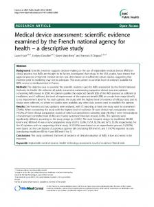
A rod clamped in a rotatable, vertical vise forms the basis of a sturdy, inexpensive, and convenient bite-board holder for vision research. Bite boards made with a hard, dental impression wax are widely employed to steady the observer's eye in Maxwellian-view optical systems (Boynton, 1966). Due to individual differences in facial features, jaw structure, and preferred eye, the bite board must be adjustable with respect to the optical exit pupil. The bite board is usually positioned while viewing the stimulus and then rigidly locked into place. This can be accomplished by a machine-tool-type device such as Gaertner Scientific's R287 XYZ positioner that provides translation along three axes, but at considerable expense: $590. Such commercial positioners are also bulky, and they do not provide rotary adjustments that can be important in obtaining a comfortable viewing position. The bite-board holder described in this paper accommodates both rotation and translation along three axes. The unit can be set using only two controls, and it is rigid and simple to build. Many years of demanding use have proved this design to be satisfactory. Basically, the device involves a rod clamped in a rotatable vise (see Figure 1). The clamped rod is 12 em long and 2.5 cm in diameter and is made of solid, machine-grade aluminum (6062 T6) stock. Choice of rod length involves a tradeoff between the amount of adjustable displacement vs. space constraints and moment of motion. Some softness of rod material is desirable for good clamping, yet permanent deformation must be avoided. One end of the rod is machined flat and provided with a bolt for fastening the bite board. A heavy-duty ball-and-socket camera tripod head can also be fastened to the rod to hold the bite board. The ball and socket facilitates fine positioning and has been sufficiently sturdy for most applications. The illustrated vise was made from a solid 13 x 3.8 x 3.8 em bar of cold-rolled, mild steel by milling a 2.5-cm slot along its center for 10.5 ern of its length. When lacking a milling machine, I have also bolted two 13 x
Figure 1. Illustration of the bite-board holder described in this paper. 2.5 x .6 em brass bars to either side of a 2.5-cm cube of iron. The material for the jaws must undergo some flex without permanent bending. The vise is tightened by means of a transverse rod threaded through the jaws. When the jaws are made of a stiffer material, such as brass, the tightener can be placed in the middle of the jaws with the rod clamped above it, a somewhat more compact arrangement. The vise rests on the horizontal surface of a 25-cm-long piece of 7.6 x 7.6 x .6 cm angle iron. This surface has an I8-cm-Iong slot that permits a handle threaded to the base of the vise to fasten the vise at various horizontal positions. The vertical face of the angle iron is attached to an optical table (Nilsson, 1979) so that the center of the jaws is located approximately 19 cm below and 5 em behind the artificial pupil. REFERENCES
BOYNTON, R. M. Vision. In J. B. Sidowski (Ed.), Experimental methods and instrumentation in psychology. New York: McGraw-Hill, 1966. NILSSON, T. H. Sturdy, inexpensive optical table. Applied Optics, 1979,II, 7S3.
The author thanks P. De Groot for technical assistance.
(Accepted for publication December 7, 1982.)
106
Copyright 1983 Psychonomic Society, Inc.