Nov 20, 2008 - Korea Aerospace University, Korea. Summary ... study proposes to use particle swarm optimization, which is motivated from the simulation of ... It can carry out complex and sophisticated self organization with no clear leader.
302
IJCSNS International Journal of Computer Science and Network Security, VOL.8 No.11, November 2008
Obstacle Avoidance Algorithm for Collective Movement in Nanorobots Khin Haymar Saw Hla, YoungSik Choi and Jong Sou Park Department of Computer Engineering Korea Aerospace University, Korea Summary Recent advances in nano technology lead to nanorobots, which are effectively used as nanomedicine. Future medical nanotechnology has been imagined to employ nanorobots injected into the human body to perform treatment on a cellular level. Every nanorobot placed inside the human body will encounter immune system as obstacles during flowing within a human body. Thus nanorobot must use strategy for avoiding and escaping from such immune system. To avoid obstacles during movement trajectory, self organized trajectory planning is required. This study proposes to use particle swarm optimization, which is motivated from the simulation of social behavior of natural species, as a feasible approach for self organized control of nano scale robots to avoid obstacle throughout the movement trajectory. The simulation analysis has shown that self organized control over throughout the movement can be achieved by using proposed approach.
Keywords: particle swarm optimization, coverage, nanorobots, nanomedicine, obstacles avoidance
1. Introduction The nanoscale science is becoming a challenging area in the sense of building biomolecular scale devices. Nano engineering advances permit programmable and controllable nano scale robots, called nanorobots, which are used to convey information about the microscopic world. Nanorobots are designed to perform a specific task with precision at nanoscale dimensions, which can work inside the human body. It provides many novel capabilities through their ability to sense and act in microscopic environments. In the near future, nanoscale technology will allow the production and deployment of nanorobots and used for investigating within human body. The spatially distributed nanorobots can collect important information about the target environment by moving throughout the human body. Though nanorobots have not yet been able to produce, theoretical studies identify their possible sort of capabilities in nanomedicine. Medicinal uses of nanorobots involve the possible of accurately identify particular cells or places in the human body. Nanorobots would first be injected into a human body and would then go to work in a specific organ or tissue mass. They may be able to detect macroscopic variations and communicate these changes to other nanoproducts working within the body. Chemical Manuscript received November 5, 2008 Manuscript revised November 20, 2008
recognition is used to find out the target within human body. The target has surface chemicals that allow the nanorobots to detect and recognize it. By measuring changes in volume, concentration, displacement and velocity, pressure, or temperature of cells in a body, nanorobots may be able to distinguish between and recognize certain cells [3, 4, 5, 7]. Many attempts have been tried to claim about the possible use of programmable and controllable nanorobots for medicine. The use of artificial intelligence as an appropriate means to enable some aspects of intelligent behavior in the control of nanorobots has been discussed in the nano community [5]. However, developing intelligent control systems to perform specific tasks in nanorobots and algorithms to work in lack of global information and constrained environment has been still challenging. The use of concepts derived from collective robotics and behavior based natural systems were investigated to solve these problems. Self organizing and emergence behavior of behavior based natural systems give rise to intelligent control strategy that can carry out complex and sophisticated global behavior. The behavior based intelligences are motivated by natural species and can show great adaptability and robustness with relatively simple algorithms, as well as low computation cost. Swarm Intelligence system is behavior based control systems, typically made up of a population of simple components interacting locally with one another and with their environment [10]. The components follow very simple rules. Although there is no centralized control structure dictating how individual components should behave, local interactions between such components lead to the emergence of complex global behavior. It can carry out complex and sophisticated self organization with no clear leader. In self organization process, structure and functionality at the global level of a system emerge solely from numerous interactions among the lower level components of the system without any external or centralized control. Emergent behavior of a system is provided by the apparently meaningful collaboration of components individuals in order to show capabilities of the overall system far beyond the capabilities of the single components.
IJCSNS International Journal of Computer Science and Network Security, VOL.8 No.11, November 2008 Particle swarm optimization (PSO), which is motivated from the simulation of social behavior of natural species, is a swarm intelligence base algorithm that used to find a solution to an optimization problem in a search space. PSO models the set of potential problem solutions as a swarm of particles moving around in a virtual search space by adapting self organizing concept. The modeling of natural species by means of self organizing can help design of decentralized control for nano scale devices. In this study, we focus collective movement control of nanorobots throughout investigating within human body. Movement of nanorobots is carried out in self organized way by applying Particle Swarm Optimization algorithm. Along with the self organized behavior, obstacle avoidance is also considered to get the complete control strategy during movement trajectory. Obstacles should be avoided intelligently when a nanorobot has been placed within human body. There have been some proposed solutions for obstacles avoidance with PSO. Hao et al. [9] proposed real time obstacle avoidance method based on polar coordination particle swarm optimization method for robot path planning in dynamic environment. They proved the feasibility of the method in dynamic environment. In this study, polar coordination based particle swarm optimization search based on the environment of the nanorobots is proposed. The motivation for such study is the fact that new approaches for better control of nanorobots can have a great impact on effective development of nanomedicine. The rest of the paper is organized as follows: Section 2 introduces the architecture of a nanorobot. Section 3 discusses the detailed algorithm of proposed approach along with obstacle avoidance. Section 4 presents about simulation scenario, the performance results and discusses how proposed control algorithm effectively worked. Finally, section 5 outlines the conclusions and future work.
2. Nanorobot’s Architecture A nanorobot is a kind of molecular machine, which includes embedded and integrated devices that can comprise the main sensing, actuation, data transmission, remote control uploading, and coupling power supply subsystems. They also have specific sensory capabilities to detect the target regions, obstacles and chemicals relevant for their applications. An actuator, which contains biologically based components, has been proposed to use as mechanical devices to pump fluid, open and close valves or to provide translational movement. To control the nanorobot’s position, transponder device, which can track object in a space, is mainly used. Transponder has one or more transponder antennas through which a transponder circuit receives a RF signal. Nanoscale semiconductor, such as a complementary metal oxide semiconductor (CMOS) is used as a part of
303
circuit assembly. Carbon nanotubes (CNT) and deoxyribonucleic acid (DNA) are combined to create new genetically programmed self assembling materials for facilitating the selection placement of CNTs on a substrate by functionalizing CNTs with DNA. CNTs are able to improve performance with low power consumption for nanosensors. DNA can be used for coupling energy transfer and proteins may serve as basis for ionic flux with electrical discharge. An array format based on CNTs and CMOS techniques could be used to achieve nanomanipulators as an embedded system for integrating the future architecture of molecular machine. The nanorobot uses sensors allowing it to detect and identify nearby objects in the environment or its target region. Biosensors are used to incorporate living components that can be used to monitor the presence or a level of a molecule in a physiological fluid. Chemical sensors can be useful for nanorobot target identification and actuation in investigating within human body. Siliconbased chemical and motion sensor arrays using two-level architecture hierarchy has been successfully conducted since 15 years ago. CMOS based sensors with nanowires can achieve maximal efficiency for chemical changes. Sensors with suspended arrays of nanowires assembled into silicon circuits can drastically decrease self heating and thermal coupling for CMOS functionality. Temperature sensors can be useful for nanorobot, to diagnose, as well as to collect data in patient monitoring. CMOS as a thermoelectric sensor has the advantage of self generated response with system integration without requiring temperature stabilization. The hardware architecture for a nanorobot must include the necessary devices for monitoring the operational workspace such as a human body. In this manner, data processing, energy supply, and data transmission capabilities should be addressed through embedded integrated circuits. The use of VHDL (very high speed integrated circuit hardware description language) has become the most common methodology. By using these devices, one can achieve nanometer scale spatial resolution and provide accurate real time information. Energy is one of the important factors to the nanorobot while it is performing predefined tasks in the environment. A low frequency energy source can be sufficient to operate nanorobots. Kinetic energy can be generated from the bloodstream due to motion interaction with designed devices embedded with the nanorobot. Most recently, remote inductive powering has been used to supply power on the order of milliwatts. One of the practical way is to obtain both energy and data transfer capabilities by using mobile phone. The mobile phone should be uploaded with the control software that includes the communication and energy transfer protocol. For communication in liquid workspace, acoustic, light, RF and chemical signals can be considered as possible choices
304
IJCSNS International Journal of Computer Science and Network Security, VOL.8 No.11, November 2008
for communication and data transmission. Chemical signaling and sensor based behavior are quite suitable for nearby communication among nanorobots for some cooperation work. Acoustic communication is more appropriate for long distance communication and detection with low energy consumption. Although optical communication permits faster rates of data transmission, its energy consumption is higher comparing with others. For data transferring, 4.5 kHz frequency with approximate 22μs delays is possible ranges. Frequency ranging from 1 to 20 MHz can be successfully used for biomedical applications. Recently, mobile phones are more widely accepted than RF CMOS transponders and can be useful as sensors for acquiring wireless data transmission from nanorobots injected inside the human body [3].
3. Collective Movement in Nanorobots One important aspect of nano scale robots and its application in medicine is the development of control automation algorithms for their movement trajectory. Three behavioral control techniques have been considered to control the nanorobots’ motions. First approach used nanorobots’ small Brownian motions to find the target by random search. In second approach, nanorobot monitors for chemical concentration intensity for E-cadherin signals. After detecting the signal, the nanorobot estimates the concentration gradient and moves toward higher concentrations until it reaches the target. In third approach, nanorobots at the target release another chemical, which others use as an additional guiding signal to find the target [5]. In these approaches, the nanorobots are spread across an arbitrary manner. It is difficult to obtain the optimized monitoring by applying randomize approach rather intelligent way should be incorporated. In this paper, the particle swarm optimization algorithm (PSO) is proposed as an appropriate control algorithm to control nanorobots’ mobility within a human body. Obstacles avoidance is also considered to achieve the complete control strategy.
3.1. Obstacle Avoidance One of the major aspects in the movement control of a nanorobot is obstacles avoidance. Every nanorobot placed inside the human body will encounter immune system as obstacles during flowing within a human body. Thus nanorobot must use strategy for avoiding and escaping from such immune system. The nanorobot equips with sensors to detect obstacles and identifies when it has encountered. To avoid obstacles during trajectory, self organized trajectory planning is required. Even though obstacles can be all shapes and sizes, circle representation is considered here for the simplicity. The structure of obstacles can be defined as follows.
Obstacle =< Pcenter , Pradium , Pvelocity >
(1)
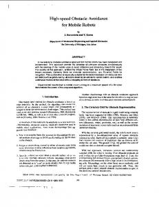
Here, Pcenter, Pradium and Pvelocity are the center point, the radium and the velocity of the moving obstacle. Polar coordinate system, which is the two dimensional coordinate system in which points on a plane is determined by an angle and a distance, is used to find out the trajectory for obstacle avoidance. It can be used effectively for computing the desirable direction angle for movement trajectory of nanorobot. Each obstacle can be represented in polar coordination by following equation: r 2 − 2rri cos(θ − θi ) + ri2 − r 2 = 0 (2) In which, r is radium of obstacle and (ri, θi) is the center of the obstacle. The nanorobot will detect dynamic obstacles at real-time and get obstacles information and then determine the movement trajectory. Obstacle
r
y
Pcenter
Δθj Δθi si
Nanorobot
θ0 x
Fig 1. Obstacle in polar coordination
When a nanorobot moves, it will detect moving obstacle on a certain distance according to time Δt. Suppose an obstacle has a certain position (xi,yi) and both obstacle and nanorobot move with the same fluid velocity vf (vfxi,vfyi), the new position of obstacle (xj,yj) within time Δt can be calculated as follows: (3) x j = xi + v f xi ∗ Δt ; y j = yi + v f yi ∗ Δt The distance Δd between a nanorobot and the center of the obstacle, Pcenter within time Δt can be calculated by using the following equation. Δd = ( x j + v f x j ∗ Δt − xi + v f xi ∗ Δt ) 2 + ( y j + v f x j ∗ Δt − yi + v f yi ∗ Δt ) 2
(4) Prediction on the obstacle’s movement in a dynamic unknown environment is one of the important factors to avoid the obstacles effectively. The time to collision Δtc can be figured out based on Δd, the distance between the obstacle and the nanorobot. Based on the collision time Δtc, nanorobot can predict the obstacle’s future position and adjust the movement trajectory. Time to collision Δtc can be calculated as follows:
IJCSNS International Journal of Computer Science and Network Security, VOL.8 No.11, November 2008 2 * (−xi ∗ v f xi − yi ∗ v f yi + v f xi ∗ x j + v f yi ∗ y j + xi ∗ v f x j − x j ∗ v f x j + y i ∗ v f y j − y j∗ v f y j ) (−2 * (− xi ∗ v f xi − yi ∗ v f yi + v f xi ∗ x j + v f yi ∗ y j + xi ∗ v f x j −
Δt c =
− x j ∗ v f x j + yi ∗ v f y j − y j∗v f y j )) 2 − 4 ∗ (v f xi2 + v f yi2 − 2v f xi ∗ v f x j + v f x 2j − 2 ∗ v f yi ∗ v f y j + v f y 2j ) * ( xi2 + yi2 − xi2 − 2 ∗ xi ∗ x j + x 2j − 2 ∗ yi ∗ y j + y 2j − 2 ∗ ri * r j − r j2 )
(5)
2 * (− xi ∗ v f xi − yi ∗ v f yi + v f xi ∗ x j + v f yi ∗ y j + xi ∗ v f x j − x j ∗ v f x j + yi ∗ v f y j − y j∗v f y j )
When an obstacle is encountered (figure 1), the heading of nanorobot can be adjusted to the Δθj radium, which can be represented as follows: Δθ j = arctan
Here, r is radium distance between a trajectory of the transforming Polar follows:
r d ( s i , Pcenter )
(6)
of the Obstacle; d (si, Pcenter) is the nanorobot and an obstacle. Then, the nanorobot can be calculated by coordinate to Cartesian coordinate as
x = r * cos(Δθi ) ; y = r * sin(Δθi )
(7)
3.2. The Formulation of Optimization Model Movement of a nanorobot’s position is realized by the Particle Swarm Optimization (PSO) algorithm. PSO converges to the best solution by adjusting the trail of each individual particle towards its own best location based on the best of itself and the global best based on the neighbor particles. In this case, each particle becomes a nanorobot. The modification of a nanorobot’s position is realized by position and velocity information. The position of each nanorobot is represented by Cartesian coordinate, such as x, y axis position and the velocity is modified by PSO. The inertial force, viscosity of the fluid for a nanorobot is impact on the new positions. The ratio of inertial to viscous forces for a nanorobot moving through a fluid is measured by Reynolds number R, which gives a measure of the ratio of inertial forces (vf) to viscous forces (η) and, consequently, it quantifies the relative importance of these two types of forces for given flow condition. It provides a measure of turbulence or laminar flow characteristics of fluid flow around moving nanorobots. Reynolds number R with viscosity, represented by η velocity, represented by vf and density, represented by δ is given as follows: (8) R= δvf / η The initial position for the nanorobots is initialized with random coordinates. Initial velocities are found out based on fluid forces measured by Reynolds number R that dominates through the fluid in the human body. Due to the viscous forces, the nanorobots flow to a new location. Each nanorobot is defined within the context of a topological neighborhood comprising itself and some other nanorobots
305
in the population. Neighbors of each nanorobot can be carried out based on the distance of nanorobot’s position. In this study, global path and local path are considered for nanorobot’s movment path planning. Global path is carried out based on the globally fitness function. Globally fitness value is evaluated for each nanorobot over its neighborhoods based on the coverage of the target area. When a particle or a nanorobot discovers a pattern that is better than any it has found previously, it stores the coordinate as new best position. The stochastically difference between the neighborhood’s best position and individual’s current position is also added to its velocity, adjusting it for the next time step and finally, the new best positions of the nanorobots are carried out. When obstacles are encountered, the local path planning is found out for obstacle avoidance. Collision free positions are carried out based on the poloar coordinate based obstacle avoidance algorithm. Global Path Global path is carried out based on the coverage of the particles, which reflects how well a nanorobot is monitored to the target area. Suppose there are two nanorobots si and sj located in positions (xi,yi) and (xj,yj) with sensing ranges ri and rj respectively. Without loss of generality, movement of nanorobot will be addressed how target area is perimeter covered by both nanorobots si and sj. We can say that a point on the si is perimeter covered by sj if and only if si is within the sensing range of sj. Sensing range is a circular disk centered at the node, whose radius is termed as the sensing radius of the node. Let Di be the coverage area for node i. Di is the π r2 if the nanorobot’s sensory region is properly contained in the deployment area. Let Ti denotes the total coverage for deployment area. For all nanorobots si, where 0≤ i ≤ n, we will find out the expected value over total coverage area T. Let A is the area of the perimeter covered by nanorobots after i nodes have been randomly placed. Let Aij be the area of perimeter covered by si over sj. Aij can be calculated as follows: A = 2[
r2 (θ − sin θ)] 2
(9)
Where, r represents the sensing radius of nanorobot si and θ represents the angle of the arch falling by nanorobot si over sj. Let Ki be the area of the segment, falling outside of the target area T. Ki can be calculated as follows: (10) K = r 2 [θ − sin θ] 2 The expected value of total area covered can be calculated as follows: n ⎡ ⎤ Di − ⎢ Ai j + Km ⎥ ⎢ ⎥ i =1 m =1 ⎣ i, j ⎦ E[ Di j ] = Ti n
∑
∑
∑
(11)
306
IJCSNS International Journal of Computer Science and Network Security, VOL.8 No.11, November 2008
In which, Di represents the coverage of ith nanorobot. Expected value is found out after deducting overlap area Aij and Ki, area of the segment falling outside of the target area T from total coverage D. The goodness of the position can be computed by using the objective function, which is denoted by the fitness function. Fitness value is found out based on the coverage of the neighborhoods. Let the best fitness value obtained by a nanorobot at a selected time is Fi=[fi1, fi2,…..,fik]T, and the global fitness value of a swarm of neighbor nanorobots at the selected time is Fg=[fg1,fg2,…,fgk]T. The utility function ui finds out the maximum coverage area over target region T as follows: F (ui ) = E[ Di j ] (12) Let ug be the utility function that finds out the global fitness value of neighbors of nanorobot si, ug finds out the maximum coverage area over fitness of the neighbors of nanorobot si. Globally fitness function at kth iteration is represented as follows: (13) Fg ( k ) = arg max u g ( Fi ( N ( si ( k )))) In which, N(si) is the set of neighbors of nanorobot si and Fi(N(si)), is the fitness function that finds the fitness value over the neighbors of nanorobot si. We can say that nanorobot sj is a neighbor of si if and only if the Euclidean distance between si and sj is ≤ 1, which can be defined as follows: (14) N ( si ) = {s j ∈ S d ( si , s j ) ≤ 1, si ≠ s j } Suppose that the position change vector, velocity of the ith nanorobot at a selected time is Vi=[vi1,vi2,…..,vik]T. The velocity of each nanorobot si in the kth iteration can be modified by the following equation. vi(k+1)= R+ vi(k) + w1 (fi (k)-si (k)) + w2 (fg (k)-si (k)) (15) Where R is Reynolds number, which is inertia force of the fluid, w1 and w2 are uniformly distributed random numbers in the range [0,1], which are the weighting factors that say how much a nanorobot is directed towards good position, vi(k) and si(k) represent the velocity and the position of the nanorobot si at instant k. When the velocity is updated in the kth iteration, the velocity v of the nanorobot decides where it moves next by using the following equation. (16) si (k+1)=si (k)+vi( k+1 ) Local Path Local path for each nanorobot is found out when obstacles are encountered. By comparing distance between each nanorobot over obstacle, the position and velocity are adjusted and fitness function is evaluated with the new coordinate. Distance between nanorobot and obstacle can be calculated by using Euclidean distance function. The goodness of the position can be computed by using the fitness function Fj. Fj is computed based on the obstacle free coordinates of the nanorobot. Let {T} be the set of
target region represented by [T0, ⊗Tobstacle] that contains target points and some obstacles. Let uj be the utility function that finds out the fitness of the each nanorobot si within target area T that is it finds out the obstacle free position of nanorobot si over the target region T. Fitness function for each nanorobot at kth iteration is represented as follows: F j (k ) = arg maxu j ( si si ∈ S , si ∉ Tobstacle ) (17)
3.3. Movement Control Algorithm The nanorobot must use control algorithms involving movement around the environment of the search space to identify and monitor the targets. The algorithms mainly considered here are that of movement control algorithm. The Movement Control Algorithm 1) As the nanorobot moves through the search space gaining one new position based on fluid velocity, the conditional statement checks if it has enough coverage based on its neighbors. 2) To be a neighbor, for each nanorobot si,sj∈S, where i,j=1..n checks for the distance information whether the Euclidean distance between si and sj ≤ 1. 3) For each nanorobot si, calculate the coverage value based on the neighbor nanorobots. 4) If coverage value < threshold value, it will find out the new position again. 5) The new position is selected randomly, then the neighbors are found out based on the new position and coverage over the new position is carried out. 6) The fitness function is evaluated over the new position based on the coverage over current position and coverage over global best position. 7) If the best position is found out, update the velocity and move to the next location. 8) When a nanorobot detects an obstacle, it can predict the future position of obstacle due to the distance between two moving objects, Δd and time taken on movement Δt. 9) The obstacle’s moving distance Δd in time Δt influences the time to collision Δtc. 10) When nanorobot steps into a new location, it checks if there are dynamic obstacles in current target area. 11) If this condition is true, the obstacle avoidance algorithm is initiated. 12) Time to collision Δtc is found out to predict the next position of the obstacle. 13) Based on the Δtc, nanorobot is headed to the collision free position Δθi and move to the new location. 14) The position of the nanorobot is changed and fitness over current position is checked again. 15) If fitness is less than threshold value, new position is carried out.
IJCSNS International Journal of Computer Science and Network Security, VOL.8 No.11, November 2008 16) If no dynamic obstacles in current target area, nanorobot goes ahead along with global path. The detailed algorithm for obstacle avoidance is shown in figure (2) as follows:
307
will change its position based on the global path accordingly so that the new position information is broadcasted to the others.
4.2. Simulation Setup Algorithm Obstacle Avoidance Begin 1. Calculate Δd, distance between nanorobot si and obstacle 2. Calculate time to collision Δtc based on Δd 3. Start to generate Δθij, based on Δtc 4. Calculate Cartesian coordinate’s xij,yij from polar coordinates where xij is r*Cos(Δθij); yij is r* Sin(Δθij); r is the radius of the obstacle (0< Δθijcurrent optimum 8. Current optimum target=current selected target 9. Move nanorobot si to new best position 10.End if End Fig 2. Obstacle avoidance algorithm
4. Simulation and Discussion We have studied the performance and behavior of our system in simulation to demonstrate the potential of our algorithms.
4.1. Simulation Scenario Simulation scenario considered here is that nanorobot operating in finding target information in blood vessels. The fluid in the vessels contains red blood cells and tumor cells. To find out the target, nanorobot uses the chemical recognition of the background concentration. If no signal was detected, a nanorobot just keeps flowing with the bloodstream to avoid spending power in unnecessary active locomotion. When a nanorobot detects the higher concentration signal of the target, it releases another signal to attract other nanorobots. A nanorobot can estimate the number of nanorobots at the area by monitoring the concentration of a signal from others. It stops attracting others when the target region has enough coverage. These nanorobots are positioned according to the coverage of the target area. Then nanorobots move throughout the target area by detecting higher signal concentration. For the movement of a nanorobot, viscosity dominates through the fluid in the body. Due to the viscous forces, the nanorobots flow to the new location. The movement process consists of alternate short movements with random changes in direction. Whenever obstacles are identified, the nanorobots place to the new obstacle free positions based on the local path. After obstacle is avoided, each nanorobot
We perform the analysis to the methods brought forward above. In order to analyze the effectiveness of movement control algorithms, several simulation parameters shown in table 1 are used. Some tests are carried out to illustrate the proposed algorithm in following the environments well. The algorithms were implemented in a Java programming environment. In the simulation experiment, for the sake of convenience, the following assumptions are used. 1) Both nanorobot and obstacle flow with same fluid velocity. 2) Nanorobot and obstacle has same radium. Table 1. Parameters
Parameter
Value
No. of nanorobot Size of nanorobot si Radius of sensing range ri Fluid velocity vf Vessel diameter Density δ Viscosity η Fitness threshold ε
10 1 μm 3μm 100 μm /s 20 μm 1 g/cm3 10-2 g/cm.s 0.1 < ε ≤ 0.9
4.3. Simulation Experiments In order to examine the performance of the proposed obstacle avoidance algorithm, we use random obstacles in dynamic environment. We consider for the moving obstacles and moving nodes. The algorithm is used to navigate circular shape obstacles. Runtime requirement for the algorithm is 0.024 second for a trial. Figure 3 depicts the illustration representation of obstacle avoidance of 10 nanorobots, which is based on the global path planning and local path planning. When there are no obstacles, nanorobots move to the new position based on global path planning. When obstacles are encountered, by adjusting between time to collision Δtc, and runtime of the algorithm, the nanorobot can turn its heading suddenly to escape the collision. When nanorobots identify an obstacle, they invoke obstacle avoidance algorithm and find out Δθi, radium to be headed (figure 3(a), (b)). Then, they move to the collision free coordinates, which is calculated based on the Δθi (represented in equation (6)), (figure 3(b), (c), (d)). After crossing over the obstacle, the nanorobots place their positions due to the coverage of the target environment (figure 3 (e)), which is based on the global path planning. In this illustration, we can clearly see that whenever the obstacles are encountered, the new obstacle free positions can be set up efficiently.
IJCSNS International Journal of Computer Science and Network Security, VOL.8 No.11, November 2008
308
5. Conclusions and Future Work
3 2.5
Realizing applications of nanorobots to health issues raises new control challenges. The intelligent control systems for nanorobots may great impact on the development of future medical nanorobotic systems. This study has investigated the possibility of using nanorobots to investigating within human body. The polar coordinate system based Particle Swarm Optimization approach has been proposed as a feasible approach for the self organized control of nano scale robots. Obstacles and possible collisions can be avoided while still continuing on an efficient trajectory, leading towards convergence on the target. The simulation results have approved that the proposed scheme effectively constructs an obstacle free self-organized trajectory. Our future work will be addressed the current issue in 3D virtual reality environment at the nanoscale level.
y position
2 1.5 1 0.5 0 0
0.5
1
1.5
2
2.5
3
3.5
4
4.5
2.5
3
3.5
4
4.5
x position
(a) 3 2.5
1 0.5 0 0
0.5
1
1.5
2
x position
(b)
Acknowledgements
3
This research was supported by the Advanced Broadcasting Media Technology Research Center (ABRC) in Korea Aerospace University, Korea, under the Gyeonggi Regional Research Center (GRRC) support program supervised by Gyeonggi Province.
2.5
y position
2 1.5 1 0.5 0 0
0.5
1
1.5
2
2.5
3
3.5
4
4.5
References
x position
(c) 3 2.5
y position
2 1.5 1 0.5 0 0
0.5
1
1.5
2
2.5
3
3.5
4
4.5
3
3.5
4
4.5
x position
(d) 3 2.5 2 y position
y position
2 1.5
1.5 1 0.5 0 0
0.5
1
1.5
2
2.5 x position
(e) Obstacle
Nanorobot faced with obstacle
Collision free nanorobot
Fig 3. Obstacle avoidance of 10 nanorobots
[1] A. Aristides, G. Requicha, “Nanorobots, NEMS and Nanoassembly.”, Proceedings of the IEEE, 2003, pp. 1922– 1933. [2] A. Casal, T. Hogg and A. Cavalcanti, “Nanorobots as Cellular Assistants in Inflammatory Responses”, IEEE BCATS Biomedical Computation at Stanford 2003 Symposium, IEEE Computer Society, Stanford CA, October 2003. [3] A. Cavalcanti, B. Shirinzadeh, R. A. Freitas Jr. and T. Hogg, “Nanorobot Architecture for Medical Target Identification”, Nanotechnology Electronic Journal, volume 19, No. 1, January, 2007. [4] A. Cavalcanti, L. Rosen, B. Shirinzadeh and M. Rosenfeld, “ Nanorobot for Treatment of Patients with Artery Occlusion”, Proceedings of the Virtual Concept 2006, Mexico, 2006. [5]A. Cavalcanti, R. A. Freitas Jr. and L. C. Kretly, “Nanorobotics Control Design: A Practical Approach Tutorial”, Proceedings of the ASME Design Engineering Technical Conference, 28th Biennial Mechanisms and Robotics Conference, Salt Lake City, USA, 2004. [6] A. Cavalcanti, “Assembly Automation with Evolutionary Nanorobots and Sensor-Based Control Applied to Nanomedicine”, IEEE Transactions on Nanotechnology, 2(2), June 2003, pp. 82-87. [7] A. Cavalcanti, T. Hogg, B. Shirinzadeh, H. C. Liaw, “Nanorobot Communication Techniques: A Comprehensive Tutorial”, Proceedings of the IEEE ICARCV 2006 International Conference on Control, Automation, Robotics and Vision, 2006. [8] A. Galstyan, T. Hogg, K. Lerman, "Modeling and Mathematical Analysis of Swarms of Microscopic Robots",
IJCSNS International Journal of Computer Science and Network Security, VOL.8 No.11, November 2008 IEEE Swarm Intelligence Symposium, Pasadena CA, USA, June 2005, pp. 201-208. [9] Y. Hao, W. Zu, Y. Zhao, “Real-Time Obstacle Avoidance Method based on Polar Coordination Particle Swarm Optimization in Dynamic Environment”, Proceedings of the 2nd IEEE Conference on Industrial Electronics and Applications, China, May 2007, pp.1612-1617. [10]J. Kennedy, and R. Eberhart. “Swarm Intelligence”. Morgan Kaufmann, CA, 2001. [11]C. Montemagno and G. Bachand, “Constructing Nanomechanical Devices Powered by Biomolecular Motors”, Nanotechnology, 1999, pp 225–231. [12] V. Shanthi and S. Musunuri, “Prospects for Medical Robots”, AZo Journal, September, 2007. [13] L. L. Smith, G. K. Venayagamoorthy, P.G. Holloway, “Obstacle Avoidance in Collective Robotic Search Using Particle Swarm Optimization”, In Proceedings of the IEEE Swarm Intelligence Symposium, 2006, Indiana, USA, 2006. [14] H. Yamamoto, S. Uemura, Y. Tomoda, S. Fujimoto, T. Hashimoto, K.Okuchi, “Transcardiac Gradient of Soluble Adhesion Molecules Predicts Progression of Coronary Artery Disease”, International Journal of Cardiology 84, 2002, pp. 249-257. [15] S. Zhou, M. Wu and W. Shu, “Finding Optimal Placements for Mobile Sensors: Wireless Sensor Network Topology Adjustment”, Proceedings of the IEEE 6th Circuits and Systems Symposium on Emerging Technologies, Shanghai, China, May, 2004.
Khin Haymar Saw Hla is currently postdoctoral researcher at Korea Aerospace University, Korea. Her current research interest focuses on wireless sensor network, embedded system, multi agent systems and swarm intelligence.
YoungSik Choi received the BS and MS degrees in electronics from Yonsei University, Seoul, Korea, in 1985 and 1987, respectively, and the PhD degree in computer engineering from the University of Missouri, Columbia, in 1996. From 1988 to 1991, he was with the Research Center, Korea Telecom. From 1996 to 2001, he was a senior researcher in the Multimedia Technology Research Laboratory, Korea Telecom. He is currently an associate professor in the Department of Computer Engineering, Korea Aerospace University, Korea. His research encompasses many aspects of pattern recognition, information retrieval, and data mining. His current research interests include image and video retrieval, internet search engine, and Web data mining.
309
Jong Sou Park received the M.S. degree in Electrical and Computer Engineering from North Carolina State University in 1986. And he received his Ph.D in Computer Engineering from The Pennsylvania State University in 1994. From 1994 - 1996, he worked as an assistant Professor at The Pennsylvania State University in Computer Engineering Department and he was president of the KSEA Central PA, Chapter. He is currently a professor in Computer Engineering Department, Korea Aerospace University. His main research interests are information security, embedded system and hardware design. He is a member of IEEE and IEICE and he is an executive board member of the Korea Institute of Information Security and Cryptology and Korea Information Assurance Society.