Further, it is difficult to accurately and rapidly detect and measure defects, ... Studies have demonstrated that the use of external or internal defect data ... thick x 6 inches wide x n feet long (2x6's), etc. ... along with its defects. .... If the desired image is to be 750 pixels wide, the scaling factor would be 750 /(2 .... J. 48(1):72-75.
PROCEEDINGS OF SPIE REPRINT SPIE-The International Society for Optical Engineering
Primary detection of hardwood log defects using laser surface scanning E. Thomas, L. Thomas, L. Mili, R. W. Ehrich, A. L. Abbott, C. Shaffer
Reprinted from Machine Vision Applications in Industrial Inspection XI 22-24 January 2003 Santa Clara, California, USA
Volume 5011
© 2003 by the Society of Photo-Optical Instrumentation Engineers P.O. Box 10, Bellingham, Washington 98227 USA. Telephone 360/676-3290.
Primary Detection of Hardwood Log Defects Using Laser Surface Scanning Ed Thomasa, Liya Thomasb, Lamine Millc, Roger Ehrichb, A. Lynn AbboUc, Clifford Shafferb a
Northeastern Research Station, USDA Forest Service, 241 Mercer Springs Road, Princeton, WV 24740 b Department of Computer Science, Virginia Polytechnic Institute and State University, Blacksburg, VA 24061 c Bradley Department of Electrical Engineering, Virginia Polytechnic Institute and State University, Blacksburg, VA 24061 ABSTRACT The use of laser technology to scan hardwood log surfaces for defects holds great promise for improving processing efficiency and the value and volume of lumber produced. External and internal defect detection to optimize hardwood log and lumber processing is one of the top four technological needs in the nation's hardwood industry. The location, type, and severity of defects on hardwood logs are the key indicators of log quality and value. These visual cues provide information about internal log characteristics and products for which the log is suitable. We scanned 162 logs with a high-resolution industrial four-head laser surface scanner. The resulting data sets contain hundreds of thousands of three-dimensional coordinate points. The size of the data and noise presented special problems during processing. Robust regression models were used to fit geometric shapes to the data. The estimated orthogonal distances between the fitted model and the log surface are converted to a two-dimensional image to facilitate defect detection. Using robust regression methods and standard image processing tools we have demonstrated that severe surface defects on hardwood logs can be detected using height and contour analyses of three-dimensional laser scan data. Keywords: laser scanning, wood processing, defect detection, robust estimation, circle fitting
1. INTRODUCTION The last two decades have seen the emergence of various scanning technologies for tree and log processing. Several scanning and optimization systems are available on the market that aid in the sawing of logs into lumber. Defect detection on hardwood trees and logs can be categorized into two areas: internal and external detection. External defect detection refers to the detection of defects on a log's surface. Internal detection is the detection of defects inside logs. Most of the available scanning systems are external models that use a laser-line scanner to collect rough log profile information. These systems were typically developed for softwood (pine, spruce, fir) log processing and for gathering information about external log characteristics such as diameter, taper, curvature, and length!. Once log shape data are obtained, a previously generated cutting pattern or template is selected that best fits the log. Optimization systems then use this profile information to better position the log on the carriage and improve the sawyer's decision-making ability. Adding external defect information to the optimization process is a natural extension of current technology.
Machine Vision Applications in Industrial Inspection XI, Martin A. Hunt, Jeffery R. Price, Editors, Proceedings of SPIE-IS&T Electronic Imaging, SPIE Vol. 5011 (2003) pgs. 39-49 ©2003 SPIE-IS&T. 0277-786X/03/$15.00
This paper considers the use of a four-head laser line scanner for detecting defects on barked hardwood logs. The laser-scanning system used in this research was a commonly available industrial system which generated highresolution profile images of the log surface in three-dimensions. The three-dimensional log surface image is then processed to determine the location of the most severe defects: overgrown knots, rotten knots, holes/gouges, and removed branches. These types of defects usually are associated with a significant surface rise or depression depending on the defect type. The image is processed using a robust statistical approach to fit a series of circles to the log data. By analyzing the radial residuals, which are the estimated orthogonal distances between the fitted circles and the log surface, defects characterized by a height change from the surrounding log area could be located. Traditionally, before a hardwood log is processed an assessment of its quality is performed, typically via a mill operator's visual inspection. This inspection process can be quite subjective depending on the operator. Log quality is inversely proportional to the presence of defects. Log defects include both internal and external defects. In nearly all cases, there is an internal defect located just below an associated surface defect. External defect indicators consist of bumps, splits, holes, and circular distortions in the bark pattern. Bumps usually indicate overgrown knots, branches, or wounds. Some bumps have a cavity or hole in the middle, indicating that the overgrown material has turned rotten. Circular distortions, or rings around a central flattened area indicate a branch that was overgrown many years, or decades ago. Surface defects progress from a pruned branch, pruned naturally or purposefully during management, to an overgrown knot characterized by a significant bump then to a rotten knot or a distortion defect, depending on its circumstances. The difference between high and low quality logs is determined by defect type, frequency, size, and location. Further, it is difficult to accurately and rapidly detect and measure defects, either mechanically or manually. A 10 to 30 percent increase in value was observed by Todorki3 in a study examining sawing strategies for plantation grown radiata pine, in which the external defects were manually located, measured, recorded and entered into the computer. Todoroki estimates that interior scanning, using X-ray/CT or another method, would improve value recovery only an additional 3 percent. Studies have demonstrated that the use of external or internal defect data improves cutting strategies that optimize log recovery or yield, i.e., preserving the largest possible area of clear wood on a board face. The value of the lumber that can be recovered depends on the presence and location of defects. This is especially true for hardwood logs. Softwoods are sawn to fixed stock dimensional sizes, e.g., 2 inches thick x 4 inches wide x n feet long (2x4's) , 2 inches thick x 6 inches wide x n feet long (2x6's), etc. Normally little attention is given to the placement of defects inside or on the log surface in softwood processing. However, in the production of hardwood lumber, boards are sawn to fixed thicknesses and random widths. The presence and placement of defects on the boards are of particular concern as they impact board quality and value. Therefore, much greater attention is given to the presence of the log surface defects during processing. The use of a scanning system to detect log surface defects would improve decision-making when the log is sawn into boards. This can be accomplished with a simple video system that displays the log to be processed along with its defects. The time needed to visually inspect logs would be minimized and enables the sawyer to detect defects that otherwise might be overlooked. While various internal defect inspection methods have been proposed in the literature based on X-ray/CT (Computer Tomography), X-ray tomosynthesis, MRI (magnetic resonance imaging), microwave scanning, ultrasound, and enhanced pattern recognition of regular X-ray images4, 5, 6, 7, no commercial installation of these methods is known to exist at the time of this paper. Using CT data, computer vision algorithms such as the feed-forward artificial neural-network classifier (ANN) developed by Li et a1.8, are able to accurately locate and describe internal log defects. CT or MRI systems provide excellent quality internal images of logs. However, image acquisition is slow and expensive. In addition, the variable moisture content and the size of the log can present problems to the CT scanning device.9 Laser scanners are significantly less expensive and easier to operate than internal log scanning systems. External laser scanning has the potential to significantly improve the volume and value of boards produced. The next section of this paper describes the method we have used for scanning logs, and for estimating a log's shape through a robust circle-fitting procedure. Section 3 presents some results that we have obtained to illustrate the potential of this approach in detecting surface defects. Section 4 contains concluding remarks.
40 Proc. of SPIE Vol. 5011
2. SURFACE SCANNING AND FITTING METHODS A portable laser log scanner by Perceptron, Inc. was used for scanning. The scanner uses four laser-line generator/camera units stationed at 90-degree intervals around the log's circumference. Figure 1 is a schematic of the laser-based log scanner components. The log was held stationary while the carriage holding the four scanning units moved on rails along the log's length. The logs were held in position by supports at 4-foot intervals.
Figure 1. Schematic of the laser log scanner.
2.1. Laser Scanning of the Logs The log scanner can scan a 16-foot long log at low resolution in less than 10 seconds and was designed to collect gross profile information. At low resolution a scan line around the circumference of the log was taken every 4.0 inches. To achieve higher resolution, the speed at which the scanner moves along the log was slowed to approximately 15 feet per minute. At this speed a laser line measurement was recorded approximately every 0.78 inch (Fig. 2). A transducer records the lineal position of the scanner accurate to 0.01 inch. The data set shown in Figure 2 consists of 1,039 threedimensional Cartesian coordinates in single plane. We refer to such a data set as a "slice". Depending on the circumference of the log at any specific location, the number of points in each slice can vary. However, on average the distance between points in each slice of data is 0.04 inch. When a sequence of slices are assembled, a threedimensional map of the log surface is obtained (Fig. 3). During the time the scanner was available, a combination of 162 northern red oak (Quercus rubra) and yellowpoplar (Tulipifera liriodendron) logs were scanned. These are two of the more common and important commercial species in the eastern United States. The sample of logs scanned was obtained directly from the forest and from local sawmills. In general, the logs from the forest were in better condition than those from the sawmills. Due to less handling, the forest logs showed less damage and had fewer and smaller areas of missing bark than the mill logs.
Proc. of SPIE Vol. 5011
41
Figure 2. Single "slice" of data representing the circumference of a log for a single plane.
Figure 3. Representation of three-dimensional data from the laser log scanner.
The first processing step is converting the three-dimensional laser-scanned Cartesian coordinates into a twodimensional, 256-color gray-level image (Fig. 4). In this process, the log surface is unrolled onto a 2D coordinate space. Although this process allows the application of conventional image processing techniques, the high level of noise in the log data makes the conversion difficult. This noise was caused by both the logs and the scanning system, and includes dangling loose bark; duplicate and/or missing data caused by scanner calibration errors; unwanted data from the supporting structure under the log; and missing data due to the blockage of the log by the supporting structure (Fig. 5). In robust statistics, such kinds of noise are called outliers.
42 Proc. of SPIE Vol. 5011
Figure 4. Radial residuals generated by the log-unrolling processing presented as a gray-level image. Light pixels represent protrusions from the log surface, and dark pixels represent depressions. This log is approximately 9 feet in length with a diameter of 21 inches.
Figure 5. Various formations of outliers present in slice data from laser scanning, a: loose bark flakes in lower left comer, b: Outliers in form of scanning support structure and missing data due to structure, c: Outliers and shape of log at one end where the log was cut diagonally instead of squarely, d: A good log data slice containing no outliers.
Proc. of SPIE Vol. 5011 43
2.2. Circle Fitting and Outlier Suppression To convert the 3-D log surface data to 2-D images for processing, a reference surface must be imposed on the slice data from the scanner. Since logs are natural objects and are approximately circular or elliptical along the cross sections, we decided to experiment with fitting circles and ellipses to the slice data, which all together form a reference surface needed for defect detection. It turns out that defects that correspond to rises or depressions in a log's surface can be detected using the contour levels estimated from the orthogonal distances between the fitted reference surface and any point of the slice data. Due to space limitation, we restrict attention to circle fitting, a problem that belongs to nonlinear regression10. To accommodate both model approximations and the possible presence of data points that strongly deviate from the pattern formed by the majority of the measurements, known as outliers, we resort to the theories and methods of robust statistics II. In this application, outliers may stem from either laser -scanner components, loose bark, or extreme protuberant defects. The nonlinear form of the circle equation prompted us to develop a new robust estimation method that is an outgrowth of the one proposed by Mili et al.12. The nonlinear regression model being used for circle fitting is written as (xl - P1 + n1)² + (x2 - p2 + n) - p3 ² + e = 0
(1)
where p = {PI, P2, P3J is the parameter vector containing the center coordinates (PI, P2) and the radius P3 of the circle and where X=[XI, X2J is the two-dimensional measurement vector containing the slide data from the scanner. The uncertainties in the model given by (1) are accounted for by the measurement error vector, 11=[ 17,,17 J, and the model error, e. Consequently, the model (1) can be conveniently written in a compact form as f(p, x + n) + e = 0
(2)
The problem is hence to robustly estimate the parameter vector p in (2) from a set of m two-dimensional data points, {XI, Xz, ... , xm}, provided by the log scanner. The new estimator being developed minimizes an objective function given by
where
m ri J(p) = ∑ wi²ρ ( ), wi i=1
{
1 ri 2 ( wi ) 2 ri ρ ( wi)= ri λ² wi 2
(3) ri for wi < λ ri for wi > λ
(4)
and where ri is the residual associated with the ith measurement (xi1, xi2) defined as ri = - (xi1 - p1)² - (xi2 - p2) + P3² .
(5)
Here, is a breakpoint set equal to 1.5 and wi is an appropriate weight function that downweights the outliers in x and thereby making the estimator robust against them. Unlike the method described in Mili et al.12, the function wi is based on the scaled radial distance between the associated data point xi and the fitted circle. The robust measure of scale of these distances is performed by means of the projection statistics 12,13 while the minimum of (3) is found through the iteratively re-weighted least-squares algorithm12.
44 Proc. of SPIE Vol. 5011
Several log data samples were used to test the robust regression method. The resulting fitted circles vary little among neighboring data slices, which guarantees the smoothness of the fitting over the entire data of one log. Figure 6 shows a circle that was fitted to a data slice of log 480. Outliers in this slice of data identified during processing are plotted in bold. The smoothness of the fitting is further reinforced by smoothing the parameters using a box filter.14 The total number of outliers removed from each log was approximately 3 percent.
Figure 6. Circle fitting of a slice of data from log 480 showing a portion of the log support.
2.3. Creating the Residual Gray-Level Image Using the adjusted, fitted circle for each slice of log data, we can calculate the residuals. The residual values (distances between circle and log surface points) are mapped to a 2-D image using the residual value as a gray-level value and scaled to range from 0 to 255. The log data is not originally in a grid format, so it is interpolated linearly to fill any gaps between data points. The z value (position along the logs length) in the 3-D data is mapped to the 2-D image as the y value. The x value of the image is calculated by scaling the angle of a slice's point from the center of the fitted circle. If the desired image is to be 750 pixels wide, the scaling factor would be 750 /(2 n). On average, the size of an unrolled log output image is about 2 MB and 1,400 x 1,600 pixels. As a result, the resolution of the output gray-level image from log-data unrolling is reduced. The Gaussian pyramid method is applied and a 5x5 window is used to smooth and subsample the image. The image is reduced to 25 percent of the original size, Le., roughly 500 KB/image. This speeds additional analyses of the image with little or no loss of data of interest.
Proc. of SPIE Vol. 5011 45
3. RESULTS AND DISCUSSION Log surface defects are of many types, sizes, and shapes. They can be knots, bumps or bulges, circular distortions, surface rise, splits, etc. Knots include overgrown, adventitious, sound, or unsound (rotten). Distortions can be heavy, medium, or light. Knots can occur in clusters of various numbers and sizes. Most, (approximately 60%), of the severe defect types, (overgrown knots, rotten knots, bumps, sawn off or removed branches, splits, and holes) have a significant height change, either a protrusion or a depression, when compared to the neighboring bark area. Other defects do not change much in terms of height. Some defects are easily identified by color or height characteristics. Others are not very obvious except for their breaking of the natural bark pattern, i.e.: a change in bark texture. In log processing, some types of defects are considered severe, such as knots and heavy distortions, while others are not as serious. Based on these observations the data are processed such that log areas unlikely to contain defects are ignored and removed from the foreground region. Because most severe defects have a localized height change, a height analysis of the residual image provides information about the presence of severe defects. A substantial, localized, and abrupt surface rise or depression greater than 1.0 inch, nearly always is a defect. Since the pixel values in the gray-level image represent radial distances between the fitted circle and the log surface, the analysis is straight-forward. Using the gray-level image, shown earlier in Figure 4, we can generate a contour plot (Fig. 7). In the contour plot image, it is possible to discern the areas containing likely defects based on height information alone. Figure 7 also shows a manually recorded map of the defects on log No. 480. The defect types represented in the map include SKs (sound knots), OKs (overgrown knots), and a gouge. A gouge, a type of hole defect, is an area of missing wood usually caused during felling or poor handling.
Figure 7. Contour plot of log 480's surface with defect locations annotated. 46 Proc. of SPIE Vol. 5011
In areas with a less substantial height change (less than 1.0 inch), the area must be examined more closely. The shape of the defect and the bark texture, if present must be inspected. Defects are normally elliptical in shape with the exception of splits. Thus, an elliptical area with a small rise is likely a defect. When limbs are sawn from a log, the remaining area is raised with an elliptical flattened section in the middle (Fig. 8). These areas are distinctive defect identifiers and potentially can be detected using edge detection methods. In fact, even the pattern left by the chainsaw is evident on the surface and is enhanced by the Canny edge-detection method15 (Fig. 8). Although height data quickly allows us to discriminate between areas with and without severe defects, different processing strategies are required for other defects that are more subtle. Bark distortions are patterns of circular interference in the normally straight lines of the bark pattern. The pattern of a bark distortion defect is similar to that from dropping a stone in water (Fig. 9). These types of defects are formed when a branch stub grows over and indicates a knot below the log's surface. The knot can be just below the surface or several inches below the log surface. This defect is similar to those detected by Tian and Murphy on radiata pine.2,16 They developed a methodology of extracting features and defects from digital photos of logs. Their algorithm determined an orientation field from an image that allowed the circular pattern of knots and distortions to be separated from the straight background bark pattern. They used two methods to determine the separation: one was a statistical method and the second was based on geometric properties. At this time we have not experimented with texture analysis of the log scan images. However, due to the similarities in bark patterns between radiata pine, red oak, and yellow-poplar, we believe this methodology offers a sound beginning to analyzing the texture in the laser-scan images.
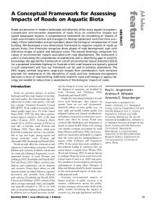
Figure 9. Digital photo of circular pattern of a bark distortion.
Proc. of SPIE Vol. 5011 47
4. CONCLUSIONS AND FUTURE WORK This paper has described an approach to detecting surface defects in logs. Robust estimation and filtering techniques are well suited to this application. The current programs can process an entire log-data sample that may contain large amounts of missing data and severe abnormal data (outliers) due to the nature of data collection. The methods and procedures in these programs apply robust estimation and filtering methodology and common heuristics to remove outliers and other undesirable data. Using such techniques results in residual data with a small standard deviation, yielding a sharper and cleaner representation of the entire log. The quality of the gray-level image lays a solid foundation for the remaining defect-detection process. It is suspected that ellipse fitting would provide better results in certain situations as it can better fit logs whose cross-sections are predominately elliptical in nature. However, while there are explicit iterative equations for circle fitting that estimate the center point and the radius, ellipse fitting is not as easy since there are more parameters involved: the center, two radii, and the orientation angle theta of the ellipse. At the cost of greater complexity and computation, fitting a conic or cylinder shape to the entire set of log data at once would provide a uniform surface of reference for generating the residual data. Any of these may improve the quality of data for use with texture processing and are being investigated further. The generation and initial processing of the residual image is not the final step of this research. Cleary, additional research is needed. At this point, only log unrolling and height analyses methods have been examined. To reach the final goal of locating and classifying surface defects, we are exploring the potential benefits of current image processing, computer vision, and pattern recognition techniques using residual data. The gradient information of a grayscale residual image, including gradient magnitude and gradient direction also is being analyzed. As stated earlier, Canny edge detection is detecting defects such as large sound knots. Methods that combine residual information with gradient (edge) could potentially detect more defects than using each kind of information alone. For example, a large sound knot has a special edge pattern and region feature (Fig. 8). In addition, binary and/or grayscale morphological operations17 can be tested their ability to aid in defect extraction. 5. DISCLAIMER The use of trade, firm, or corporation names is for the information of the reader. Such use does not constitute an official endorsement or approval by the U.S. Department of Agriculture, Forest Service, or the Virginia Polytechnic Institute and State University of any product or services to the exclusion of others that may be suitable. 6. REFERENCES 1. M. Samson. 1993. Method for assessing the effect of knots in the conversion of logs into structural lumber. Wood and Fiber Sci. 25(3):298-304. 2. X. Tian X, G.E. Murphy. 1997. Detection of trimmed and occluded branches of harvested tree stems using texture analysis. Int. J. of For. Eng. Vol. 8, No.2. 3. C.L. Todoroki. 2001. Volume and value variation with opening face positions: an investigation with pruned softwood logs. For. Prod. J. 51(1):36-46. 4. EG. Wagner, EW. Taylor, D.S. Ladd, C.W. McMillin, EL. Roder. 1989. Ultrafast CT scanning of an oak log for internal defects. For. Prod. J. 39(11/12): 62-64. 5. D. Zhu, R. Conners, E Lamb, P. Araman. 1991. A computer vision system for locating and identifying internal log defects using CT imagery. Proc. of the 4th Int. Conf. on Scanning Tech. in the Wood Ind., Miller Freeman Publishing, Inc., San Francisco, CA: pp: 1-13 6. D.L. Schmoldt. 1996. CT imaging, data reduction, and visualization of hardwood logs. In D. Meyer (Ed.) Proc. of the 1996 Hardwood Res. Symp. National Hardwood Lumber Association, Memphis, TN.
48 Proc. of SPIE Vol. 5011
7. S. Guddanti, S.l Chang. 1998. Replicating sawmill sawing with TOPSAW using CT images of a full length hardwood log. For. Prod. J. 48(1):72-75. 8. P. Li, A.L. Abbott, D.L. Schmoldt. 1996. Automated analysis of CT images for the inspection of hardwood logs. Proc. of the Int. Conf. on Neural Networks. Washington, D. c., USA. Volume 3, p.p.1744-1749. 9. S.M. Bhandarkar, T.D. Faust, M. Tang, 1999. CATALOG: a system for detection and rendering of internal log defects using computer tomography. Machine Vision and Applications. Springer-Verlag. 11: 171-190. 10. W. Gander, G.H Golub, R Strebel. 1994. Fitting of circles and ellipses-least squares solution. Tech. Rep. 217, Insitiut fur Eisenschaftliches Rechnen, ETH Zurich. Available via anonymous ftp from ftp://ftp.inf.ethz.chldoc/tech-reports/2xx/. 11. F.R Hampel, E.M. Ronchetti, P.J. Rousseeuw and W.A. Stahel. 1986. Robust Statistics: The approach based on
influence functions. John Wiley.
12. L. Mili, M.G. Cheniae, N.S. Vichare, P.J. Rousseeuw. 1996. Robust state estimation based on projection statistics. IEEE Trans. on Power Systems. Vol. 11. No.2. 13. P.J. Rousseeuw, B.C. Van Zomeren. 1991. Robust distances: simulations and cutoff values. W. Stahel and S. Weisberg, Directions in robust statistics and diagnostics, Part II, Springer-Verlag, 195-203. 14. RM. Haralick, L. Shapiro. 1992. Computer and robot vision. Vol. 2. Addison-Wesley. 15. J. Canny. 1986. A computational approach to edge detection. IEEE Trans. on Pattern Analysis and Mach. Intell. Vol. 8, No.6. 16. X. Tian, G.E. Murphy. 1997. Automated feature extraction and defect recognition from digital images of tree stems using texture analysis. Proc. of 1st Joint Australia and New Zealand Bien. Conf. on Digital Image and Vision Comput. Tech. and Appl. Massey University, Auckland, New Zealand. pp: 315- 320. 17. RM. Haralick, S.R Sternberg, X. Zhuang. 1987. Image analysis using mathematical morphology. IEEE Trans. on Pattern Anal. and Mach. Intell. Volume PAMI-9. No.4.
Proc. of SPIE Vol. 5011 49