1
On-Road Vehicle Detection Using Optical Sensors: A Review Zehang Sun1 , George Bebis2 and Ronald Miller3 1 eTreppid Technologies, LLC, Reno, NV 2 Computer Vision Laboratory, University of Nevada, Reno, NV 3 Vehicle Design R & A Department, Ford Motor Company, Dearborn, MI (zehang,bebis)@cs.unr.edu,
[email protected] Abstract—As one of the most promising applications of computer vision, vision-based vehicle detection for driver assistance has received considerable attention over the last 15 years. There are at least three reasons for the blooming research in this field: first, the startling losses both in human lives and finance caused by vehicle accidents; second, the availability of feasible technologies accumulated within the last 30 years of computer vision research; and third, the exponential growth of processor speed has paved the way for running computation-intensive video-processing algorithms even on a low-end PC in realtime. This paper provides a critical survey of recent vision-based on-road vehicle detection systems appeared in the literature (i.e., the cameras are mounted on the vehicle rather than being static such as in traffic/driveway monitoring systems).
I. I NTRODUCTION Every minute, on average, at least one person dies in a vehicle crash. Auto accidents also injure at least 10 million people each year, and two or three million of them seriously. The hospital bill, damaged property, and other costs are expected to add up to 1%-3% of the world’s gross domestic product [1]. With the aim of reducing injury and accident severity, pre-crash sensing is becoming an area of active research among automotive manufacturers, suppliers and universities. Vehicle accident statistics disclose that the main threats a driver is facing are from other vehicles. Consequently, developing on-board automotive driver assistance systems aiming to alert a driver about driving environments, and possible collision with other vehicles has attracted a lot of attention. In these systems, robust and reliable vehicle detection is the first step — a successful vehicle detection algorithm will pave the way for vehicle recognition, vehicle tracking, and collision avoidance. This paper provides a survey of on-road vehicle detection systems using optical sensors. More general overviews on intelligent driver assistance systems can be found in [2]. II. V ISION - BASED I NTELLIGENT V EHICLE R ESEARCH W ORLDWIDE With the ultimate goal of building autonomous vehicles, many government institutions have lunched various projects worldwide, involving a large number of research units working cooperatively. These efforts have produced several prototypes and solutions, based on rather different approaches [2]. In Europe, the PROMETHEUS program (Program for European Traffic with Highest Efficiency and Unprecedented Safety) pioneered this exploration. More than 13 vehicle manufactures and several research institutes from 19 European countries were involved. Several prototype vehicles and systems (i.e., VaMoRs, VITA, VaMP, MOB-LAB, GOLD) were designed as a result of
this project. Although the first research efforts on developing intelligent vehicles were seen in Japan in the 70’s, significant research activities were triggered in Europe in the late 80s and early 90s. MITI, Nissan and Fujitsu pioneered the research in this area by joining forces in the project “Personal Vehicle System” [3]. In 1996, the Advanced Cruise-Assist Highway System Research Association (AHSRA) was established among automobile industries and a large number of research centers [2]. In the US, a great deal of initiatives have been launched to address this problem. In 1995, the US government established the National Automated Highway System Consortium (NAHSC) [4], and launched the Intelligent Vehicle Initiative (IVI) in 1997. Several promising prototype vehicles/systems have been investigated and demonstrated within the last 15 years [5]. In March 2004, the whole world was stimulated by the “grand challenge” organized by DARPA [6]. In this competition, 15 fully-autonomous vehicles attempted to independently navigate a 250-mile (400 km) desert course within a fixed time period, all with no human intervention whatsoever - no driver, no remote-control, just pure computer-processing and navigation horsepower, competing for a $1 million cash prize. Although, even the best vehicle (i.e., “Red Team” from Carnegie Mellon) made only 7 miles, it is a very big step towards building autonomous vehicles in the future. III. ACTIVE VS . PASSIVE SENSORS The most common approach to vehicle detection is using active sensors such as lasers, lidar, or millimeter-wave radars. They are called active because they detect the distance of an object by measuring the travel time of a signal emitted by the sensors and reflected by the object. Their main advantage is that they can measure certain quantities (e.g., distance) directly requiring limited computing resources. Prototype vehicles employing active sensors have shown promising results. However, active sensors have several drawbacks, such as low spatial resolution, and slow scanning speed. Moreover, when a large number of vehicles are moving simultaneously in the same direction, interference among sensors of the same type poses a big problem. Optical sensors, such as normal cameras, are usually referred to as passive sensors because they acquire data in a non-intrusive way. One advantage of passive sensors over active sensors is cost. With the introduction of inexpensive cameras, we can have both forward and rearward facing cameras on a vehicle, en-
abling a nearly 360o field of view. Optical sensors can be used to track more effectively cars entering a curve or moving from one side of the road to another. Also, visual information can be very important in a number of related applications, such as lane detection, traffic sign recognition, or object identification (e.g., pedestrians, obstacles), without requiring any modifications to road infrastructures. On the other hand, vehicle detection based on optical sensors is very challenging due to huge within class variabilities. For example, vehicles may vary in shape, size, and color. Vehicle appearance depends on its pose and is affected by nearby objects. Illumination changes, complex outdoor environments (e.g. illumination conditions), unpredictable interactions between traffic participants, and cluttered background are difficult to control. To address some of the above issues, more powerful optical sensors are currently being investigated such as cameras operating under low light (e.g., Ford proprietary low light camera [7]) or cameras operating in the non-visible spectrum (e.g., Infrared (IR) camera [8]). Building cameras with internal processing power (i.e., vision chip) has also attracted great attention. In conventional vision systems, data processing takes place at a host computer. Vision chips have many advantages over conventional vision systems, for instance high speed, small size, lower power consumption, etc. The main idea is integrating photodetectors with processors on a very large scale integration [9].
approaches using information about symmetry, color, shadow, corners, horizontal/vertical edges, texture, and vehicle lights. A.1 Symmetry Vehicle images observed from rear or frontal view are in general symmetrical in horizontal and vertical directions. This observation was used as a cue for vehicle detection in the early 90s [10]. An important issue that arises when computing symmetry from intensity, however, is the presence of homogeneous areas. In these areas, symmetry estimation is sensitive to noise. In [11], information about edges was included in the symmetry estimation to filter out homogeneous areas. When searching for local symmetry, two issues must be considered carefully. First, we need a rough indication of where a vehicle is probably present. Second, even when using both intensity and edge maps, symmetry as a cue is still prone to false detections, such as symmetrical background objects, or partly occluded vehicles. A.2 Color Although few existing systems use color information to its full extent for HG, it is a very useful cue for obstacle detection, lane/road following, etc. Several prototype systems investigated the use of color information as a cue to follow lanes/roads, or segment vehicles from background [12]. Similar methods could be used for HG, because non-road regions within a road area are potentially vehicles or obstacles. The lack of deploying color information in HG is largely due to the difficulties of color-based object detection or recognition methods in outdoor settings. The color of an object depends on illumination, reflectance properties of the object, viewing geometry, and sensor parameters. Consequently, the apparent color of an object can be quite different during different times of the day, under different weather conditions, and under different poses.
IV. T HE TWO STEPS OF VEHICLE DETECTION In driver assistance applications, vehicle detection algorithms need to process the acquired images at real-time or close to realtime. Searching the whole image to locate potential vehicle locations is not realistic. The majority of methods reported in the literature follow two basic steps: (1) Hypothesis Generation (HG) where the locations of potential vehicles in an image are hypothesized, and (2) Hypothesis Verification (HV) where tests are performed to verify the presence of a vehicle in an image (see Fig. 1).
A.3 Shadow Using shadow information as a sign pattern for vehicle detection was initially discussed in [13]. By investigating image intensity, it was found that the area underneath a vehicle is distinctly darker than any other areas on an asphalt paved road. A first attempt to deploy this observation can be found in [14], though there was no systematic way to choose appropriate threshold values. The intensity of the shadow depends on the illumination of the image, which in turn depends on weather conditions. Therefore the thresholds are not, by no means, fixed. In [15], a normal distribution was assumed for the intensity of the free driving space. The mean and variance of the distribution were estimated using Maximum Likelihood (ML). It should be noted that the assumption about the distribution of road pixels might not always hold when true. For example, rainy weather conditions or bad illumination conditions will make the color of road pixels dark, causing this method to fail.
Fig. 1. Illustration of the two-step vehicle detection strategy
V. H YPOTHESIS G ENERATION The objective of the HG step is to find candidate vehicle locations in an image quickly for further exploration. HG approaches can be classified into one of the following three categories: (1) knowledge-based, (2) stereo vision based, and (3) motion-based.
A.4 Corners Exploiting the fact that vehicles in general have a rectangular shape, Bertozzi et al. proposed a corner-based method to hypothesize vehicle locations [16]. Four templates, each of them corresponding to one of the four corners, were used to detect all the corners in an image, followed by a search method to find the
A. Knowledge-based methods Knowledge-based methods employ a-priori knowledge to hypothesize vehicle locations in an image. We review below some 2
matching corners. For example, a valid upper-left corner should have a matched lower-right corner.
trices. The co-occurrence matrix contains estimates of the probabilities of co-occurrences of pixel pairs under predefined geometrical and intensity constraints. Using texture for HG can introduce many false detections. For example, when we drive a car outdoor, especially in some downtown streets, the background is very likely to contain textures.
A.5 Vertical/horizontal edges Different views of a vehicle, especially rear views, contain many horizontal and vertical structures, such as rear-window, bumper etc. Using constellations of vertical and horizontal edges has shown to be a strong cue for hypothesizing vehicle presence. Matthews et al. [17] applied horizontal edge detector on the image first, then the response in each column was summed to construct the profiles, and smoothed using a triangular filter. By finding the local maximum and minimum peaks, they claimed that they could find the horizontal position of a vehicle on the road. A shadow method, similar to that in [15], was used to find the bottom of the vehicle. Goerick et al. [18] proposed a method called Local Orientation Coding (LOC) to extract edge information. Handmann et al. [19] also used LOC, together with shadow information, for vehicle detection. Parodi et al. [20] proposed to extract the general structure of a traffic scene by first segmenting an image into four regions: the pavement, the sky, and two lateral regions using edge grouping. Groups of horizontal edges on the detected pavement were then considered for hypothesizing the presence of vehicles. Betke et al. [21] utilized edge information to detect distant cars. They proposed a coarse-to-fine search method looking for rectangular objects through analyzing vertical and horizontal profiles. In [22], vertical and horizontal edges were extracted separately using the Sobel operator. Then, a set of edge-based constraint filters were applied on those edges to segment vehicles from background. The edge-based constraint filters were derived from a prior knowledge about vehicles. Assuming that lanes have been successfully detected, Bucher et al. [23] hypothesized vehicle presence by scanning each lane starting from the bottom, trying to find the lowest strong horizontal edge. Utilizing horizontal and vertical edges as cues can be very effective. However, an important issue to be addressed, especially in the case of on-line vehicle detection, is how the choice of various parameters affects system robustness. These parameters include the threshold values for the edge detectors, the threshold values for picking the most important vertical and horizontal edges, and the threshold values for choosing the best maxima (i.e., peaks) in the profile images. Although a set of parameter values might work perfectly well under some conditions, they might fail in other environments. The problem is even more severe for an on-road vehicle detection system since the dynamic range of the acquired images is much bigger than that of an indoor vision system. A multi-scale driven method was investigated in [7] to address this problem. Although it did not root out the parameter setting problem, it did alleviate it to some extend.
A.7 Vehicle lights Most of the cues discussed above are not helpful for night time vehicle detection — it would be difficult or impossible to detect shadows, horizontal/vertical edges, or corners in images obtained at night conditions. Vehicle lights represent a salient visual feature at night. Cucchiara et al. [25] used morphological analysis for detecting vehicle light pairs in a narrow inspection area. B. Stereo-vision based methods There are two types of methods using stereo information for vehicle detection. One uses disparity map, while the other uses an anti-perspective transformation (i.e., Inverse Perspective Mapping (IPM)). B.1 Disparity map The difference in the left and right images between corresponding pixels is called disparity. The disparities of all the image points form the so-called disparity-map. If the parameters of the stereo rig are known, the disparity map can be converted into a 3-D map of the viewed scene. Computing the disparity map, however, is very time consuming. Hancock [26] proposed a method employing the power of the disparity while avoiding some heavy computations. In [27], Franke et al. argued that, to solve the correspondence problem, area-based approaches were too computationally expensive, and disparity maps from featurebased methods were not dense enough. A local feature extractor “structure classification” was proposed to solve the correspondence problem easier. B.2 Inverse perspective mapping The term “Inverse Perspective Mapping” does not correspond to an actual inversion of perspective mapping [28], which is mathematically impossible. Rather, it denotes an inversion under the additional constraint that inversely mapped points should lie on the horizontal plane. Assuming a flat road, Zhao et al. [29] used stereo vision to predict the image seen by the right camera, given the left image, using IPM. Specifically, they used the IPM to transform every point in the left image to world coordinates, and re-projected them back onto the right image, which were then compared against the actual right image. In this way, they were able to find contours of objects above the ground plane. Instead of warping the right image onto the left image, Bertozzi et al. [30] computed the inverse perspective map of both the right and left images. Although only two cameras are required to find the range and elevated pixels in an image, there are several advantages to use more than two cameras [31]. Williamson et al. investigated a triocular system [32]. Due to the additional computational costs, binocular system is more preferred in the driver assistance system.
A.6 Texture The presence of vehicles in an image cause local intensity changes. Due to general similarities among all vehicles, the intensity changes follow a certain pattern, referred to as texture in [24]. This texture information can be used as a cue to narrow down the search area for vehicle detection. Entropy was first used as a measure for texture detection. Another texture-based segmentation method suggested in [24] used co-occurrence ma3
“loose”, while others very strict. Parodi et al. [20] proposed a hypothesis verification scheme based on license plate and rear windows detection using constraints based on vehicle geometry. Handmann et al. [19] proposed a template based on the observation that the rear/frontal view of a vehicle has a “U” shape. During verification, they considered a vehicle to be present in the image if they could find the “U” shape (i.e., one horizontal edge, two vertical edges, and two corners connecting the horizontal and vertical edges). Ito et al. [40] used a very loose template to recognize vehicles. They hypothesized vehicle location using active sensors and verified those locations by checking whether pronounced vertical/horizontal edges and symmetry existed. Regensburger et al. [41] utilized a template similar to [40]. They argued that the visual appearance of an object depends on its distance from the camera. Consequently, they used two slightly different generic object (vehicle) models, one for nearby objects and the other for distant objects. A rather loose template was also used in [42], where the hypothesis was generated on the basis of road position and perspective constraints. The template contained a priori knowledge about vehicles: “a vehicle is generally symmetric, characterized by a rectangular bounding box which satisfies specific aspect ratio constraints”.
In general, stereo-vision based methods are accurate and robust only if the stereo parameters have been estimated accurately, which is really hard to guarantee in the on-road scenario. Since the stereo rig is on a moving vehicle, vibrations from car motion can shift the cameras while the height of the cameras can keep changing due to the suspension. Suwa et al. [33] proposed a method to adjust the stereo parameters to compensate for the error caused by camera shifting. Broggi et al. [34] analyzed the parameter drifts and argued that vibrations affect mostly the extrinsic camera parameters and not the intrinsic ones. A fast self-calibration method was investigated in that study. C. Motion-based methods All the cues discussed so far use spatial features to distinguish between vehicles and background. Another important cue that can be used is the relative motion obtained via the calculation of optical flow. Optical flow information can provide strong information for HG. Approaching vehicles at an opposite direction produce a diverging flow, which can be quantitatively distinguished from the flow caused by the car ego-motion [35]. On the other hand, departing or overtaking vehicles produce a converging flow. Giachetti et al. [35] developed first-order and second-order differential methods and applied them to a typical image sequence taken from a moving vehicle along a flat and straight road. The results were discouraging. Three factors causing poor performance were summarized in [35]: (a) displacement between consecutive frames, (b) lack of textures, and (c) shocks and vibrations. Given the difficulties faced by moving camera scenario, getting a reliable dense optical flow is not an easy task. Giachetti et al. [35] managed to re-map the corresponding points between two consecutive frames, by minimizing a distance measure. Kruger et al. [36] estimated the optical flow from spatio-temporal derivatives of the grey value image using a local approach. They further clustered the estimated optical flow to eliminate outliers. In contrast to dense optical flow, “sparse optical flow” utilizes image features, such as corners [37], local minima and maxima [38], or “Color Blob” [39]. Although it can only produce a sparse flow, feature based method can provide sufficient information for HG. In contrast to pixelbased optical flow estimation methods where pixels are processed independently, feature based methods utilize high level information. Consequently, they are less sensitive to noise. In general, motion-based methods can detect objects based on relative motion information. Obviously, this is a major limitation, for example, this method can not be used to detect static obstacles, which can represent a big threat.
B. Appearance-based methods Appearance-based methods learn the characteristics of the vehicle class from a set of training images which capture the variability in vehicle appearance. Usually, the variability of the nonvehicle class is also modelled to improve performance. First, each training image is represented by a set of local or global features. Then, the decision boundary between the vehicle and non-vehicle classes is learned either by training a classifier (e.g., Neural Network (NN)) or by modelling the probability distribution of the features in each class (e.g., using the Bayes rule assuming Gaussian distributions). In [17], Principal Component Analysis (PCA) was used for feature extraction and Neural Networks (NNs) for classification. All the vehicle candidates were scaled to 20x20, then this 20x20 scaled image was divided into 25 4x4 small windows. PCA was applied on every sub window and the output of the “local PCA” was provided to a NN to verify the hypothesis. Different from [17], Wu et al. [43] used standard PCA for feature extraction method for vehicle detection, together with a nearest-neighbor classifier. Goerick et al. [18] used a method called Local Orientation Coding (LOC) to extract edge information. The histogram of LOC within the area of interest was then provided to a NN for classification. Kalinke et al. [24] designed two models for vehicle detection: one for sedans, and the other for trucks. Hausdorrf distances between the hypothesized vehicles and the models in terms of LOC were the input to a NN. The outputs were sedans, trucks or background. Similar to [18], Handmann et al. [19] utilized the histogram of LOC, together with a NN, for vehicle detection. Moreover, the Hausdorrf distance was used for the classification of trucks and cars such as in [24]. A statistical model for vehicle detection was investigated by Schneiderman et al. [44]. A view-based approach using multiple detectors was employed to cope with viewpoint variations. The statistics of both object and “non-object” appearance were represented using the product of two histograms with each histogram represent-
VI. H YPOTHESIS V ERIFICATION The input to the HV step is the set of hypothesized locations from the HG step. During HV, tests are performed to verify the correctness of a hypothesis. HV approaches can be classified into two main categories: (1) template-based methods and (2) appearance-based methods. A. Template-based methods Template-based methods use predefined patterns of the vehicle class and perform correlation between the image and the template. Some of the templates in the literature are very 4
handle different cases. We discuss below several research directions for moving this area forward.
ing the joint statistics of a subset Haar wavelet features in [44] and their position on the object. A different statistical model was investigated by Weber et al. [45]. They represented each vehicle image as a constellation of local features and used the Expectation-Maximization (EM) algorithm to learn the parameters of the probability distribution of the constellations. An overcompleted dictionary of Haar wavelet features was utilized in [46] for vehicle detection. They argued that the over-completed representation provided a richer model and spatial resolution and was more suitable for capturing complex patterns. Sun et al. [47][7] went one step further by arguing that the actual values of the wavelet coefficients are not very important for vehicle detection. In fact, coefficient magnitudes indicate local oriented intensity differences, information that could be very different even for the same vehicle under different lighting conditions. Following this observation, they proposed using quantized coefficients to improve detection performance. Feature extraction using Gabor filters was investigated in [48]. Gabor filters provide a mechanism for obtaining orientation and scale tunable edge and line detectors. Vehicles contain strong edges and lines at different orientation and scales, thus, this type of features are very effective for vehicle detection.
A. Vehicle classification The majority of reported works aim only at detecting/tracking vehicles without differentiating among vehicle types. Given many different participants on the road (sedan, trail truck, motorbikes, etc.), knowing exactly what kind of participants are around the host vehicle will benefit driver assistance systems. B. Feature selection Building accurate and robust vehicle detection algorithms, especially in the framework of supervised learning, requires employing a good set of features. In most cases, a large number of features are extracted to compensate for the fact that relevant features are unknown a − priori. It would be ideal if we could use only those features which have great separability power while ignoring or paying less attention to the rest. For example, to allow a vehicle detector to generalize nicely, it would be nice to exclude features encoding fine details which might be present in particular vehicles only. Finding out what features to use for classification/recognition is referred to as feature selection. Sun et al. [49][50] have investigated various feature selection schemes in the context of vehicle detection, showing significant performance improvements. However, selecting an optimum feature subset (i.e., leading to high generalization performance) is still an open problem.
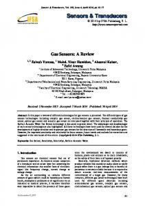
VII. C HALLENGES A HEAD Although many efforts have been put into the vehicle detection research area, many algorithms/systems have already been reported, many prototype vehicles have already been demonstrated, a highly robust and reliable system is yet to be built. In general, surrounding vehicles can be classified into three categories according to their relative positions to the host vehicle: (a) overtaking vehicles, (b) mid-range/distant vehicles, and (c) close-by vehicles (see Fig. 2).
C. Sensor fusion Information from a single sensor is not enough for a driver assistance system to manage high level driving tasks in dense traffic environments. Substantial research efforts are required to develop systems employing information from multiple sensors, both active and passive, effectively. D. Failure detection An on-board vision sensor will face adverse operating conditions, and it may reach a point where it might not be able to provide good quality data to meet minimum system performance requirements. In these cases, the driver assistance system may not be able to fulfil its desired responsibilities correctly (e.g., issuing severe false alerts). A reliable driver assistance system should be able to evaluate its performance and disable its operation when it can not provide reliable traffic information any more.
Fig. 2. Detecting vehicles in different regions requires different methods. A1: Close by regions; A2: Overtaking regions; A3: Mid-range/distant regions.
In the close-by regions, we may only see part of the vehicle. In this case, there is no free space in the captured images, which makes the shadow/edge based methods inappropriate. In the overtaking regions, only the side view of the vehicle is visible while appearance changes fast. Methods detecting vehicles in these regions might be better to employ motion information or dramatic intensity changes [21]. Detecting vehicles in the mid-range/distant region is relatively easier since the full view of a vehicle is available and appearance is more stable. Real-time on-road vehicle detection is so challenging, that none of the HG methods discussed in Section V can solve it alone completely. Different cues/methods would be required to
E. Hardware implementation Vehicle detection systems should be able to process information very fast to allow enough time for the drivers to react in case of an emergency. Among many options, real-time performance based on hardware implementations stand out for their simplicity and efficiency. VIII. C ONCLUSIONS We presented a critical survey of vision-based on-road vehicle detection systems — one of the most important components of a driver assistance system. Judging from the research activities 5
underway worldwide, it is certain that this area will continue to be among the hottest research areas in the future. Major motor companies, government agencies, and universities, are all expected to work together to make significant progress in this area over the next few years.
[24] T. Kalinke, C. Tzomakas und W. v. Seelen, “A texture-based object detection and an adaptive model-based classification,” IEEE International Conference on Intelligent Vehicles, pp. 143–148, 1998. [25] R. Cucchiara and M. Piccardi, “Vehicle detection under day and night illumination,” International ICSC Symposium on Intelligent Industrial Automation, 1999. [26] J. Hancock, “High-speed obstacle detection for automated highway applications,” Tech. Rep. RI-TR-97-17, Carnegie Mellon University, 1997. [27] U. Franke and I. Kutzbach, “Fast stereo based object detection for stop&go traffic,” Intelligent Vehicle, pp. 339–344, 1996. [28] H. Mallot, H. Bulthoff, J. Little, and S. Bohrer, “Inverse perspective mapping simplifies optical flow computation and obstacle detection,” Biological Cybernetics, vol. 64, no. 3, pp. 177–185, 1991. [29] G. Zhao and S. Yuta, “Obstacle detection by vision system for autonomous vehicle,” Intelligent vehicles, pp. 31–36, 1993. [30] M. Bertozzi and A. Broggi, “Gold: A parallel real-time stereo vision system for generic obstacle and lane detection,” IEEE Trans. on Image Processing, vol. 7, pp. 62–81, 1998. [31] M. Okutomi and T. Kanade, “A multiple-baseline stereo,” IEEE Trans. Pattern Analysis and Machine Intelligence, vol. 15, pp. 353–363, 1993. [32] T. Williamson and C. Thorpe, “A trinocular stereo system for highway obstacle detection,” IEEE International Conference on Robotics and Automation, 1999. [33] M.Suwa, Y. Wu, M. Kobayashi et al., “A stereo-based vehicle detection method under windy conditions,” IEEE Intelligent vehicle symposium, pp. 246–249, 2000. [34] A. Broggi, M. Bertozzi and A. Fascioli, “Self-calibration of a stereo-vision system for automotive applications,” IEEE Intl. Conf. on Robotics and Automation, 2001. [35] A. Giachetti, M. Campani, and V. Torre, “The use of optical flow for road navigation,” IEEE transactions on robotics and automation, vol. 14, no.1, pp. 34–48, 1998. [36] W. Kruger, W. Enkelmann, and S. Rossle, “Real-time estimation and tracking of optical flow vectors for obstacle detection,” IEEE Intelligent vehicle symposium, pp. 304–309, 1995. [37] J. Weng, N. Ahuja, and T. Huang, “Matching two perspective views,” IEEE Trans. Pattern Analysis and Machine Intelligence, vol. 14, pp. 806– 825, 1992. [38] D. Koller, N. Heinze, and H. Nagel, “Algorithmic characterization of vehcile trajectories from image sequence by motion verbs,” IEEE International Conference on Computer Vision and Pattern Recognition, pp. 90– 95, 1991. [39] B. Heisele and W. Ritter, “Obstacle detection based on color blob flow,” IEEE Intelligent vehicle symposium, pp. 282–286, 1995. [40] T. Ito, K. Yamada and K. Nishioka, “Understanding driving situations using a network model,” Intelligent vehicles, pp. 48–53, 1995. [41] U. Regensburger and V. Graefe, “Visual recognition of obstacles on roads,” Intelligent Robots and Systems (V. Graefe, ed.), pp. 73–86, Academic Press, Inc., 1995. [42] A. Bensrhair, M. Bertozzi, A. Broggi, P. Miche, S. Mousset and G. Moulminet, “A cooperative approach to vision-based vehicle detection,” IEEE Intelligent Transportation Systems, pp. 209–214, 2001. [43] J. Wu and X. Zhang, “A pca classifier and its application in vehicle detection,” IEEE International Joint Conference on Neural Networks, 2001. [44] H. Schneiderman and T. Kanade, “A statistical method for 3d object detection applied to faces and cars,” IEEE International Conference on Computer Vision and Pattern Recognition, pp. 746–751, 2000. [45] M. Weber, M. Welling, and P. Perona, “Unsupervised learning of models for recognition,” European Conference on Comptuer vision, pp. 18–32, 2000. [46] C. Papageorgiou and T. Poggio, “A trainable system for object detection,” International Journal of Computer Vision, vol. 38, no 1, pp. 15–33, 2000. [47] Z. Sun, G. Bebis, and R. Miller, “Quantized wavelet features and support vector machines for on-road vehicle detection,” IEEE International Conference on Control, Automation, Robotics and Vision, December, 2002, Singapore. [48] Z. Sun, G. Bebis, and R. Miller, “On-road vehicle detection using gabor filters and support vector machines,” IEEE International Conference on Digital Signal Processing, July, 2002,Greece. [49] Z. Sun, G. Bebis, and R. Miller, “Boosting object detection using feature selection,” IEEE International Conference on Advanced Video and Signal Based Surveillance, 2003. [50] Z. Sun, G. Bebis, and R. Miller, “Evolutionary gabor filter optimization with application to vehicle detection,” IEEE International Conference on Data Mining, 2003.
Acknowledgements This work was supported by Ford Motor Company under grant No.2001332R, the University of Nevada, Reno under an Applied Research Initiative (ARI) grant, and in part by NSF under CRCD grant No.0088086. R EFERENCES [1] [2] [3] [4] [5] [6] [7] [8]
[9] [10] [11] [12] [13] [14] [15] [16] [17] [18] [19] [20] [21] [22] [23]
W. Jones, “Building safer cars,” IEEE Spectrum, vol. 39, no 1, pp. 82–85, 2002. M. Bertozzi, A. Broggi, M. Cellario, A. Fascioli, P. Lombardi, and M. Porta, “Artifical vision in road vehicles,” Proceedings of the IEEE, vol. 90, no. 7, pp. 1258–1271, 2002. S. Tsugawa and Sadayuki, “Vision-based vehcile on japan: Machine vision systems and driving control systems,” IEEE Trans. on Ind. El.???, vol. 41, no. 4, pp. 398–405, 1994. Vehicle-highway automation activities in the United States. U.S. Dept of Transportation, 1997. C. Thorpe, J.D. Carlson, D. Duggins, J. Gowdy, R. MacLachlan, C. Mertz, A. Suppe, and C. Wan, “Safe robot driving in cluttered environments,” 11th International Symposium of Robotics Research, 2003. M. Walton, “Robots fail to complete grand challenge,” CNN news, March 14, 2004. Z. Sun, R. Miller, G. Bebis, and D. DiMeo, “A real-time precrash vehicle detection system,” IEEE International Workshop on Application of Computer Vision, Dec., 2002. L. Andreone, P. Antonello, M. Bertozzi, A. Broggi, A. Fascioli, and D. Ranzato, “Vehicle detection and localization in infra-red images,” The IEEE 5th International Conference on Intelligent Transportation Systems, 2002. K. Yamada, “A compact integrated vision motion sensor for its applications,” IEEE Transactions on Intelligent Transportation System, vol. 4, no. 1, pp. 35–41, 2003. A. Kuehnle, “Symmetry-based recognition for vehicle rears,” Pattern Recognition Letters, vol. 12, pp. 249–258, 1991. M. Bertozzi, A. Broggi, A. Fascioli, and S. Nichele, “Stereo vision-based vehicle detection,” IEEE Intelligent vehicle symposium, pp. 39–44, 2000. D. Guo, T. Fraichard, M. Xie, and C. Laugier, “Color modeling by spherical influence field in sensing driving environment,” IEEE Intelligent Vehicle Symposium, pp. 249–254, 2000. H.Mori and N. Charkai, “Shadow and rhythm as sign patterns of obstacle detection,” International Symposium on industrial exlectronics, pp. 271– 277, 1993. E. Dickmanns, et. al., “The seeing passenger car ‘vamors-p’,” International Symposium on Intelligent Vehicles’94, pp. 24–26, 1994. C. Tzomakas and W. Seelen, “Vehicle detection in traffic scenes using shadows,” Tech. Rep. 98-06, Institut fur neuroinformatik, Ruht-universitat, Bochum, Germany, 1998. M. Bertozzi, A. Broggi, and S. Castelluccio, “A real-time oriented system for vehicle detection,” Journal Of Systems Architecture, pp. 317–325, 1997. N. Matthews, P. An, D. Charnley, and C. Harris, “Vehicle detection and recognition in greyscale imagery,” Control Engineering Practice, vol. 4, pp. 473–479, 1996. C. Goerick, N. Detlev and M. Werner, “Artificial neural networks in realtime car detection and tracking applications,” Pattern Recognition Letters, vol. 17, pp. 335–343, 1996. U. Handmann, T. Kalinke, C. Tzomakas, M. Werner, and W. Seelen, “An image processing system for dirver assistance,” vol. 18, no. 5, 2000. P. Parodi and G. Piccioli, “A feature-based recognition scheme for traffic scenes,” IEEE Intelligent Vehicles Symposium, pp. 229–234, 1995. M. Betke, E. Haritaglu and L. Davis, “Real-time multiple vehicle detection and tracking from a moving vehicle,” vol. 12, no. 2, 2000. N. Srinivasa, “A vision-based vehicle detection and tracking method for forward collision warning,” IEEE Intelligent vehicle symposium, pp. 626– 631, 2002. T. Bucher, C. Curio et al., “Image processing and behavior planning for intelligent vehicles,” IEEE Transactions on Industrial Electronics, vol. 50, no. 1, pp. 62–75, 2003.
6