Email: {vinay,tian,mdfeuer}@research.att.com. AbstractâAn ... combination of a multiple access and broadcast communication system. ... (λ2,F2). An end-to-end all-optical link between a sender .... composite bit stream for a single sender.
On the Capacity of a Hybrid Broadcast Multiple Access System for WDM Networks ∗ AT&T
Vinay A. Vaishampayan∗ , Chao Tian∗ , Mark D. Feuer† , Labs-Research, Shannon Laboratory, 180 Park Ave., Florham Park, NJ 07932 † AT&T Labs-Research, 200 Laurel Ave., Middletown, NJ 07748, Email: {vinay,tian,mdfeuer}@research.att.com
Abstract—An information theoretic analysis is presented for a layered communication system designed for enhancing the network management capabilities of a wavelength division multiplexed (WDM) optical network. A theoretical model for the layered communication system is developed, and is seen to be a combination of a multiple access and broadcast communication system. Inner and outer bounds for the capacity region are derived for both general discrete memoryless model and the Gaussian model, which provide a complete solution for the symmetric problem. Comparisons are drawn between the coding technique suggested by an information theoretic analysis and the coding method used in a working implementation.
I. I NTRODUCTION In an optical wavelength division multiplexed network with optical routing, data is converted into optical form at the source and remains in optical form throughout its passage to the destination. While optical routing has many advantages, the fact that data is in optical form rather than electronic form while in transit poses a problem for network service providers in terms of configuration management and verification. To illustrate the kind of problem that arises, consider an optical network with two transmitters A, B and two receivers C, D and a single routing node, N1 as illustrated in Fig. 1. Information from A is to be sent to destination C using (wavelength,fiber) pairs (λ1 , F1 ), (λ1 , F2 ) and to destination D using (λ2 , F1 ) and (λ2 , F4 ). Simultaneously, information from sender B is to be sent to receiver D, using (λ1 , F3 ), (λ1 , F4 ) and to receiver C using (λ2 , F3 ), (λ2 , F2 ). An end-to-end all-optical link between a sender and receiver is called a lightpath in the optical networking literature. In this example, the network has four lightpaths ((λ1 , F1 ), (λ1 , F2 )), ((λ2 , F1 ), (λ2 , F4 )), ((λ1 , F3 ), (λ1 , F4 )) and ((λ2 , F3 ), (λ2 , F2 )). Suppose, due to an error in a routing table entry at node N1 that wavelength λ1 on F1 is mistakenly routed to λ1 on F4 and λ1 on F3 is mistakenly routed to λ1 on F2 . Such an error could easily occur due to operator error or due to equipment malfunction. In a large network, with many nodes, even if the error is quickly detected at the destination, identification of the faulty router might be complicated, resulting is a serious network outage. One approach to detecting and rapidly correcting errors such as these is to make essential information related to each lightpath available electronically within the network. If properly designed, this would avoid the costs of full optical to electronic conversion, and would greatly enhance the ability
A
F1
λ1 λ2
λ1 λ2
F2
C
N1
λ1 λ2 B
F3
λ1 λ2 Optical Label Reader
F4
D
Fig. 1. An illustration of an optically routed network with four lightpaths and label readers.
of network administrators to gather information about the state of the network. A system to address this requirement has been proposed in [8], [3]. The basic idea is to embed a periodic label stream into each payload data stream, where a label serves as a unique identifier for each lightpath. Label readers, deployed at several points throughout the network, as illustrated in Fig. 1 would read these labels, and send label and fiber information back to a central system which would check for and identify routing errors of the kind described above. Other uses for this system have also been proposed, e.g., as a voice communication link for system operators. Since many label readers would need to be deployed at points within the network, it is important that the cost of a label reader be kept low. The approach to managing label reader cost in [8], [3] is to run it at a clock rate commensurate with the label data rate (which is typically 5-6 orders of magnitude smaller than the payload data rate), and by forgoing the use of wavelength filters. This immediately precludes multiplexing the label stream into the payload stream. In addition, the lack of a wavelength filter requires the adoption of some kind of multiple access coding strategy. Previous approaches to addressing this problem include analog over-modulation methods [1], [7]. A communication theoretic analysis of the problem was presented in [8]. An analysis of a new decoder designed to improve performance under a specific form of asynchronism was presented in [9]. Enhancements and new applications have been presented in [4] and [5]. This paper presents the first information theoretic analysis of the above system, drawing on the previous wellknown work on broadcast channel and multiple access channels [2]. The paper is organized as follows. Sec. II describes an implementation of the layered communication system. A theoretical model for the layered communication system is
A1
CDMA Signature Sequence xor
Zmn 1 From other Optical Transmitters
Xmn 1
M1
^ M1
Ymn 1 +
Encoder-1
Decoder-1 n
A1 M1
Optical Fiber
Constant Weight Code (N,K,W)
Slow Photodiode
Wavelength Demux
Fig. 2.
xor
Chip-level Averager
Fast Photodiode
Optical Transmitter
Wavelength Multiplexer
Constant Weight Decoder
M2
Xmn 2 Encoder-2
Fig. 3.
^ M1
Encoder and Decoder block diagrams.
developed in Sec. III. Inner and outer bounds for the capacity region are presented in Sec. IV for the general case, and in Sec. V, for the Gaussian case. Some concluding remarks are given in Sec. VI. II. S YSTEM D ESCRIPTION The method used in [8] is a combination of a directsequence code-division multiple access (DS-CDMA) scheme to address the multiple access nature of the problem created by the lack of a wavelength filter in the label reader, and a coding technique based on constant weight codes, for handling the broadcast nature of the problem and ensuring that the clock rates for the label reader are commensurate with the label stream data rate. For the purposes of this paper, we will consider the system illustrated in Fig. 2 which consists of an encoder, with access to two independent bit streams, a highrate payload or main data stream, M1 , and a low-rate auxiliary data stream, A1 , where the subscript identifies the lightpath. The encoder for lightpath 1 maps the data streams (M1 , A1 ) to a bit stream which modulates a light source for transmission over a fiber. The encoder operates as follows. A block of K bits from M1 is encoded into a codeword of a constant weight code of block length N and weight W , with W < N/2. Also, in the encoder, each bit of the auxiliary stream modulates a CDMA signature vector assigned to that lightpath. Each ‘on’ bit (chip) of the modulated signature vector is then replaced by the constant weight codeword selected by the main data stream, and each ‘off’ chip is replaced with the complement of the codeword of constant weight selected by the main data stream at that time instant. In effect the system replaces the the chip waveforms of a standard DS-CDMA system with a chip waveform chosen from a codebook of chip waveforms by the main data stream. The resulting binary stream is the desired composite bit stream for a single sender. In a large network with several lightpaths, each lightpath will be assigned a unique signature vector. There are two kinds of decoders—an auxiliary stream decoder, or label reader, which as mentioned before is deployed at several points within the network, and a main data stream decoder, which is deployed at the end of its lightpath. The main data stream decoder operates at a high clock rate and
Decoder-0
+ Y0 Decoder-2
Ymn 2
A2
^ A1 ^ A2 ^ Au
Multiuser Detector
Payload Rate Averager
Optical Fiber
^ ^ (A1,A2)
Z0 Zmn 2
^ M2
Channel model and communication system diagram.
first blocks the incoming stream into blocks of length N bits. If the block has weight greater than N/2 the entire block is complemented, and then decoded using a constant weight decoder to obtain the main stream bits. It is worth noting that knowledge of the auxiliary bit stream is not necessary for decoding the main data stream. The waveform presented to the auxiliary data stream decoder is a superposition of U data streams present on that fiber because, by design, the front-end of the auxiliary stream decoder does not have a wavelength filter. The auxiliary stream decoder thus consists of a multiuser detector, where knowledge of the signature vectors is used to decode and separate the auxiliary data streams. Note that the auxiliary stream decoder clock rate is 1/N times the clock rate of the payload decoder. We refer the reader to [8] for further details, but close by mentioning that the parameters of the constant weight code, N and W , allow the user to tradeoff the rate between the payload and auxiliary data streams. III. C HANNEL M ODEL AND P ROBLEM F ORMULATION Throughout this paper, a real vector of dimension m is denoted Y1m = (Y1,1 , Y1,2 , . . . , Y1,m ). Y1mn is shorthand for (Y1m )n = ((Y1,1 , Y1,2 , . . . , Y1,m ), (Y1,m+1 , . . . , Y1,m+n ), . . . n . . . , (Y1,m(n−1)+1 , . . . , Y1,mn )). Y1,i will denote n (Y1,i , Y1,i+m , . . . , Y1,i+m(n−1) ). Similarly Y1,i:j will denote the vector ((Y1,i , . . . , Y1,j ), (Y1,i+m , . . . , Y1,j+m ), . . . (Y1,i+(n−1)m , . . . , Y1,j+(n−1)m )). Vectors are to be regarded as column vectors. The channel model that we consider, as illustrated in Fig. 3, is an abstraction of the model used in the system described in Sec. II and is a memoryless multiple access, broadcast channel hybrid, with two inputs and three outputs; the system model and results presented in this work can be straightforwardly extended to the case of more users. We are thus considering the two-lightpath case for our analysis, and in particular we assume the channel inputs are real-valued, and the channel noises are Gaussian and additive. The two vector inputs X1m , X2m are of dimension m, two vector outputs Y1m and Y2m , are also of dimension m whereas output Y0 is a scalar quantity. The inputs and outputs are related as follows. Y1m = X1m + Z1m , Z1m is independent of X1m and Z1m ∼ N (0, N1 Im ). Im is the m × m identity matrix. Similarly Y2m = X2m + Z2m , Z2m is independent of X2m and Z2m ∼ N (0, N2 Im ). Y0 = hY1m + Y2m , φm i+Z0 , where φm is a given vector of dimension m and unit norm, Z0 ∼ N (0, N0 ) and is independent of Y1m , Y2m . The vector φm is the mth column of an orthogonal matrix Φ = (φ1 , φ2 , . . . , φm ). We define Neff = N0 + N1 + N2 .
Encoder-i wishes to send the message pair (mi , ai ), mi ∈ [1 : 2nRMi ], ai ∈ [1 : 2nRAi ], i = 1, 2. The messages are mutually independent and uniformly distributed over their supports. Encoder-i maps (mi , ai ) to codeword xmn i (mi , ai ) which lies in codebook Ci , i = 1, 2. The transmitted signal on each channel is subject to a power constraint, i.e. E(kXimn k2 )/n ≤ Pi , i = 1, 2. Decoder-0 observes Y0n and decodes the auxiliary messages ˆ ˆ i, (A1 , Aˆ2 ). Decoder-i observes Yimn and decodes message M ˆ i = 1, 2. Let EMi , i = 1, 2 be the event (Mi 6= Mi ) and let EAi be the event (Ai 6= Aˆi ), i = 1, 2. Rate quadruple (RM1 , RA1 , RM2 , RA2 ) is said to be achievable if there exists a sequence of codebooks C1 of size 2n(RA1 +RM1 ) and C2 of size 2n(RA2 +RM2 ) with nm symbols such that the S channel S S error probability P (EA1 EM1 EA2 EM2 ) can be made arbitrarily small as the block length of the code n → ∞. A more general model of the channel is given via the joint channel input and output distribution p(y0 |y1 , y2 )p(y1 |x1 )p(y2 |x2 )p(x1 )p(x2 ), (1) where the channel inputs and outputs are of a more general nature than the vector model described above. However, the degraded structure is preserved, i.e., the multiple access receiver signal is a degraded version of the signals at the main receivers. We shall start by treating this general model in the discrete memoryless setting in the next section. The capacity region we are interested in is the closure of the collections of all such achievable rate quadruples, which is denoted as C. The symmetric rate point is of particular interest, where RA1 = RA2 and RM1 = RM2 , when the channel is also symmetric in the sense that if we switch the role of (x1 , y1 ) and (x1 , y2 ) in (1), the joint distribution remains the same. For this case, the main stream channel capacity subject to an auxiliary stream constraint is written as C(RA ) , max RM , where the maximization is taken over the pairs of (RA , RM ) such that (RM , RA , RM , RA ) ∈ C. IV. C HARACTERIZATIONS FOR G ENERAL C HANNELS In this section we focus on the discrete memoryless channel model given in (1), and provide inner and outer bounds for C and a complete characterization of C(RA ). A. Main Results Let Q, U1 , U2 be auxiliary random variables jointly distributed with X1 , X2 , Y0 , Y1 , Y2 as p(y0 |y1 , y2 )p(y1 |x1 )p(y2 |x2 ) · p(x1 |u1 )p(x2 |u2 )p(u1 |q)p(u2 |q)p(q). (2) Let C∗ be the closure of rate quadruples (RM1 , RA1 , RM2 , RA2 ) that satisfy the conditions RA1 ≤ I(U1 ; Y0 |U2 , Q), RA2 ≤ I(U2 ; Y0 |U1 , Q), RA1 + RA2 ≤ I(U1 , U2 ; Y0 |Q), RM1 ≤ I(X1 ; Y1 |U1 , Q), RM2 ≤ I(X2 ; Y2 |U2 , Q) (3) for some random variables Q, U1 , U2 , X1 , X2 as given in (2). Then Theorem 1 establishes that C∗ is an inner bound of C.
Theorem 1: C∗ ⊆ C for any discrete memoryless channel specified by (1). Similarly to the multiple access case, the random variable Q is a simple time-sharing random variable, whose cardinality can be chosen to be less than 6; moreover by using conventional technique, the cardinality of Ui can be bounded by |Xi | + 3 for i = 1, 2 where |Xi | is the cardinality of input Xi . We are not able to prove a matching converse for C. However, the following theorem establishes an outer bound. Theorem 2: For any (RM1 , RA1 , RM2 , RA2 ) ∈ C, RA1 + RA2 < I(U1 , U2 ; Y0 |Q) RM1 + RM2 < I(X1 ; Y1 |U1 , Q) + I(X2 ; Y2 |U2 , Q), (4) for some random variables Q, U1 , U2 , X1 , X2 as given in (2). The cardinality of Q in Theorem 2 can be limited to 3, and Ui can be bounded by |Xi | + 1 for i = 1, 2. Theorem 1 and Theorem 2 provide a complete characterization of C(RA ) for the symmetric case, as given in the following theorem. Theorem 3: 1 1 C(RA ) = max [I(X1 ; Y1 |U1 , Q) + I(X2 ; Y2 |U2 , Q)], 2 2 (5) where the maximization is in the set of random variables Q, U1 , U2 , X1 , X2 satisfying (2), under the constraint that 1 RA ≤ I(U1 , U2 ; Y0 |Q). (6) 2 Note that C(RA ) is only defined for symmetric channels in this work. Theorem 3 does not apply for the asymmetric case. B. Proof of Theorem 1 We only give an outline of the coding scheme, as it is essentially a combination of the coding scheme for the multiple access channel and the degraded broadcast channel. For codebook 1, pick 2nRA1 vectors {un1 (i), i = 1, 2, . . . , 2nRA1 } independently, with each component chosen independently and identically (iid) according to p(u1 ). For each code vector un1 (i) pick 2nRM1 conditional codevectors {xn1 (i, j), j = 1, 2, . . . , 2nRM1 } independently, where the jth component m-vector of xn1 (i, j) is chosen independently with conditional distribution p(x1 |u1,j (i)). Thus C1 = {xn1 (i, j), j = 1, 2, . . . , 2nRM1 }. A similar procedure with auxiliary random variable U2 , jointly distributed according to p(y2 , x2 , u2 ) = p(y2 |x2 )p(x2 |u2 )p(u2 ) is used to construct codebook C2 . Given channel output y0n , Decoder-0 searches for a unique pair (ˆ a1 , a ˆ2 ), such that (y0n , un1 (ˆ a1 ), un2 (ˆ a2 )) is n in A� , the set of jointly �-typical sequences with respect to the joint distribution p(y0 , u1 , u2 ). If such a pair is not unique or if no such pair is found, an error is declared. The decoder for M1 , Decoder-1, observes y1n and first looks for the unique message a ˆ1 such that (y1n , u1 (ˆ a)) is in An� , if successful, then looks for a unique m ˆ 1 such that (y1n , xn1 (m ˆ 1, a ˆ1 ), u1 (ˆ a)) is in An� and declares mˆ1 to be the decoded message; if the pair is not unique or none is found, an error is declared. A similar procedure is used by the decoder for m ˆ 2. The error probability analysis can largely follow the those given in [2] for broadcast channel and multiple access channel. However, here the superposition code is not used exactly on
a degraded broadcast channel, and it is not immediately clear that Decoder-1 can successfully decode the message a1 with high probability. It is however easy to show that the probability of this error event can be made arbitrarily small as long as RA1 < I(U1 ; Y1 ). Notice that the rate RA1 in this coding scheme should also satisfy RA1 < I(U1 ; Y0 |U2 ) due to the decoding requirement at Decoder-0. The following inequality shows that the former bound is in fact redundant. (a)
I(U1 ; Y0 |U2 ) = I(U1 ; Y0 , U2 ) ≤ H(U1 ) − H(U1 |Y0 , U2 , Y1 ) (b)
= H(U1 ) − H(U1 |Y1 ) = I(U1 ; Y1 ). (7) where (a) is because conditioning reduces entropy, and (b) is because of the Markov chain (Y0 , U2 ) ↔ Y1 ↔ U1 . Putting various bounds together eventually leads to the conditions (3) in Theorem 1. C. Proof of Theorem 2 The outer bound is essentially derived by letting Decoder-1 and Decoder-2 cooperate, where Decoder-0 sees a degraded form of the inputs to Decoder-1 and Decoder-2, and thus the proof closely follows the degraded broadcast channel proof [2]. The subtlety is that the encoders are separate, and thus the joint distribution of the auxiliary random variable U1 and U2 have to tracked carefully in the proof to avoid any violation. Proof: Following the converse proof given in [2], define U1,i , (A1 , Y1i−1 ) and U2,i , (A2 , Y2i−1 ), it is not difficult to write the following inequality n X n(RA1 + RA1 ) ≤ I(Y0,i ; U1,i , U2,i ) + n�n . (8) i=1
It is also straightforward to show n X n(RM1 + RM2 ≤ I(X1,i , X2,i ; Y1,i , Y2,i |U1,i , U2,i ) + n�n i=1
=
n X
I(X1,i ; Y1,i |U1,i ) + I(X2,i ; Y2,i |U2,i ) + n�n ,
(9)
i=1
where the last step is because (X1,i , Y1,i , U1,i ) is independent of (X2,i , Y2,i , U2,i ). The proof can now be completed by observing that U1,i ↔ X1,i ↔ Y1,i is indeed a Markov chain, and similarly for U2,i ↔ X2,i ↔ Y2,i , and then introducing the time-sharing random variable Q. V. C HARACTERIZATIONS FOR G AUSSIAN C HANNELS In this section, we consider the Gaussian channel model introduced in Section III. An equivalent system is first presented and then inner and outer bounds are given, which again provide a complete solution for the symmetric case. The capacity region under power constraints P1 and P2 at the two transmitters is written as C(P1 , P2 ), and the corresponding main channel capacity under auxiliary channel rate constraint in the symmetric case is written as CP (RA ). A. An Equivalent System Consider the communication channel depicted in Fig. 4 with ˜ m , i = 1, 2, noise triple (Z˜ m , Z˜ m , Z0 ), channel outinputs X 1 2 i
Zmn 1 Xmn 1
M1
^ M1
Ymn 1 +
Encoder-1
Decoder-1 n
A1
^ ^ (A1,A2)
Z0 Xmn 2
M2 Encoder-2
< , (0,0,...,1) >
+
+
Decoder-0
+ Y0 Decoder-2
Ymn 2
A2
Fig. 4.
Zmn 2
^ M2
Modified communication system for out bound calculations.
puts (Y˜1m , Y˜2m , Y0 ) with Y0 = hY˜1m + Y˜2m , (0, 0, . . . , 1)i + Z0 , and power constraints P1 and P2 ; denote the capacity region of this particular channel as C0 (P1 , P2 ). Clearly, since Φ is ˜ m = Φtr X m , Y˜ m = Φtr Y m and orthogonal, by using X i i i i Z˜im = Φtr Zim , i = 1, 2, any code on the channel in Fig. 3 can be used for this new channel with the exactly same performance, and thus C(P1 , P2 ) = C0 (P1 , P2 ). Hence without loss of generality we shall assume that the Gaussian problem is given in the form as in Fig. 4. B. Main Results Theorem 1 can be extended to the Gaussain case, and by choosing U1 , U2 , X1 , X2 to be Gaussian, an achievable region can be given more explicitly. For the equivalent channel in Fig. 4, the Gaussian codebook distribution is particularly simple, where, for i = 1, 2, the m-th sub-channel input Xi,m is allocated power αi Pi , the other sub-channel inputs Xi,j are allocated (1 − αi )Pi /(m − 1) for j = 1, 2, . . . , m − 1; Ui is allocated power αi (1 − βi )P in the m-th sub-channel, 0 0 and then Xi,m = Ui + Xi,m where Xi,m is Gaussian with power αi βi Pi ; here αi , βi ∈ [0, 1]. This leads to the following achievable rate region. α1 P1 + α2 β2 P2,m + Neff 1 (10) RA1 ≤ log 2 α1 β1 P1 + α2 β2 P2,m + Neff α1 β1 P1 + α2 P2,m + Neff 1 (11) RA2 ≤ log 2 α1 β1 P1 + α2 β2 P2 + Neff α1 P1 + α2 P2 + Neff 1 RA1 + RA2 ≤ log (12) 2 α1 β1 P1,m + α2 β2 P2,m + Neff 1−αk Pk + N k 1 αk βk Pk + Nk m−1 log m−1 + log , RMk ≤ 2 Nk 2 Nk k = 1, 2. (13) Denote the collection of rate quadruples satisfying (10)-(13) for some αi , βi ∈ [0, 1], i = 1, 2, as C∗ (P1 , P2 ), then we have the following theorem. Theorem 4: For the Gaussian channel under power constraint P1 , P2 , C∗ (P1 , P2 ) ⊆ C(P1 , P2 ). We also have a slightly stronger outer bound. Theorem 5: For any (RM1 , RA1 , RM2 , RA2 ) ∈ C(P1 , P2 ), there exists αi , βi ∈ [0, 1] for i = 1, 2, such that (12) and (13) hold simultaneously. The difference between Theorem 2 and Theorem 5 is that in the former, the bound for RM1 and RM2 is for the sum rate, while in the latter, the bound is for the individual rates. For the symmetric case where N1 = N2 = N and P1 = P2 = P , it is straightforward to show that the symmetric sum-
40
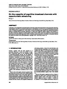
rate is achieved by letting β1 = β2 and α1 = α2 . Thus we have the following theorem. Theorem 6: For the symmetric Gaussian case, when max ≥ R ≥ R∗ , where RA A A 2P + 2mN + N0 1 ∗ max , 1 log P + Neff RA , log , RA 4 2mN + N0 2 Neff RP (RA ) =
max α∈[0,1]:RA ≤ 14 log
2αP +Neff Neff
1−α m−1 P
+N
N
.
∗ On the other hand when 0 ≤ RA ≤ RA , then RP (RA ) !m−1 1−α 1 γP + N m−1 P + N = max log , 2 N N α∈[0,1]: RA ≤ 14
log
2αP +Neff 2γP +Neff
25 20 15 10 5 0
0
0.2
0.4
0.6
0.8
1
1.2
1.4
RA
Fig. 5. Tradeoff between the auxiliary and main channel rates for m = 32, P = 10m, N1 = N2 = N0 = 1.
where (1 − α)N0 − 2(mα − 1)N . 2(mα − 1)P + (m − 1)N0 A typical tradeoff is given in Fig. 5, where the thick blue line is RP (RA ), and the red dashed line is by keeping β = 0 ∗ and varying α, which coincides with RP (RA ) above RA (red circle), i.e., the m-th sub-channel is not used by the main messages in the optimal scheme; the dotted lines are the traces when keeping α constant and varying β in Theorem 4. γ=
C. Proof of Theorem 5 We only provide an outline due to space constraint. Let P1,j be the power Pmof used on sub-channel i for the first transmitter, and thus i=1 P1,j ≤ P1 . It is straightforward to see the following inequalities nRM1 ≤ I(M1 ; Y1mn |A1 ) + n�n ≤ h(Y1mn |A1 ) − h(Y1mn |A1 , M1 , X1mn ) + n�n
from which (12) follows straighforwardly. VI. C ONCLUDING R EMARKS The model we consider, which is a Gaussian channel with no constraints on the modulation signal alphabet, is an approximation to the system studied in [6], while the system in [6] assumes that the modulation alphabet is binary. Also, while the Gaussian noise approximation is a good one for normal operating regimes for practical systems, the noise model in [6] included a cross-modulation term which has been neglected here. Whether the improvements suggested by our information theoretical analysis are worth pursuing will ultimately depend on a careful cost-benefit analysis and are more likely to be of practical value if a larger fraction of coordinates were to be used for sending auxiliary data. R EFERENCES
= h(Y1mn |A1 ) − (nm/2) log 2πeN1 + n�n mn n n log 2πeN1 + n�n . ≤ h(Y1,m |A1 ) + h(Y1,1:m−1 )− 2 It is clear that m−1 X n n h(Y1,1:m−1 )≤ log (2πe (P1,i + N1 )) 2 i=1 !! Pm−1 (a) n(m − 1) i=1 P1,i log 2πe + N1 , (14) ≤ 2 m−1 where (a) is due to the concavity of the log(·) function. It is also clear that n n n log 2πeN1 ≤ h(Y1,m |A1 ) ≤ log 2πe(P1,m + N1 ) (15) 2 2 and thus for some β1 in the interval [0, 1] n n h(Y1,m |A1 ) = log 2πe(β1 P1,m + N1 ) (16) 2 which gives the bound in (13) by defining α1 = P1,m /P1 (the bound for RM2 can be similarly derived). Using a conditional version of the entropy-power inequality [2], we write n n n n 2 2 2 2 e n h(Y0 |A1 ,A2 ) ≥ e n h(Y1,m |A1 ) + e n h(Y2,m |A2 ) + e n h(Z0 ) = 2πe(β1 P1,m + β2 P2,m + N1 + N2 + N0 ),
30
Rm
m−1 log 2
35
(17)
[1] H. Chung, S. Shin, K. Park, H. Woo, and Y. Chung, “Transmission capacity of optical path overhead transfer scheme using pilot tone for optical path network,” IEEE Photonics Technol. Lett, vol. 12, no. 6, pp. 731–733, 2002. [2] T. Cover, J. Thomas, and J. Wiley, Elements of information theory. Wiley Online Library, 1991, vol. 1. [3] M. D. Feuer and V. A. Vaishampayan, “Rejection of interlabel crosstalk in a digital lightpath labeling system with low-cost all-wavelength receivers,” IEEE Journal of Lightwave Technology, vol. 24, no. 3, pp. 1121–1128, March 2006. [4] M. Feuer, C. Hruska, H. Wang, L. Spiekman, B. Stefanov, and V. Vaishampayan, “All-optical swapping of digital lightpath labels,” in Optical Fiber communication/National Fiber Optic Engineers Conference, 2008. OFC/NFOEC 2008. Conference on. IEEE, 2008, pp. 1–3. [5] M. Feuer, V. Vaishampayan, V. Mikhailov, and P. Westbrook, “Digital lightpath label transcoding for dual-polarization qpsk systems,” in Proceedings OFC (to appear), 2011. [6] M. Feuer and V. Vaishampayan, “In-band management channel for lightpaths in photonic networks,” Tech. Dig. of ECOC2004, paper Tu3, vol. 6, 2004. [7] K. Park, S. Shin, and Y. Chung, “Simple monitoring technique for WDM networks,” Electronics Letters, vol. 35, no. 5, pp. 415–417, 2002. [8] V. A. Vaishampayan and M. D. Feuer, “An overlay architecture for managing lightpaths in optically routed networks,” vol. 53, no. 10, pp. 1729–1737, Oct. 2005. [9] L. Venturino, V. Vaishampayan, M. Feuer, and X. Wang, “Performance analysis of an asynchronous multi-user communication system for optical networks,” in Information Theory Proceedings (ISIT), 2010 IEEE International Symposium on. IEEE, 2010, pp. 2043–2047.