18
IEEE JOURNAL OF OCEANIC ENGINEERING, VOL. 41, NO. 1, JANUARY 2016
Optical Detector Array Design for Navigational Feedback Between Unmanned Underwater Vehicles (UUVs) Firat Eren, Student Member, IEEE, Shachak Pe'eri, Yuri Rzhanov, Member, IEEE, May-Win Thein, Member, IEEE, and Barbaros Celikkol
Abstract—Designs for an optical sensor detector array for use in autonomous control of unmanned underwater vehicles (UUVs), or between UUVs and docking station, are studied in this paper. Here, various optical detector arrays are designed for the purpose of determining and distinguishing relative 5 degrees-of-freedom (DOF) motion between UUVs: 3-DOF translation and 2-DOF rotation (pitch and yaw). In this paper, a numerically based simulator is developed to evaluate varying detector array designs. The simulator includes a single light source as a guiding beacon for a variety of UUV motion types. The output images of the light field intersecting the detector array are calculated based on detector hardware characteristics, the optical properties of water, and expected noise sources. Using the simulator, the performance of planar and curved detector array designs (of varying size arrays) are analytically compared and evaluated. Output images are validated using empirical in situ measurements conducted in underwater facilities at the University of New Hampshire, Durham, NH, USA. Results of this study show that the optical detector array is able to distinguish relative 5-DOF motion with respect to the simulator light source. Furthermore, tests confirm that the proposed detector array design is able to distinguish positional changes of 0.2 m and rotational changes of 10 within 4–8 m range in x-axis based on given output images. Index Terms—Light attenuation, optical communication, optical detector design, simulation, unmanned underwater vehicle (UUV), water clarity.
I. INTRODUCTION
U
NMANNED UNDERWATER VEHICLES (UUVs) are used for tasks that are difficult or too dangerous for divers, such as underwater pipeline inspection, bathymetry exploration and military operations (e.g., minesweeping, harbor monitoring, and anti-submarine warfare) [1]–[5]. Some underwater operations require more than one UUV for efficient task completion (e.g., large area surveying). The time and cost associated with Manuscript received March 19, 2014; revised September 02, 2014; accepted December 11, 2014. Date of publication January 26, 2015; date of current version January 11, 2016. This work was supported by the LINK Foundation Fellowship for Ocean Engineering and the University of New Hampshire Leslie Hubbard Marine Program Endowment. Associate Editor: J. Jaffe. F. Eren, M.-W. Thein, and B. Celikkol are with the Department of Mechanical Engineering, University of New Hampshire, Durham, NH 03824 USA (e-mail: fi
[email protected];
[email protected];
[email protected]). S. Pe'eri and Y. Rzhanov are with the Center for Coastal and Ocean Mapping/Joint Hydrographic Center, Jere A. Chase Ocean Engineering Laboratory, Durham, NH 03824 USA (e-mail:
[email protected]; yuri.rzhanov@unh. edu). Digital Object Identifier 10.1109/JOE.2015.2389592
using a single UUV are not suitable for such applications. One approach to reduce operation time is the deployment of multiple UUVs that can perform tasks while in formation. A key requirement for this group of UUVs to move in a controlled formation is an underwater communication link between the UUVs [6], [7]. In addition to UUV operation in formation, underwater communication links can also be used for UUV docking or data transfer from an operating UUV to a data storage platform [8]. The two latter applications allow UUVs to operate with longer periods underwater without the need for excessive emerging/ submerging. Most studies on intercommunication between UUVs have concentrated on acoustic communication that performs well over long distances [9]. However, the necessary hardware is costly and requires payload considerations in the UUV platform design. A cost-effective alternative is optical detection that either uses existing hardware (e.g., light sources as beacons) or additional hardware, i.e., low cost, commercially available off the shelf photo detectors, etc. In astronautical and aeronautical applications, optical communications are used for navigation, docking and data transfer [10], [11]. For example, free space optical communication is used in rendezvous radar antenna systems [12]. In both cases of interspacecraft rendezvous and docking, a continuous-wave laser is transmitted from the pursuer spacecraft to a target spacecraft or to aid in the docking process [13]. The challenge to conduct underwater optical communication is that light is significantly more scattered and absorbed in water than it is in air. As a result, the communication ranges are much more limited underwater [14]. In addition, water as a medium is rarely homogeneous and is constantly changing. Thus, it becomes difficult to predict its optical properties for varying water conditions (e.g., diffuse attenuation coefficient and scattering) during UUV operation. Detector arrays consisting of individual optical detector elements are used for pose detection between UUVs. Many possible geometric shapes for optical detector arrays exist, but the two most common array designs in literature are planar and curved [15], [16], each design having its own benefits. A planararray design can maximize the signal-to-noise ratio between all its elements, while curved arrays require a smaller number of optical elements and results in a larger field of view. Currently, studies that have investigated optical communication for UUVs are very limited and focus mainly on planar arrays for autonomous underwater vehicles (AUVs). These studies include
0364-9059 © 2015 IEEE. Personal use is permitted, but republication/redistribution requires IEEE permission. See http://www.ieee.org/publications_standards/publications/rights/index.html for more information.
EREN et al.: OPTICAL DETECTOR ARRAY DESIGN FOR NAVIGATIONAL FEEDBACK BETWEEN UNMANNED UNDERWATER VEHICLES (UUVS)
an estimation of AUV orientation to a beacon by using a photodiode array [17] and distance measurement between two UUVs [18], [19]. In addition to array designs for communication between UUVs, other studies have investigated optical communications for docking operations. For example, a single detector (quadrant photodiode) has been used to operate as a 2 2 detector array [20]. In addition, researchers have mounted an optical detector on an AUV to detect translational motion of the AUV with respect to a light source. Optical communication for distance sensing between a swarm of UUVs was conducted using a LED transceiver with an IrDA encoder/decoder chip [21]. In addition to navigation purposes, the use of optical communication has been investigated for transmitting remote control commands [22], [23] and data transfer rates [24]–[27]. Results based on laboratory and field work showed that an optical modem system consisting of an omnidirectional light source and photomultiplier tube can achieve a data streaming rate of up to 10 Mbit/s, with a reported 1.2 Mbit/s data transfer rate up to 30 m underwater in clear water conditions [26]. Other studies utilized underwater sensor network consisting of static and mobile nodes for high-speed optical communication system, where a point-to-point node communication is proposed for data muling [27]. The underwater optical communication methods mentioned above are shown to be able to measure only up to three degrees of freedom (DOF), as opposed to the UUV's full maneuvering capabilities in all six DOF. Multiple DOF motion is necessary to determine the relative orientation between two or more UUVs or between a UUV and a docking platform. Therefore, the design of an optical detector array for such an application becomes crucial. This paper compares planar and curved array designs for underwater optical detection between UUVs or between a UUV and a docking station. The comparison between the two types of arrays is conducted using a simulator that models a single-beam light field pattern for a variety of motion types (i.e., 3-DOF translation and 2-DOF rotation). In addition, the number of elements in the array and the possible noise sources from experimental hardware and the environment are also taken into account. The results from the simulator are validated using in situ measurements conducted in underwater facilities at the University of New Hampshire. The results of this study are to be used for the design of an optical detector unit for UUVs and the development of translational and rotational detection and control algorithms. The performance criteria for an optical detector array design suitable for underwater communication between UUVs can be judged by two characteristics. The first is the ability of the detector array to provide a unique signature, that is, a sampled image that represents a given location and orientation of a UUV with respect to a transmitter (i.e., light source). The second characteristic is the minimum number of required optical detector components. This characteristic is derived from the fact that a UUV should have a timely response to fast changes of the UUV's dynamics. (A smaller number of detectors would simplify the hardware design and reduce processing time. A unique signature, an image footprint from the optical detectors, would enable a UUV to receive the necessary feedback to help the
19
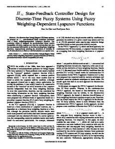
Fig. 1. Schematic illustration of array designs used in the simulator: (a) Planar array and (b) Curved array.
on-board control system to determine appropriate control commands to maintain a specified/desired orientation with respect to and distance from a beacon (or any other object of interest). II. OPTICAL DESIGN CONSIDERATIONS The idea behind an optical detector array is such that as the array, which is mounted on a UUV, comes in contact with (without loss of generality) a guiding beam, the light field is sampled and a signature of the light beam can be obtained. Here, the light source represents a guide that is mounted on a leader UUV or on a docking station. In this study, a single light source is used as the guiding beam for the detector array. The light field generated from the light source is approximated as a Gaussian beam at a given solid angle. For large arrays (i.e., arrays with several individual detectors), the light signature can be further represented as an image. The design considerations for an optical detector array can be categorized as environmental and hardware-related. In this research, the primary hardware for such a module consists of optoelectronic array components (e.g., photodiodes). These components are framed in a specific configuration and are mounted to an appropriate area on a UUV. A planar array is an array of optical detectors that are mounted on a flat, 2-dimensional frame. Although the optical detectors can be placed in any configuration, a traditional equidistant design is assumed (without loss of generality) for the sake of simplicity. The detector, furthermore, is assumed to be square, having an equal number of vertical and horizontal elements [see Fig. 1(a)]. The planar array simplifies the design and the resulting light signature, which is a cross-sectional (and possibly rotated) view of and within the light field. A curved array is an array of optical detectors that are mounted on either a spherical or parabolic frame. The geometry of the frame (curvature and oblateness) provides a larger range of incidence angles between the detectors and the light field. In this study, all elements of the curved array are equidistant in a plane projection and located at a fixed distance from the geometric center of the frame [see Fig. 1(b)]. A. Environmental Considerations The light source in this study is assumed to be a point source with peak radiance [W/m sr nm] for a given detector with a fixed aperture area and a spectral range of . Using a cylindrical coordinate system, the axial distance from the light source to the optical element along the beam axis
20
IEEE JOURNAL OF OCEANIC ENGINEERING, VOL. 41, NO. 1, JANUARY 2016
is defined as and the radial distance from the beam axis is defined as . Assuming that light is not absorbed or scattered by the water medium, radiance collected by a detector is inversely proportional to the square of the distance to the source. The location for half the peak intensity from the light source, , along the beam axis is assumed to be relatively small. The radiance from the light source according to the inverse-square law can be defined as (1) Alternatively, the radiance change from one location, , to a second location, , along the beam axis can be expressed using (2) The beam pattern produced from the intersection of a Gaussian beam light field with a plane that is perpendicular to the transmission direction can be described using a Gaussian function. Traditionally, the beam pattern is described using length terms with the peak intensity value at the intersection point of the beam axis with the plane [28] (3) is the radial distance of the beam width on the where, plane at a beam intensity of of the peak value at a distance r from the light source. For this study, a description of the beam pattern angular terms was applied with a relationship: , where is the angle between the beam axis and the light ray reaching the detector. In addition, the RMS width of intensity distribution, which is half of the beam width, , was also converted to an angular relationship: . Using a small-angle approximation, the exponent term can be defined as (4) Light in water is also attenuated by absorption and scattering. Environmental background noise, denoted by , from scattering of light in the water column may occur. This attenuation can be described using Beer's law [29], which states that radiance decreases exponentially through the medium as a function of distance, , from the source and the diffuse attenuation coefficient, . The attenuated radiance at each detector is
(5) The environmental background noise caused by interaction between the light beam and the water medium has been previously modeled. These studies that have investigated the interaction of light beams through turbulent medium (e.g., [30]–[32])
approximate the background noise using a blurring function applied to the light beam. In this study, the background noise is modeled using a Hanning window
(6) denotes the size of the Hanning window and is where, the sample number in the window, i.e., . The Hanning window is convolved with the output image generated by the optical elements. B. Hardware Considerations As light interacts with a detector element (e.g., photodiode) in the array, photons from the light are absorbed by the detector and current is generated. The current is then manipulated by the signal conditioning circuitry into a digital signal using an analog-to-digital convertor (ADC) [33]. The electrical signal measured by the detector is dependent on the intensity (i.e., the optical power) of the light beam and on the detector's responsivity (i.e., the electrical output of a detector for a given optical input). Also, noise sources produced in the hardware can make it difficult to extract useful information from the signal. The quality of the detector is characterized by the sensitivity that specifies the minimum intensity value that can be detected. The key hardware noise sources are: signal shot noise, , background shot noise, , dark-current shot noise, , Johnson noise, , amplifier noise, , and ADC-generated quantization noise, . All sources of hardware noise are assumed to be mutually independent. Furthermore, the authors assume that all noise can be approximated as Gaussian with corresponding values of standard deviation. Accordingly, these noise sources may be combined as a root sum of squares and represented with a net noise current (7) In addition to the electro-optical characteristics of the array component, the geometrical design of the array also affects the received intensity of the light signal. The incidence angle, , of the light ray reduces the level of radiance measured by the detector according to Lambert's cosine law (8) where
is the radiance at the surface normal. III. THE SIMULATOR
Based on the hardware and environmental considerations, a simulator (an analytical test bed) is developed. The goal of the simulator is to analyze varying array designs for UUV optical detection of relative translation and rotation with respect to a reference coordinate frame. The criteria in evaluating the effectiveness of a detector array design includes: 1) determining the minimum number of detector elements required for robust UUV position and attitude determination; and 2) verifying that the detector is able to acquire a unique signature for each UUV
EREN et al.: OPTICAL DETECTOR ARRAY DESIGN FOR NAVIGATIONAL FEEDBACK BETWEEN UNMANNED UNDERWATER VEHICLES (UUVS)
position/orientation combination with respect to the given light source. The simulator calculates light intensities at the individual optical elements based on the relative geometry between the light source and the detector. The simulator also takes into account the environmental and hardware effects described in the previous section. The effective operational distance for underwater communication is dependent on water clarity. Although a broad spectral range of light (400 to 700 nm) can be used for optical communication, the radiation calculation in the simulator uses a narrower spectral range (between 500 and 550 nm), providing maximum transmittance in clear to moderately clear waters. Based on empirical measurements using a 400 W metal halide lamp [34] and a commercial grade Mounted Silicon Photodiode photodetector, a maximum operational distance of up to 20 m is assumed for extremely clear waters, which represents open ocean conditions ( m ), and up to 8 m for moderately clear waters, which represents tropical coastal waters ( m ). Although the simulator can provide results for larger angles, pitch and roll angles are limited to within 20 . This constraint is based on the assumption that most UUVs are built to be stable about their pitch and roll axes of rotation, e.g., [36]–[38]. A. Reference Frame In the simulator, an Earth-fixed reference frame is assumed, where a light source is centered at the origin (0, 0, 0). Several coordinates are identified in the x–y–z coordinate frame with respect to the UUV center of mass (COM). Several attitude orientations are also identified with respect to the Earth-fixed reference frame and defined by angles , and for roll, pitch, and yaw, respectively. To ensure appropriate sensor feedback for adequate control performance [18], the detector array should be able to detect a unique light signal (pattern) for each combination of coordinate position and attitude orientation. Furthermore, this detection should be accurate to within 0.2 m of the true COM coordinate position and within 10 of the true attitude orientation within 4–8 m range in x-axis. The array geometry is chosen based upon the dimensions of the UUV. The UUV in this study is assumed to be a rigid body of box-type shape with a width (starboard to port) and height (top to bottom) of 0.4 m and a length (from bow to stern) of 0.8 m, the size of a generic observation-class ROV used as a test platform at the University of New Hampshire underwater facilities. Accordingly, the width and height of the detector array are 0.4 0.4 m for both planar and curved array designs. The adapted coordinate axes convention is that of the Tait-Bryan angles [39]. Here, the x-axis points toward the bow and the y-axis towards starboard. The body-fixed -axis points downward and completes the orthogonal triad. In this study, the follower is assumed to undergo rotation about all three-axes, i.e., pitch, roll and yaw. The coordinates associated with the array detectors are multiplied with the rotation matrices to be in the same reference system as the leader UUV. B. Array Geometry As previously mentioned, two array shapes are compared in this study: 1) a planar array; and 2) a curved array. The geometry of both arrays is defined in this section.
21
In the planar detector array, the detectors are defined relative to the UUV COM with respect to the local (body) coordinate frame. The center and the four corners of the planar array frame are defined as follows: (9.1) (9.2) (9.3) where and , respectively, define the and coordinates of the follower COM, is the length of the UUV, and and denote the width and the height of the vehicle, respectively. The lateral and vertical spacing (denoted as and ,) between the individual detectors on the array can be expressed as (10.1) (10.2) square where It is assumed that the detector array is an is the number of optical elements. That is, the number of detectors in the rows and columns of the array are the same. Accordingly, the detector spacing is also the same (i.e., ). It is important to note that for a curved array, and are projected detector spacing. A hemispherical shape is used for the curved array. The number of detectors in the curved array is initially defined based on the planar array design. Then, if the detectors are projected onto the hemispheric surface, as in Fig. 1(b), with a fixed radius (11) where is the position of the detector element on the -axis and and are the coordinates of the array that is projected onto the bow of the follower UUV. and are the indices that represent the row and column number of the array,. In this study, the radius, , of the hemisphere (of the curved array) is 0.32 m and is defined from its focal point, , which is the center of the hemisphere (12.1) (12.2) (12.3) The main difference between the planar and curved array designs is that all of the optical elements in the planar array are oriented in the same direction, while the detectors in the curved array are normal to the surface of the array frame and thus allow a larger range of incidence angles. C. Radiometry The construction of a realistic light field (as measured by the array detectors) is based on the radiometric and hardware considerations for each detector (Section II). The radiometric calculations are based on the distance (i.e., inverse square law and
22
IEEE JOURNAL OF OCEANIC ENGINEERING, VOL. 41, NO. 1, JANUARY 2016
Beer's law) and orientation (Lambert's cosine law) of each detector with respect to the light source. Using the detector's characteristics and the associated electronics, the artificially created incident light is numerically converted into a digital signal. For the array simulator in this study, the specifications of two types of photodiodes are used as reference (Thorlabs SM05PD1A, Thorlabs SM05PD2A). The resulting electronic signal is represented as a 10-bit (0–1023) sensor output value (thus, introducing quantization error). Environmental background noise is artificially added to the signal using a Hanning window of size . Also, a random net noise current of is added to the electronic signal. The final digital signal is used to generate an image pattern which, in turn, is to be used by the array detectors to identify the position and the orientation of the UUV. IV. RESULTS A. Simulator Results The success of the simulator described in this study relies on the ability of the array to provide a unique image for every UUV position/orientation combination. To process the simulator output images more efficiently, the output data is reduced to a few key image parameters, allowing for a multiparameter comparison. These chosen few parameters describe the beam pattern and allow the use of simple algorithms that do not require significant computational effort. One such algorithm is the Spectral Angle Mapper (SAM) [40], which is the dot product between sets of key parameters extracted from two images that are represented as vectors, and
Fig. 2. Key image parameters and intensity profiles for a planar array detector unit with hardware and environmental background noise: (top left) Output image from the simulator, (top right) Horizontal profile, (bottom left) Vertical profile, (bottom right) Input values used to generate output image and key parameters describing output image.
(13) The calculated angle between the two vectors, i.e., SAM angle , is the numerical resemblance between the images. Two very similar images result in an angle value close to 0 , whereas two very different images result in an angle close to 90 . The SAM angle provides a good performance evaluation indicator to the different types of array detector geometries tested using a singlevalue parameter. Although the UUV is a six DOF system, it is assumed that it is not possible to achieve relative roll angle detection (because of axial symmetry about the body -axis). Thus, only five parameters are provided to the simulator as input: translation along all three coordinate axes, rotation of the pitch angle, , and rotation of the yaw angle, . Accordingly, the image output of the simulator is analyzed using five parameters that can be related to input parameters (see Fig. 2): the peak light intensity value, , the corresponding location of the horizontal detector, , and vertical detector, , at peak intensity, the location of the skewness of the horizontal intensity profile gradient, , and skewness of the vertical intensity profile gradient, . The peak value is normalized with respect to a given maximum detectable intensity . The locations of the horizontal and vertical detectors are defined with respect to the central detector . Based on the location of the peak
Fig. 3. Key image parameters and intensity profiles for a curved array detector unit with hardware and environmental background noise: (top left) Output image from the simulator, (top right) Horizontal profile, (bottom left) Vertical profile, (bottom right) Input values used to generate output image and key parameters describing output image.
intensity, the slopes of the horizontal and vertical intensity are calculated. The slope of the profile is used rather than the profile itself as the slope also provides the directionality of the beam profile (i.e., negative or positive) in addition to the asymmetry of the profile. The images and the corresponding parameters for the planar and the curved array of size 21 21 for a given coordinate location and yaw rotation are shown in Figs. 2 and 3, respectively. B. Detector Array Comparison As a first step for the selection of the array design, the geometry of the detector array is evaluated. A performance evaluation
EREN et al.: OPTICAL DETECTOR ARRAY DESIGN FOR NAVIGATIONAL FEEDBACK BETWEEN UNMANNED UNDERWATER VEHICLES (UUVS)
23
Fig. 5. Comparative resemblance results (i.e., SAM angle) with respect to varying array sizes (incorporating environmental and background noise): (a) SAM angle with respect to lateral motion (b) SAM angle with respect to angular rotation. Fig. 4. Comparative resemblance results (SAM angles) for 21 21 element m) as a function of: (a) lateral translation, (b) curved and planar array (at yaw rotation.
between planar and curved arrays is conducted, where each detector array contains a 21 21 grid of detector elements with a detector spacing of 0.02 m. Both detector arrays are evaluated for their ability to detect changes in position and orientation, i.e., changes in SAM angle, . Changes in position are evaluated as the UUV translates along the y-axis from a given origin (0 m) to an offset of 0.9 m in 0.03 m increments. Similarly, changes in orientation are evaluated by rotating the UUV about the z-axis, yaw rotation, from its initial reference (0 ) to 30 in increments of 1 . Fig. 4 represents the resemblance results to identify UUV positional and attitude changes based on measured signals (images) collected by the detector array at 4 m. The comparative results for changes in position using the SAM algorithm show similar performance between the two array geometries, where the curved array performs slightly better (2 ) at shifts greater than 0.6 m. However, an investigation of the results for changes in orientation reveals that the curved array is more sensitive to changes in orientation than the planar array. The SAM angle results for the curved array show changes of 12 at 5 yaw rotations and changes of 22 at 10 rotations, whereas the results for the planar array show changes in SAM angle of 5 at 5 yaw rotations and 11 at 10 rotations. Based on these results, it is deduced that the curved array geometry is more suitable for distinguishing changes in position and, especially, orientation of a UUV platform with respect to a reference light beacon. After the geometry of the detector array is defined, relationships between the ability to distinguish changes in position and orientation from the output images and the number of elements in the curved detector array are evaluated. The comparisons include different array sizes, ranging from a 3 3 size array up to a 101 101 size array at distances ranging from 4 m to 8 m to the light source. The comparative results at 4 m (see Fig. 5) show that changes in positional and rotational shifts can be detected by an array with the size of at least 5 5 optical elements
Fig. 6. Comparative resemblance results (i.e., SAM angle) with respect to operational distance (incorporating environmental and background noise): (a)–(c) lateral shift, (d)–(f) yaw rotation - (a), (d) 3 3 array (b), (e) 5 5 array (c), (f) 101 101 array with spacing of 0.2 m, 0.1 m and 0.004 m, respectively.
with detector spacing of 0.1 m. Based on a threshold of a 15 SAM angle, a smaller array would fail to detect translational shifts smaller than 0.2 m or rotational changes smaller than 10 . It should also be noted that no significant changes in detection capability are observed for array sizes greater than 7 7 with a detector spacing of 0.067 m. The effect of operational distances greater than 4 m is shown in Fig. 6. Although the ability of the curved array to distinguish between the images decreases as the operational distance increases, the SAM algorithm results for 5 5 array at 8 m are still above 10 for a 10 yaw rotation and above 6 for 0.2 m translation. C. Experimental Confirmation In addition to the analytical study presented in this paper, experimental validations are conducted at the University of New Hampshire's underwater facilities. The underwater experiments
24
IEEE JOURNAL OF OCEANIC ENGINEERING, VOL. 41, NO. 1, JANUARY 2016
Fig. 7. Comparison of experimental and simulation results: (a) 4 m; (b) 5 m; (c) 6 m; (d) 7 m; and (e) 8 m.
compare the simulator outputs to that of empirical measurements. This comparison validates the optical model used in the simulator (i.e., Gaussian beam profile) and confirms the environmental physical properties that contribute to the light field as received by the detector array. The light source in this study is a 400 W underwater halogen lamp (contained in a waterproof fixture). Profiles of light intensity data (radiance measurements) were collected via a spectrometer such that the measurements are perpendicular to that of the illumination axis. The profiles are collected at distances ranging from 4 m to 8 m at 1 m increments and with lateral shifts from the illumination axis up to 1 m away from the axis at 0.1 m increments. The profiles from empirical measurements are compared to profiles produced from simulator output images calculated for the same distance and orientation conditions (see Fig. 7). The measured profiles confirm that the light field calculations for the simulations are valid. Although the background noise in the simulated models is overestimated, the correlation, , between the two profiles is between 0.95–0.99 for distances from 4–8 m. V. DISCUSSION The results of this study show that the detector array simulator is a useful and reliable tool for array design in optical communication between UUVs or between a UUV and a docking station. The simulator has a modular design to allow for the addition and changing of hardware and environmental parameters. Although the simulator can evaluate other array geometries with a variety of sizes, only two traditional shapes are considered. The simulator results show that a curved array with a minimum array size of 5 5 elements is sufficient for distinguishing positional changes of 0.2 m and rotational changes of 10 . For the distinction of smaller changes, a larger array size is required. A follower UUV is assumed to have five DOF maneuverability with respect to a given light source: three DOF translations (i.e., translations along the , and axes) and two DOF rotations (yaw and pitch). Because the transmitter unit in the presented configuration has only one light source with
a Gaussian spatial intensity distribution, it is not possible to decouple roll changes (rotation about the body-fixed -axis) from either pitch or yaw. This is due to the axial symmetry of the light beam. The use of multiple light sources or a light source with a unique intensity distribution may enable roll rotation sensing. It is important to note that the simulator assumes that the water column is uniform with systematic background noise. As a result, the output images of the light field intersecting with the detector array resemblance a Gaussian beam pattern. However, disturbances in the medium (e.g., sediment plume) may cause the beam pattern to be distorted. This point should be taken into account in the development of control algorithms for UUV navigation. Otherwise, the control algorithms may misinterpret the acquired image and direct the follower UUV away from the guiding beam. The simulator results show that detector noise does not contribute significantly to the image output. Other detectors with a larger noise level may contribute more to output images. An alternative hardware component that was considered instead of photodetectors was a camera array. The potential benefits using COTS cameras (CCD or CMOS) is to provide additional spatial information that can potentially enhance the performance of pose detection algorithms. However, one of the requirements for an autonomous system is the ability to process the sensor's input and execute the pose detection algorithms fast enough to respond to changes in the UUV's dynamics (i.e., detection of the leader UUV and a response by the follower UUV). It seems that a camera array that performs image extraction and processing procedures may not be sufficiently fast for the UUV interaction. With that said, the camera array option will be considered for future work that allows slower update rates of pose detection algorithms. VI. CONCLUSION In this paper, a detector array simulator was developed to evaluate different geometrical structures of optical arrays of varying sizes for underwater position/orientation detection between UUVs or between a UUV and a docking station. Criteria for an array design suitable in underwater communication between UUVs were based on: 1) the ability of the array to distinguish changes in position and orientation of a UUV with respect to a given light source; and 2) the minimum number of optical detector components that would simplify the hardware design and reduce processing time. The simulator calculated a light field generated from a single light source passing through the water column, taking into account attenuation and scattering. Based on the optoelectronic characteristics of the detectors (including noise) and the array design, an output image of the light field intersecting the detector array was produced. Two array designs, i.e., planar and curved, were evaluated based on their ability to distinguish changes in position and orientation between the UUV and a guiding light source. Because of the beam pattern symmetry (generated from a single light source), it is possible to detect 5-DOF UUV motion, i.e., translations along and -axes, as well as pitch and yaw rotations, and not full 6-DOF motion. The input data in the simulator evaluation included the relative geometry between the light source and the optical array. The SAM algorithm evaluated the detector
EREN et al.: OPTICAL DETECTOR ARRAY DESIGN FOR NAVIGATIONAL FEEDBACK BETWEEN UNMANNED UNDERWATER VEHICLES (UUVS)
array design and was able to distinguish translational changes within an operational range between 4 m to 8 m with accuracy of 0.2 m and rotational shifts within 10 using key output image parameter values. Using a 21 21 array with detector spacing of 0.02 m, it was determined that a curved array design is more sensitive to rotational changes than a planar array, whereas both array geometries performed similarly for translational shifts. After the geometry of the detector array was defined, the minimum number of element in the detector array was determined. The simulator results showed that an array of at least 5 5 detector elements with 0.1 m detector spacing was needed to distinguish changes in five DOF. The results were also validated using in situ experimental measurements.
REFERENCES [1] H. J. Curti, G. G. Acosta, and O. A. Calvo, “Autonomous underwater pipeline inspection in autotracker project: The simulation module,” in Proc. IEEE/OCEANS'05 Eur. Conf., Brest, France, Jun. 21–23, 2005, vol. 1, pp. 384–388, DOI: 10.1109/OCEANSE.2005.1511745. [2] G. Inglis, C. Smart, I. Vaughn, and C. Roman, “A pipeline for structured light bathymetric mapping,” in Proc. Int. Conf. Intell. Robots Syst. (IROS), Vilamoura, Algarve, Portugal, Oct. 7–12, 2012, pp. 4425–4432, DOI: 10.1109/IROS.2012.6386038. [3] D. B. Edwards, T. A. Bean, D. L. Odell, and M. J. Anderson, “A leaderfollower algorithm for multiple AUV formations,” in Proc. IEEE/OES Autonom. Underwater Veh., Sebasco, ME, USA, Jun. 17–18, 2004, pp. 517–523, DOI: 10.1109/AUV.2004.1431191. [4] J. Jalbert, J. Baker, J. Duchesney, P. Pietryka, W. Dalton, D. R. Blidberg, S. Chappell, R. Nitzel, and K. Holappa, “A solar-powered autonomous underwater vehicle,” in Proc. OCEANS, Sep. 22–26, 2003, vol. 2, pp. 1132–1140. [5] M. Hamilton, S. Kemna, and D. T. Hughes, “Antisubmarine warfare applications for autonomous underwater vehicles: The GLINT09 field trial results,” J. Field Robot., vol. 27, no. 6, pp. 890–902, 2010. [6] S. Willcox, D. Goldberg, J. Vaganay, and J. Curcio, “Multi-vehicle cooperative navigation and autonomy with the bluefin CADRE system,” in Proc. Int. Fed. Autom. Contr. Conf. (IFAC-06), Lisbon, Portugal, Sept. 20–22, 2006. [7] J. Curcio, J. Leonard, J. Vaganay, A. Patrikalakis, A. Bahr, D. Battle, H. Schmidt, and M. Grund, “Experiments in moving baseline navigation using autonomous surface craft,” in Proc. OCEANS MTS/IEEE, Washington, D.C., USA, Sep. 18–23, 2005, vol. 1, pp. 730–735. [8] B. W. Hobson, R. S. McEwen, J. Erickson, T. Hoover, L. McBride, F. Shane, and J. G. Bellingham, “The development and ocean testing of an AUV docking station for a 21 AUV,” in Proc. IEEE OCEANS, Vancouver, BC, Canada, Sep. 29–Oct. 4 2007, pp. 1–6, DOI: 10.1109/ OCEANS.2007.4449318. [9] E. M. Sorer, M. Stojanovic, and J. G. Proakis, “Underwater acoustic networks,” IEEE J. Ocean. Eng., vol. 25, no. 1, pp. 72–83, Jan. 2000. [10] B. G. Boone, J. R. Bruzzi, W. P. Millard, K. B. Fielhauer, B. E. Kluga, C. W. Drabenstadt, and R. S. Bokulic, “Optical communications development for spacecraft applications: Recent progress at JHU/APL,” in Proc. IEEE Aerosp. Conf., Big Sky, MT, USA, Mar. 5–12, 2005, pp. 1570–1582, DOI: 10.1109/AERO.2005.1559448. [11] E. Y. Chan, J. C. Adams, J. M. S. Clair, K. A. Morrison, and M. Sosa, “Application of COTS high-power laser diodes and driver for a freespace laser communication terminal,” in Proc. SPIE, Free-Space Laser Commun. Technol. X, San Jose, CA, USA, Jane 24, 1998, vol. 3266, pp. 54–67. [12] P. G. Goetz, W. S. Rabinovich, G. C. Gilbreath, R. Mahon, M. S. Ferraro, L. Swingen, R. J. Walters, S. R. Messenger, L. M. Wasiczko, J. Murphy, N. G. Creamer, H. R. Burris, M. F. Stell, C. I. Moore, S. C. Binari, and D. S. Katzer, “Multiple quantum well based modulating retroreflectors for inter- and intra-spacecraft communication,” in Proc. SPIE, Photon. Space Environments XI, 2006, vol. 6308. [13] L. M. Wasiczko, H. R. Burris, N. G. Creamer, R. Mahon, C. Moore, L. Swingen, J. Murphy, M. Stell, B. E. Pinney, P. Goetz, W. J. Scharpf, W. S. Rabinovich, and G. C. Gilbreath, “Optical communication and navigation for spacecraft docking using modulating retroreflectors,” in Proc. SPIE, Free-Space Laser Commun. V, 2005, vol. 5892.
25
[14] C. D. Mobley, Light and Water. New York, NY, USA: Academic Press Inc., 1994, ch. 5. [15] F. C. Ellot, “Geometric design of linear array detectors,” IEEE Trans. Electron Dev., vol. ED-21, no. 10, pp. 613–616, Oct. 1974. [16] S.-B. Rim, P. B. Catrysse, R. Dinyari, K. Huang, and P. Peumans, “The optical advantages of curved focal plane arrays,” Opt. Express, vol. 16, no. 7, pp. 4965–4971, 2008. [17] I. Vasilescu, P. Varshavskaya, K. Kotay, and D. Rus, “Autonomous modular optical underwater robot (AMOUR) design, prototype and feasibility study,” in Proc. Int. Conf. Robot. Autom.., Barcelona, Spain, Apr. 18–22, 2005, pp. 1603–1609, DOI: 10.1109/ROBOT.2005.1570343. [18] F. Eren, M. W. Thein, B. Celikkol, J. DeCew, and S. Pe'eri, “Distance detection of unmanned underwater vehicles by utilizing optical sensor feedback in a leader-follower formation,” in Proc. IEEE/MTS OCEANS, 2012, Hampton Roads, VA, USA, Oct. 14–19, 2012, pp. 1–6, DOI: 10.1109/OCEANS.2012.6404934. [19] F. Eren, S. Pe'eri, and M. W. Thein, “Characterization of optical communication in a leader-follower unmanned underwater vehicle formation,” in Proc. SPIE, Ocean Sens. Monitoring V, Baltimore, MD, USA, Apr. 30–May 1 2013, 2013, vol. 8726. [20] S. Cowen, S. Briest, and J. Dombrowski, “Underwater docking of autonomous undersea vehicles using optical terminal guidance,” in Proc. IEEE OCEANS Conf., Oct. 1997, vol. 2, pp. 1143–1147. [21] F. Schill, U. R. Zimmer, and J. Trumpf, “Visible spectrum optical communication and distance sensing for underwater applications,” in Proc. Australasian Conf. Robot. Autom., 2004, pp. 1–8. [22] M. Doniec, C. Detweiler, I. Vasilescu, and D. Rus, “Using optical communication for remote underwater robot operation,” in Proc. IEEE/RSJ Int. Conf. Intell. Robots Syst., 2010, pp. 4017–4022, DOI: 10.1109/ IROS.2010.5650224. [23] N. Farr, A. Bowen, J. Ware, C. Pontbriand, and M. Tivey, “An integrated, underwater optical/acoustic communications system,” in Proc. IEEE OCEANS Conf., 2010, pp. 1–6, DOI: 10.1109/OCEANSSYD. 2010.5603510. [24] N. Farr, A. Chave, L. Freitag, J. Preisig, S. White, D. Yoerger, and F. Sonnichsen, “Optical modem technology for seafloor observatories,” in Proc. OCEANS Conf., 2006, pp. 1–6, DOI: 0.1109/OCEANS.2006. 306806. [25] M. Doniec, M. Angermann, and D. Rus, “An end-to-end signal strength model for underwater optical communications,” IEEE J. Ocean. Eng., vol. 38, no. 4, Oct. 2013. [26] M. Doniec, I. Vasilescu, M. Chitre, C. Detweiler, M. Hoffmann-Kuhnt, and D. Rus, “AquaOptical: A Lightweight Device for High-rate Longrange Underwater Point-to-Point Communication,” in Proc. OCEANS Conf., Biloxi, MS, USA, Oct. 2009, pp. 1–6. [27] I. Vasilescu, K. Kotay, D. Rus, M. Dunbabin, and P. Corke, “Data collection, storage, and retrieval with an underwater sensor network,” in Proc. ACM SenSys., San Diego, CA, USA, Nov. 2005, pp. 154–165. [28] B. E. A. Saleh and M. C. Teich, Fundamentals of Photonics, 2nd ed. New York, NY, USA: Wiley, 2007, pp. 74–101. [29] W. D. Philpot, “Bathymetric mapping with passive multispectral imagery,” Appl. Opt., vol. 28, no. 8, pp. 1569–1578, 1989. [30] A. Elkabetz and Y. Yitzhaky, “Background modeling for moving object detection in long-distance imaging through turbulent medium,” Appl. Opt., vol. 53, no. 6, pp. 1132–1141, 2014. [31] H. T. Yura, “Small-angle scattering of light by ocean water,” Appl. Opt., vol. 10, no. 1, pp. 114–118, 1971. [32] H. T. Yura, “Propagation of finite cross-section laser beams in sea water,” Appl. Opt., vol. 12, no. 1, pp. 108–115, 1973. [33] K. J. Kasunic, Optical Systems Engineering. New York, NY, USA: McGraw-Hill, 2011, pp. 275–301. [34] S. Pe'eri and G. Shwaery, “Radiometric and photometric determinations of simulated shallow-water environment,” Int. J. Remote Sens., vol. 34, no. 18, pp. 6437–6450, 2013. [35] C. Kunz, C. Murphy, R. Camilli, H. Singh, J. Bailey, R. Eustice, M. Jakuba, K. Nakamura, C. Roman, T. Sato, R. Sohn, and C. Willis, “Deep sea underwater robotic exploration in the ice-covered arctic ocean with AUVs,” in Proc. IEEE/RSJ Int. Conf. Intell. Robots Syst. (IROS), Nice, France, Sep. 22–26, 2008, pp. 3654–3660, DOI: 10.1109/IROS.2008.4651097. [36] D. A. Smallwood and L. L. Whitcomb, “Adaptive identification of dynamically positioned underwater robotic vehicles,” IEEE Trans. Control. Syst. Technol., vol. 11, no. 4, pp. 505–515, Jul. 2003. [37] S. Negahdaripour and P. Firoozfam, “An ROV stereovision system for ship-hull inspection,” IEEE J. Ocean. Eng., vol. 31, no. 3, pp. 551–564, Jul. 2006.
26
IEEE JOURNAL OF OCEANIC ENGINEERING, VOL. 41, NO. 1, JANUARY 2016
[38] J. Diebel, “Representing attitude: Euler angles unit quaternions, and rotation vectors,” Stanford Univ., Stanford, CA, USA, 2006 [Online]. Available: http://citeseerx.ist.psu.edu/viewdoc/summary?doi=10.1.1.110.5134 [39] J. C. McGlone, “Manual of Photogrammetry,” American Society for Photogrammetry and Remote Sensing, 2004, pp. 37–45. [40] F. A. Kruse, A. B. Lefkoff, J. B. Boardman, K. B. Heidebrecht, A. T. Shapiro, P. J. Barloon, and A. F. H. Goetz, “The spectral image processing system (SIPS)—Interactive visualization and analysis of imaging spectrometer data,” Remote Sens. Environment, vol. 44, no. 2, pp. 145–163, 1993.
Firat Eren (S’11) received the B.S. degree in mechatronics engineering from Sabanci University, Istanbul, Turkey, in 2008, and the M.S. degree in mechanical engineering from the University of New Hampshire, Durham, NH, USA, in 2011 He is currently working toward the Ph.D. degree in mechanical engineering at the University of New Hampshire in Mechanical Engineering Department. His research interests include system dynamics and control, navigation, detection and control of underwater vehicles, optical systems, and communications.
Shachak Pe'eri received the B.Sc., M.Sc., and Ph.D. degrees from the Tel Aviv University, Israel, Ramat Aviv, Israel, in 1996, 1997, and 2005, respectively, all in geophysics. He is currently working as a Research Associate Professor in the Center of Coastal and Ocean Mapping, University of New Hampshire, Durham, NH, USA. His research interests include optical remote sensing in the littoral zone with a focus on experimental and theoretical studies of lidar remote sensing (airborne lidar bathymetry, topographic lidar, and terrestrial laser scanning), hyperspectral remote sensing, and sensor fusion.
Yuri Rzhanov (A’01–M’01) received the Ph.D. degree in semiconductor physics from the Russian Academy of Sciences, Saint Petersburg, Russia, in 1983. Before joining the University of New Hampshire in 2000, he had been working at the Heriott-Watt University in Edinburgh, Scotland. His research interests include optical methods of seafloor mapping, blending techniques for construction of photomosaics from imagery acquired underwater, and seabottom structure reconstruction from multiple views. He is currently a Research Professor at the Center for the Coastal and Ocean Mapping/Joint Hydrographic Center (CCOM/JHC) at the University of New Hampshire, Durham, NH, USA.
May-Win Thein (M’99) received the B.S. and M.S. degrees in mechanical engineering from Lehigh University, Bethlehem, PA, USA, in 1991 and 1992, respectively, and the Ph.D. degree in mechanical engineering from Oklahoma State University, Stillwater, OK, USA, in 1999. She became an Assistant Professor in the Department of Mechanical Engineering at the University of New Hampshire, Durham, NH, USA, in 1999, and is now currently an Associate Professor there. She has also been an Associate Professor in Ocean Engineering since 2005. Her area of research includes autonomous control of unmanned underwater vehicles (ROVs and AUVs) and autonomous surface vehicles (ASVs) and precision underwater depth control for open ocean aquaculture. Her other research includes spacecraft attitude and orbital determination and control with variable structure systems applications to nonlinear state estimation and control. Her current projects are in collaboration with NAVSEA, NEEC, ONR, NOAA, and NASA. Dr. Thein was named a United Kingdom Royal Society Fellow in 2007 and is a Member of Tau Beta Pi, Pi Tau Sigma, Phi Eta Sigma, Sigma Xi, ASME, AIAA, SWE, and SAE.
Barbaros Celikkol received the Ph.D. degree in physics from University of New Hampshire, Durham, NH, USA in 1972. His research interests include the areas of open ocean aquaculture engineering, environmental modeling, and oil spill response technology.