bypasses SQL whenever possible and uses a new latch-free ... replicating data as diverse as credit card transactions, email .... Sender. Propagation. Receiver. Fig. 3 Streams process architecture for single capture, single propagation, and.
Oracle Streams: a High Performance Implementation for Near Real Time Asynchronous Replication Lik Wong, Nimar S. Arora, Lei Gao, Thuvan Hoang, Jingwei Wu Oracle USA 500 Oracle Parkway, M/S 4op10, Redwood Shores, CA, U.S.A. {lik.wong,nimar.arora,lei.gao,thuvan.hoang,jingwei.wu}@oracle.com
Abstract— We present the architectural design and recent performance optimizations of a state of the art commercial database replication technology provided in Oracle Streams. The underlying design of Streams replication is a pipeline of components that are responsible for capturing, propagating, and applying logical change records (LCRs) from a source database to a destination database. Each LCR encapsulates a database change. The communication in this pipeline is now latch-free to increase the throughput of LCRs. In addition, the apply component now bypasses SQL whenever possible and uses a new latch-free metadata cache. We outline the algorithms behind these optimizations and quantify the replication performance improvement from each optimization. Finally, we demonstrate that these optimizations improve the replication performance by more than a factor of four and achieve replication throughput of over 20,000 LCRs per second with sub-second latency on commodity hardware.
I. INTRODUCTION Almost every digital enterprise has a compelling reason to employ some form of database replication for disaster recovery or high availability. These enterprises can be replicating data as diverse as credit card transactions, email messages, court orders, cell phone calls, or even the results of experiments on particle accelerators. However, they have almost identical requirements to replicate a high volume of transactions with low replication latency, and often involve replication over a wide area network (WAN). In fact, many non-traditional replication uses, such as online upgrade or migration of applications, have similar requirements. These stringent requirements severely restrict the replication strategies that are viable. A. Replication Strategies Replication strategies can be broadly categorized as synchronous or asynchronous. In synchronous replication, a user transaction is not allowed to commit unless it is guaranteed that it will be successfully applied on all the replicas, or a critical subset of them. This guarantee can be achieved by relying on the well known two-phase commit protocol [15], or by middleware that imposes a global order on all user transactions via an atomic broadcast service
[13][18]. In asynchronous replication, the replicated transactions on the replica databases are not coordinated with the user transactions on the source. These two categories of replication are similar to eager and lazy replication, respectively, as described in the previous literature [9]. However, the definition of eager does not allow for synchronous replication based on atomic broadcast. Also, the definition of lazy does not allow for asynchronous replication where the changes are propagated while the transaction is ongoing. We call this last form of replication streaming asynchronous replication (see Fig. 1). User transaction
Replicated transaction
User transaction
Write A
Write A
Write B
Write B
Write C
Write C
Commit
Commit
Replicated transaction Write A Write B Write C Commit
Time
Write A Write B Write C Commit Lazy
Streaming
Fig. 1 Lazy vs. streaming asynchronous replication
The advantage of synchronous replication is that it automatically handles concurrent conflicting transactions on different replica databases. The main disadvantage is that it greatly reduces the throughput of dependent transactions on each replica. The critical issue is the time period when a transaction is complete and is seeking to commit. Normally, in asynchronous replication, such a transaction writes its commit record to the redo logs, releases all locks, waits for acknowledgement from the storage system, and finally sends an acknowledgement to the user. In synchronous replication, on the other hand, the transaction must first broadcast its intention to commit to the other replicas and wait for an acknowledgement. The precise mechanics of this
communication depend on the particular implementation, but in all implementations, database locks cannot be released until the minimum time required for one network round-trip has elapsed. This network round-trip means that dependent transactions can commit no faster than the network latency permits. Asynchronous replication, on the other hand, has to reconcile conflicting transactions. Although the reconciliation procedure depends on the application, in many cases simple approaches such as maximum-timestamp work quite well in practice [9][16]. Both synchronous and asynchronous replication strategies have drawbacks, but many enterprise customers do not consider these equal. In many applications, the rate of global concurrent conflicting transactions is much lower than the rate of local concurrent conflicting transactions. As a consequence, synchronous replication is not justifiable for such applications. Lazy asynchronous replication works well for small transactions, but for a large transaction the replication latency can be unacceptably high. Streaming asynchronous replication can better handle large transactions because the replication latency is mainly determined by network latency and not transaction size. B. Oracle Streams Replication Designing streaming asynchronous replication can be challenging because it needs to handle an almost unbounded and ever-increasing transaction workload [21]. We will discuss the design of one such replication technology, Oracle Streams, and its optimizations to meet these challenges. The architecture of Oracle Streams involves three components – capture, propagation, and apply. These are responsible for capturing database changes, propagating them to a replica, and applying the database changes on the replica database, respectively. The three components are arranged in a pipeline, and they stream LCRs (Logical Change Records – a generalized form of a database change record) between them using in-memory queues1 (Fig. 2). Source database capture queue network
propagation queue
apply Replica database Fig. 2 Oracle Streams: replication components
The advantage of dividing the replication task among a number of components is that it exploits the available
concurrency on the computer systems. The disadvantage is that these components must communicate through the intermediate queues, which might become contention hot spots. In an early implementation of these queues, a latch [8] was used to serialize access. However, the latch limited concurrency and did not scale well. We present here a new, latch-free 2 implementation. Further, the enqueue operation completes in a finite number of steps if the queue is not full, and the browse completes in a finite number of steps if the queue is not empty. Hence, our implementation can be considered a wait-free [3], fixed-size queue. Our queue semantics is different from that of Herlihy et al. [10]. In our design each enqueued message is dequeued by every consumer and there is only one enqueuer. Our new queue implementation can handle tens of thousands of messages per second. In practice, however, the rate of messages is lower than the maximum limit of the queue because of two factors. First, the database changes are mined from the redo logs, and hence LCRs cannot be generated faster than the rate at which the redo can be written to disk. Second, the messages in the pipeline only flow as fast as the slowest consumer. In this regard, the performance of the apply component is most critical. Capture and propagation typically spend a fixed amount of processing time per LCR, which allows them to keep up with the redo generation rate, unless there are insufficient hardware resources, such as CPU, disk IO, or network bandwidth. Apply, on the other hand, has to un-interleave the redo stream to extract transactions that must be applied concurrently in order to keep up with the source, and at the same time must respect the dependencies of the transactions to avoid generating deadlocks [1]. In order to compensate for the extra processing requirements of apply, the apply component now bypasses the database SQL layer and uses an internal data layer API directly on tables whenever possible. Using the latch-free queue and the data layer API, Streams can replicate tens of thousands LCRs per second. Such high throughput places much more stringent demands on the replication metadata access and caching in the apply component. These demands have led to significant latch contention when multiple apply processes access the replication metadata. To eliminate such latch contention and improve the concurrency among the apply processes, we have designed a new latch-free, single-writer, shared hash table algorithm to allow latch-free access to the shared metadata cache. Our latch-free hash table is different from the published latch-free hash tables [14][19] because our latch-free hash table is single-writer, only requires the atomic read/write of a word, and does not require the atomic compare-and-swap (CAS), which is more expensive. Each hash entry in our hash table has a lifetime and can be invalidated independently due to schema evolution. The writer can safely assume that no 2
1
Unless specified otherwise, all queues discussed in this paper are in-memory queues.
We use the term latch-free instead of the usual lock-free in distributed computing literature because locks have a different meaning in database literature [8].
reader is referencing a hash entry after some point without using reference counting 3 . Instead, the apply component leverages the unique and monotonically increasing property of an LCR stream. As a result of these optimizations in Oracle Database 11g, Streams can replicate over 20,000 LCRs per second on commodity hardware. Independent analysis by a customer [7] demonstrates a more than double performance improvement. To the best of our knowledge, the highest throughput published for replication systems similar to Oracle Streams is 12,000 [11]. The rest of this paper is structured as follows. Section II provides an overview of the Oracle Streams architecture and some terminology. Section III discusses the latch-free and wait-free queue design, section IV discusses the usage of the data layer API in the apply component for bypassing the SQL layer, and section V discusses the latch-free metadata cache and invalidation in the apply component. Finally, section VI presents the performance of some unidirectional replication benchmarks using Oracle Streams. II. OVERVIEW OF ORACLE STREAMS Oracle Streams is a unified, information-sharing infrastructure that provides generalized components for the capture, propagation, and consumption of information. A full overview of the many features of Streams and its uses is beyond the scope of this paper; the interested reader is referred to Oracle Streams’ manual [17]. We limit this discussion to the data replication aspects of Streams. A. Database Change Records In Oracle Streams replication, the information that represents a change to a relational database is known as a logical change record (LCR). An LCR is a generalized representation of all possible changes to a database, and is independent of the database vendor. A change record (CR), on the other hand, is a term we use to denote a database-specific representation of a change. B. Rule The user can specify which LCRs to replicate by using a set of rules, with rule conditions that are similar to SQL WHERE clauses. These rules are evaluated against all the changes made to the database to filter out the irrelevant LCRs. C. Capture, Propagation and Apply The three components of Streams are capture, propagation, and apply. The behaviour of each component is controlled by rules: • Capture reads CRs contained in the redo generated by the database. It converts these CRs into LCRs and enqueues them. 3 A latch-free reference counting scheme [6] requires the atomic double CAS, while our latch-free hash table does not require the atomic CAS.
•
Propagation consumes LCRs from one queue and enqueues them into another queue, usually on a different database.
•
Apply consumes LCRs from a queue and performs the database change specified in the LCR. Because all database changes are recorded in the redo, apply can be thought of as writing CRs into the redo. In that sense, apply is the inverse of capture.
Fig. 3 illustrates the Oracle Streams architecture for unidirectional replication. We use this architecture to describe each of the Streams components in this subsection. By connecting appropriate components, we could configure other replication topologies. For example, we could share the capture component and add propagation and apply components to get another replica. The capture component consists of a log reader process, multiple preparer processes, a builder process, and a capture process. The log reader process reads the redo log and divides the redo log into regions. The preparer processes scan the regions defined by the log reader in parallel and perform prefiltering of changes found in the redo log based upon userdefined rules. The builder process merges redo records from the preparers and passes the merged redo records to the capture process. The capture process then formats each change into an LCR and enqueues it into a queue if it satisfies the defined rules. LCRs not grouped into transactions CR
Redo Logs at Source Database
Log Reader
Builder
Preparer
Capture
LCR LCR : Streams Pool
Propagation Sender
Capture at Source Database Propagation
Apply at Replica Database Redo Logs at Replica Database
Applier
Conflict Detection Error Handling Custom Code
Coordinator Transactions to be applied
Apply Reader
Committed transactions grouped and sorted in commit order
LCR LCR : Streams Streams PoolPool
Propagation Receiver
Fig. 3 Streams process architecture for single capture, single propagation, and single apply
The propagation component consists of one sender process at the source database and one receiver process at the replica database. The propagation sender process dequeues LCRs that satisfy the propagation rules and streams those LCRs over the network to the propagation receiver process. The propagation receiver process receives LCRs from the network and enqueues them. The apply component consists of an apply reader process, a coordinator process, and multiple applier processes. The apply reader process dequeues LCRs, assembles them into complete transactions, and passes the transactions to the coordinator. The coordinator process assigns transactions to available appliers based on the transaction dependencies and commit ordering. Each applier process executes an entire transaction
at the replica database before requesting another one. The applier processes can process independent transactions concurrently when apply parallelism is enabled. D. In-memory Staging and Recovery Oracle Streams uses queues as temporary staging areas for LCRs as they move between different Streams components and across databases. The user configures Streams by first creating the queues and then attaching various Streams components as producers to or consumers of the queues. For instance, a capture process can enqueue into a queue from which multiple propagation senders dequeue. Oracle Streams reduces performance overhead on LCR replication by staging LCRs using in-memory queues while guaranteeing no LCR loss in the presence of failures, such as system crashes, database instance crashes, or unexpected reboots. Using in-memory queues allows Oracle Streams to stage LCRs without paying the high cost of disk operations, which occurs when persistent queues are used. Using persistent queues can simplify the recovery of the replication state [5]. Once a message is enqueued into a persistent queue, the enqueuer can assume that the message will eventually arrive at the destination system. However, the disk operations in persistent queues impose significant performance overhead. Oracle Streams relies on the database redo logs to recover LCRs that are transient in the in-memory queues. During recovery, the capture component obtains the apply progress information from the apply component, determines a recovery point in the redo log, mines the redo log, and transmits LCRs after the recovery point to the apply component. The apply component maintains enough persistent metadata to suppress duplicate transactions and thus consume each transaction exactly once. Because database redo generation is part of regular database activities, Oracle Streams’ recovery mechanism imposes little overhead. III. LATCH-FREE (WAIT-FREE) SINGLE PRODUCER QUEUES A key design in Oracle Streams that enables high performance LCR processing among different Oracle Streams’ components (capture, propagation, and apply) is the latch-free queue. This design takes advantage of an Oracle Streams configuration in which there is always only one producer to the queue. Although latch-free single producer queues have been presented in earlier work [2][20], our queue is based on the semantics that every consumer consumes each message. In fact, our queue implementation is wait-free whenever the producer or consumer can perform an action, i.e. the queue is not full or not empty, respectively. Our algorithm relies only on atomic reads and writes to memory, similar to the wait-free queue published in previous work [10]. But our algorithm is different in that we are based on a fixed-size buffer. Oracle Streams supports general-purpose queues with multiple producers and consumers. However, such queues use latches that severely limit throughput, even when only one consumer and one producer are concurrently active. Because
most customers configure Streams with single producer queues, we can improve the throughput of such common configurations by using latch-free single producer queues. Fig. 4 shows a typical scenario with one capture process enqueuing LCRs into a queue and multiple propagation senders consuming these LCRs. Network Propagation Sender
Propagation Receiver
LCR LCR :
Apply
Queue
Capture
LCR LCR :
Propagation Sender
Propagation Receiver
LCR LCR :
Apply
Queue
Queue
Propagation Sender
Propagation Receiver
LCR LCR :
Apply
Queue
Fig. 4 Common Streams configuration: single capture, multiple propagations and multiple applies
A. Queue Data Structure The actual latch-free, single-producer queue is a fixed-size circular buffer with N (>1) slots, items[0],..,items[N-1]. The producer uses a tail pointer for the next free slot, and each of the consumers, C, has a head pointer, head[0],..,head[C-1], for the next queue entry to be consumed, as shown in Fig. 5. The semantics of the data structure includes C logical queues, Q[0],..Q[C-1], such that Q[i] is empty[i], if head[i] == tail; [items[head[i]], items[head[i]+1 mod N], ... items[tail-1 mod N]], otherwise. The queue is considered full if and only if for some consumer i, length(Q[i])==N-1, or equivalently, head[i]==tail+1 mod N (note that one slot is wasted in the buffer). • •
B. Queue Algorithm The queue operations are summarized below; see Fig. 6 for the pseudo code. • Enqueue: The producer invokes enqueue to add an item to each of the C logical queues of the consumers. It is blocked if the queue is full. •
Browse: Each consumer invokes browse to get the first item in its logical queue, or blocks if its logical queue is empty. The returned item is immutable for each consumer.
•
Dequeue: After browse returns an item, the consumer is permitted to call dequeue to remove this item (i.e., the first item) from its logical queue. The idea behind this two-step consume API is that the consumer indicates that
it no longer references the memory of the browsed item once it calls dequeue. Hence, the producer is free to recycle the memory of consumed items.
slots available for enqueue slots available for browse Consumer 1 head[0]
Producer tail
Circular buffer
head[1] Consumer 2 head[C-1]
Consumer C
Fig. 5 Single producer and multiple consumers circular buffer
The wait operations shown in the code are all bounded time operations so that, if a notification is missed, the relevant operation does not hang. In practice, additional wakeup flags [20] are used to limit the odds of a lost notification. The modifications required to use these wakeup flags and to adjust the wait time exponentially are beyond the scope of this paper. C. Safety The enqueue code proceeds as follows. Lines 2-4 cause enqueue to wait if the queue is full. It ensures this by checking to see that none of the logical queues of the consumers is full. Since a consumer can’t modify its logical queue from not full to full, it follows that on reaching Line 5 the queue is not full. Since none of the logical queues refer to items[tail], line 5 has no effect on the semantics of the queue. However, line 6 atomically adds the new item to all the logical queues. This is the linearization point of the enqueue operation (the write to tail). The rest of the enqueue code (lines 7 to 9) checks if any consumer has only one item in its logical queue. If so, the consumer is woken up since it might have been waiting for an empty queue. The browse code in lines 13 and 14 waits while the logical queue of the consumer is empty. Once the queue becomes non-empty, none of the other concurrent operations can make this logical queue empty. Hence, upon reaching line 15, the consumer’s logical queue is not empty, and it is correct to return items[head[i]] as the first item. The linearization point of browse is the read of tail on line 13 such that the loop condition is false. Since a consumer invokes dequeue after browse, and no concurrent operation can make this consumer’s queue empty, it follows that the queue is not empty when the dequeue operation is invoked. Thus, on line 20 the first item is dequeued from the consumer’s logical queue. The write to head[i] on line 20 is the linearization point of dequeue. On line 21, dequeue checks if the consumer’s logical queue has N2 items, i.e. it has just gone from full to not full. In that case, it might be time to wakeup the sleeping producer. However, lines 23-26 check to see if there is a consumer with N-1 items
in its queue. In such a case, there would be no point in waking the producer yet. D. Liveness If the queue is not full at any point, then the enqueue operation will eventually exit the loop in lines 2-4 since no other concurrent operation can make the queue full. Similarly, the browse operation eventually exits from the loop in lines 13-14 if the queue is not empty since no other concurrent operation can make the queue empty. Note that our latch-free queues do not require notifications for liveness since all the waits are for a bounded time. 1 void enqueue (void * new_item) 2 for i in 0 .. C-1 3 while head[i] == tail + 1 mod N 4 wait 5 items[tail] = new_item 6 tail = tail + 1 mod N 7 for i in 0 .. C-1 8 if tail == head[i] + 1 mod N 9 notify consumer i 10 end enqueue 11 12 void *browse browse (int i) 13 while head[i] == tail 14 wait 15 return items[head[i]] 16 end browse 17 18 void dequeue (int i) 19 boolean last = false 20 head[i] = head[i] + 1 mod N 21 if head[i] == tail + 2 mod N 22 last = true 23 for j in 0 .. C-1 24 if head[j] == tail + 1 mod N 25 last = false 26 break 27 if last == true 28 notify producer 29 end dequeue Fig. 6 Circular buffer operation pseudo code
IV. DATA LAYER API FOR REPLICATING ROW CHANGES A. The SQL Approach for Replication In an RDBMS system, end-users make row changes by executing SQL statements [4]. Typically, when a SQL statement is executed, the RDBMS parses and analyses the statement to generate an execution plan. This plan is cached and is reused later when an identical statement is executed. During execution, runtime structures are created, initialized, and passed to the data layer to make the requested change to the rows and update all relevant indexes. A typical replication system constructs a SQL statement from an LCR to execute a row change. Then the SQL statement is parsed and executed after binding the column
values obtained from the LCR. Since the replication system itself has some overhead, such as transaction assembly and scheduling, it might not be able to keep up with the data manipulation language changes (DMLs) at the source if it uses SQL to apply changes. Fig. 7 shows a simple RDBMS with both SQL and data layer interface. B. The Data Layer Interface The data layer interface is a set of internal APIs that allows upper RDBMS components, such as replication, to call directly to the data layer to make fast row changes to a table. This interface supports insert and update operations on a single row or multiple rows within a single table. It also provides APIs to query an index to get row IDs based on a single key or a range scan. Subsequently, the returned row IDs can be passed to the update API. In addition, this interface also supports table scanning and fetching a row based on a row ID. User
DB Server Components (include Replication)
SQL Engine
Data Layer Interface Data Layer
Storage Layer Fig. 7 SQL and data layer interface in an RDBMS
C. Comparing SQL and the Data Layer Interface Since the data layer provides ACID properties for transactions, both SQL and the data layer interface have no difference in transaction semantics. The SQL Engine accesses and caches the underlying table metadata (e.g., column and index information) on a user’s behalf and transparently handles the metadata cache invalidations due to schema evolution. Since the SQL Engine is bypassed, the data layer interface must access and cache similar table metadata so that it can construct and pass the proper column values to the data layer. This cached metadata for a table can be shared by multiple concurrent data layer API invocations for a particular table, regardless of the DML operation or the columns referenced by each invocation. This behaviour applies even when the list of modified columns is different. The data layer API provides time and space benefits to Oracle Streams replication. The data layer interface eliminates SQL statement generation, parsing, and traversing the SQL call stack. A major advantage of using the data layer interface over the SQL approach is that the cached metadata can be used for all DML changes to a particular table, regardless of which columns are updated or inserted during each DML operation. In SQL, to avoid generating and compiling new
statements for updates for a given table, one can either create a huge update statement with case expressions or manage multiple statements to handle different subsets of modified columns. The former requires more execution time and the latter needs more memory. In either case, one still needs to pay the per-column cost. However, the data layer interface does not have the expressive power of the SQL interface. For example, it does not handle joins, multi-table operations, etc. Fortunately, Streams row-level replication does not require the extra functionalities provided by the SQL interface. V. LATCH-FREE METADATA CACHING IN APPLY This section describes the latch-free metadata caching algorithm used in the apply component. When replicating DMLs, each apply process in the apply component must access some replication-specific metadata for each table. For simplicity, we refer to this replication-specific metadata as the metadata. This metadata includes the metadata for using the data layer interface and the conflict detection and resolution directives. When the schema evolves, this metadata is invalidated. The database memory manager 4 caches this metadata. The memory manager provides read access to the metadata through shared latches and write access to the metadata through exclusive latches 5 . The memory manager also provides latch-free notification of schema evolution for any table through a status variable. Any database process can periodically check the variable to detect schema evolution. Since the metadata is shared by multiple processes and stored in shared memory, the memory manager requires the list of the metadata sharers to recover from the loss of any involved process. Even when a process requests a shared latch to read the metadata, the memory manager takes some exclusive latches to maintain the list of sharers. When applying a DML to a table, an apply process must have a latch on the metadata in shared mode to exclude schema evolution on the table. Since the latch-free queue increases the LCR delivery throughput more than four times (Fig. 14) and the data layer API reduces the instruction count of an apply process by 28% to 70% (Table I), such high throughput has led to severe latch contention and impacted performance. With 20,000 LCRs per second, if one latch must be acquired per LCR, there will be 20,000 latches acquired per second. Eliminating the latch contention in accessing the metadata is essential for the apply component to achieve high throughput when executing DMLs. Our metadata caching algorithm eliminates such latch contention and uses a latchfree, single-writer, multiple-reader hash table to maintain a consistent view of the metadata. Although latch-free hash tables have been presented in earlier work [14][19], our latchfree hash table does not require the atomic CAS, and each hash entry has a lifetime (see Fig. 8). Our hash table leverages 4
For simplicity, we refer to the database memory manager as the “memory manager” in the rest of the paper.
5
The read and write access refer to memory access, not disk access.
the unique monotonically increasing property of an LCR stream and splits a typical hash delete operation into invalidate and purge operations. The reader has an alternative source to get the metadata if there is no valid hash entry for it. Inserted by the writer
Accessed by readers and the writer
Purged and moved to the free list when no more references
Invalidated due to entry eviction or schema evolution by the writer Moved to the purge list
Fig. 8 Lifetime of a hash entry
The metadata cache is built on top of the database metadata cache, which is managed by the memory manager. The apply reader process (as illustrated in Fig. 3) is the only writer to the metadata cache; while all apply processes are the readers of the metadata cache. When caching a new entry in the hash table, the writer takes a shared latch on the metadata maintained by the memory manager and copies the metadata to the hash table. The writer checks a status variable maintained by the memory manager to detect schema evolution. Upon schema evolution or cache entry eviction, the writer moves the hash entry to the purge list and uses the apply low watermark (defined in section V-B-1) to purge the cached metadata when no reader will ever access the copy. The writer maintains a free list to reuse hash entries. A reader reads the metadata from the hash table without acquiring any latches. For concurrency control, a row exclusive lock6 on the table is required before applying DML to a table. A reader leverages this lock on the table to exclude any schema evolution on the table and ensure that the metadata obtained from the cache is consistent with the table structure. We discuss the design details of latch-free metadata caching in this section. A. A Naive Latch-free Algorithm One simple solution to address the latch contention is to cache a copy of the metadata in the private memory of each apply process. Each apply process can then access its own private copy without latching the database metadata cache managed by the memory manager. The apply process can refresh its copy whenever the underlying cache is invalidated. A major problem with this approach is that multiple copies are cached in memory, leading to excess memory consumption, especially for cases that involve large metadata size, a large number of replicated tables, or high apply parallelism. B. A Latch-free Single Writer/Multiple Reader Algorithm To save memory, there is only one cached copy of the metadata in shared memory for all apply processes for a given apply component. To handle metadata for multiple tables, we use a hash table with linked lists for collision resolution. To 6
A row exclusive lock on the table is also known as intent exclusive (IX) lock.
eliminate latch contention when writing to this cached copy (e.g., inserting, invalidating, purging), the only writer is the apply reader process. Only this process populates and purges the cached metadata. Other apply processes simply read from this cached copy. In the rest of this subsection, we first introduce some terminology and the important data structures. We then provide the algorithm and pseudo code. 1) Apply Low Watermark and High Watermark Each LCR has an associated system change number (SCN). SCNs order all changes in an Oracle database. A Lamport Clock [12] synchronizes SCNs between communicating databases. During a given run, a capture component generates an LCR stream with monotonically increasing SCN values. The apply component maintains two SCNs in memory, namely the low watermark and the high watermark, as illustrated in Fig. 9. The low watermark refers to the earliest SCN of a change (e.g., DML) that the apply component might require from the LCR stream. In other words, any LCR with an SCN less than the low watermark is no longer needed by the apply component. When the apply component consumes the earliest transactions, the low watermark rises. Here, the earliest transactions refer to those transactions having LCRs with the smallest SCN values. The high watermark refers to the highest SCN of a change known to the apply component in the LCR stream. LCR stream in monotonically increasing SCN order
lower SCN
low watermark
high watermark
higher SCN
apply component
Fig. 9 Apply low watermark and high watermark
2) Data Structures for Latch-free Metadata Caching We assume that the read and write of a word is atomic. In our implementation, we also use read/write memory barriers to prevent the re-ordering of the atomic operations in latch-free metadata caching. Our hash table cache provides insert, get, invalidate, and purge functions. Fig. 10 shows the pseudo code for these functions. The line numbers mentioned in this section refer to the pseudo code in Fig. 10. Some important fields in the hash table are the following: • GlobalVersionNo: The logical clock for insert operations of the hash table (line 5). • PurgeList: A pointer to the list of hash table entries to be purged. When an entry is deleted from the hash table, it is moved to the PurgeList (lines 14-15). The memory for the cached metadata in this entry cannot yet be de-allocated (line 17) because a reader might still be accessing it.
• FreeList: A pointer to the list of free hash entries for the hash table. 1 2 3 4 5 6 7 8 9 10 11 12 13 14 15 16 17 18 19 20 21 22 23 24 25 26 27 28 29 30 31 32 33 34 35 36 37 38 39 40 41 42 43 44 45 46 47 48 49 50
void insert(void *hash_table, void* key) insert get an available entry, possibly from FreeList deep copy from db metadata cache init IsSchemaEvolved increment the global version# initialize entry version# with current global version# initialize EntryHWM to ∝ set valid bit add entry to the linked list of corresponding hash slot end insert void invalidate(void *hash_table, void *entry) invalidate clear valid bit delete the entry from the hash_table move the entry to the purge list update the EntryHWM with current apply high watermark /* cannot free cached metadata until LWM > EntryHWM */ end invalidate void *get get(void *hash_table, void *key) get scan hash table linked lists by key if valid entry found and no schema evolution if the caller is a writer adjust cache replacement policy return meta data from this hash entry if schema evolution detected and the caller is a writer invalidate this hash entry
/* valid hash entry not found or schema evolved */ if the caller is a reader or there is no memory return meta data from the database metadata cache if the caller is a writer and there is more memory if hash_table is full pick a victim based on cache replacement policy invalidate the victim insert this new hash entry return meta data from this new hash entry end get void purge(void *hash_table, number LWM) purge for each entry e in the PurgeList of hash_table if (LWM > EntryHWM of e) remove e from the PurgeList perform needed bookkeeping free deep copied cache meta data move e to the FreeList end purge
Fig. 10 Insert, invalidate, get, and purge function pseudo code
Each entry in the hash table contains the following fields: • EntryVersionNo: The version number for this hash entry. • MetaData: A pointer to the cached copy. This is a deep copy from the original metadata in the database metadata cache (line 3). • EntryHighWatermark (EntryHWM): An SCN used to determine the purge condition of hash entries in the purge list.
• IsSchemaEvolved: An indication of whether there is any schema evolution on this cached copy. Upon schema evolution, the memory manager sets IsSchemaEvolved to TRUE without taking any latches. • IsValid: An indication of whether this hash entry is valid. This field allows the writer to communicate the validity of the entry to all readers atomically, without acquiring and releasing latches (lines 8 and 13). The writer sets isValid to FALSE during invalidation. get a valid hash entry no
valid entry found?
invalidate hash entry if exists, set EntryHWM to ∞
no
memory available for caching?
yes
do cache replacement bookkeeping yes
evict a victim if needed insert this new element return meta-data from database memory cache
return meta-data from hash entry
Fig. 11 Flowchart of get function for writer
C. Algorithm Details Both the writer and the readers can call the get function. Fig. 11 shows a flow chart of the get function for the writer. Only the writer invokes the insert, invalidate, and purge functions. The Writer: the Invalidation and Purge Condition Only the writer writes to this hash table. Fig. 12 shows the value transitions of the entry high watermark of a hash entry. The writer invokes the insert procedure (see the insert function in Fig. 10) to cache metadata for a table and initializes the entry high watermark to infinity (line 7). When the writer detects schema evolution for a table or evicts a cache entry for a table, it invalidates the corresponding cache entry (lines 2729 and 37-38). The writer updates the entry high watermark of this hash entry to the current apply high watermark (line 16) and moves this hash table entry to the purge list. However, a reader might still be accessing this copy. The writer delays the purge of this hash entry until the apply low watermark rises above the entry high watermark of this hash entry. When this condition is established, all the readers no longer access the copy, and the writer can safely purge this entry and free the memory occupied by the metadata in this entry (lines 45-49). After a reader gets a hash entry, it is not possible for the writer to purge and reuse this hash entry because this reader has not applied this LCR. The LCR’s SCN satisfies the following condition: apply low watermark ≤ SCN of this LCR ≤ apply high watermark ≤ entry high watermark
Hence, the apply low watermark cannot rise above the entry high watermark, and this hash entry cannot be purged and
reused. If this hash entry was evicted due to cache replacement after the reader got it, the apply high watermark in the above formula gets the value of the apply high watermark during invalidation (line 16). The Readers: Synchronization with Schema Evolution An applier process calls the get function to access the metadata in the hash table without taking any latches. When cached metadata is invalid or the schema has evolved, a reader falls back to the database metadata cache to access the metadata (line 33). After a reader has access to a cached copy of the metadata without taking any latch, and before the reader performs the actual DML operations, the cached copy could be invalid due to schema evolution. To avoid this race condition, the reader first obtains a row exclusive table lock to exclude schema evolution and uses this cached copy if there was no recent schema evolution. Otherwise, the metadata in this cached copy could be inconsistent with the actual table structure. Initialized to ∞ during insert
schema evolution entry eviction
Purged and moved to the free list
Set to current apply high watermark during invalidate
apply low watermark rises above element high watermark
Fig. 12 Value transitions of entry high watermark
1 2 3 4 5 6
get a pointer to an entry in the linked if (entry is valid) read next pointer, key, entry version if (entry is still valid and entry version number has not been safe to access key, next pointer in
list number, etc changed) this entry
without the entry version number, if the current entry has been re-used for another table and the reader traverses to the wrong linked list, the reader will not return the wrong entry because a matching entry must have the same key. The reader will then fall back to the database metadata cache to retrieve the metadata. To avoid crashing a reader, the writer never frees the memory allocated for a hash entry and recycles those entries using the free list. However, the deep-copied metadata inside a hash entry can be freed (line 48, Fig. 10). VI. PERFORMANCE EVALUATION In this section, we use performance benchmarks to illustrate the performance benefits of the algorithms discussed in this paper. The throughput is measured in terms of the number of LCRs replicated per second from a source database to a destination database. A. Latch-free Queue In this subsection, we describe an experiment that evaluates the throughput of the latch-free queue alone in the context of Oracle Streams while avoiding other irrelevant components that might cause a bottleneck. Each database is running on a Dell PE6850 computer system with four 3.66MHz Intel Xeon processors and 12 GB of RAM. The computer system runs the Linux OS. The two computers are in the same Local Area Network (LAN) with 100Mb Ethernet. A workload consisting of a mix of insert, update, and delete transactions to a table with five columns is first applied to the source database. After the workload is completely staged in the redo log of the source database (i.e. transactions are processed by the source database), Oracle Streams is started on both the source and the destination databases to replicate the transactions. Note that we stage the workload before starting the replication process so that Oracle Streams will not compete with the workload at the source database for hardware resources. 30
The Synchronization in Linked List Manipulation Fig. 13 shows the pseudo code for the linked list traversal by a reader. When a reader scans a linked list for a corresponding hash table slot and is reading an entry in this list, the writer could just have added this new entry without proper initializations, or the writer could have moved this entry to the purge list, freed this entry, and recycled it for another table. To avoid reading invalid entries, the reader rereads the valid bit after getting the needed information from this entry, e.g., the pointer to the next entry in the linked list, the key, and the entry version number (line 4). To avoid reading a valid, but recycled entry, the reader ensures that the entry version number has not been changed (line 5). If the writer recycled an entry for another table, the entry version number for this entry must have been increased (lines 5-6 Fig. 10). If the entry is not invalid or has been recycled, the reader re-hashes the key and tries again. Alternatively, the reader can fall back to the database metadata cache. Note that even
Throughput(K. LCRs/s)
Fig. 13 Reader’s linked list traversal pseudo code
25
20
Throughput with latch-free queue 15
10
Throughput with latch-based queue
5
0 0
100
200
300
400
500
600
Time (s) Fig. 14 Latch-based queue vs. latch-free queue
The latch-free queues are used by two pairs of Oracle Streams components each, namely the capture and the propagation sender for one queue, and the propagation
Table I Average Instruction count and reduction rate Insert
Update (non-key columns)
Update (key columns)
SQL
Data Layer API
Reduction
SQL
Data Layer API
Reduction
SQL
Data Layer API
Reduction
Narrow table (5 columns)
82K
59K
28%
88K
45K
49%
147K
93K
36%
Narrow table w/ a large column
88K
60K
32%
133K
73K
45%
197K
129K
34%
Wide table (100 columns)
386K
165K
57%
750K
192K
74%
809K
241K
70%
B. Data Layer API We evaluate the benefit of the data layer API by comparing its instruction counts with the counts that are required when SQL is used. Compared to SQL, the data layer API's instruction counts are less across all tables that we measured. The reason is that the data layer API does not pay a high percolumn cost like the variable binding in SQL. Instruction counts are measured for both the data layer API and SQL on inserts, non-key-column updates, and key-column updates to three tables, a table with 5 small columns, a table with 4 small columns and 1 large column, and a table with 100 small columns. Table I presents the average instruction count of each operation and the percentage reduction in instruction count attained by the data layer API. Note that we do not have the instruction count for deletes because we have not implemented the data layer API to support the delete operation yet. There are two key points we would like to make regarding the instruction count reduction rates for the data layer API. First, for the data layer API, the reduction percentage of inserts to a table with 100 small columns is greater than that to a 5-column table with a large column. For inserts to the table with a large column, copying the column data to the database redo log is the most expensive part of the operation, and it applies equally to both the data layer API and SQL. For inserts
to the table with a large number of columns, the dominating factor is the per-column manipulation, which has a higher cost in SQL than in the data layer API. Second, when using the data layer API, the reduction rate for inserts is lower than that for non-key-column updates and is similar to that of keycolumn updates for same tables. Although the data layer API reduces the instruction counts by eliminating the variable binding in SQL, it still has to perform index maintenance for inserts and key-column updates. The cost of the index maintenance limits the reduction rate for inserts and keycolumn updates. C. Latch-free Metadata Caching To evaluate the effectiveness of the metadata caching, we designed a micro benchmark to replicate changes to a table from one database to another. The benchmark runs an insertonly workload to a table containing five simple columns and one index. The hardware configuration is the same as those used in the latch-free queue experiment. 100
Latch Contention (counts/s)
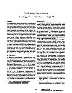
receiver and the apply reader for the other queue. This experiment focuses on the rate at which LCRs are captured at the source database and propagated from the source database to the destination database. Because the applier processes do not directly interact with the latch-free queue, they are irrelevant in this experiment. Hence, we configure the applier processes to discard the LCRs received instead of applying them at the destination database so that the applier processes do not become the bottleneck in this experiment. Fig. 14 shows Oracle Streams' average throughput over 30second intervals before and after the latch-free queue optimization is applied. Without the latch-free queue, the maximum throughput is roughly 5500 LCRs/s, as illustrated by the bottom curve. With the latch-free queue, Oracle Streams is able to achieve throughputs between 21,000 and 25,000 LCRs/s, at which point the capture component becomes the bottleneck. This experiment demonstrates that by taking advantage of Oracle Streams' unique architecture, only one queue producer, we are able to use the special latch-free queue to achieve four to five times higher LCR delivery rate.
90 80 with metadata cache no metadata cache
70 60 50 40 30 20 10 0 0
1
2
3
4
5
6
7
8
9
Apply parallelism Fig. 15 Apply parallelism vs. latch contention
When metadata caching is not used, each applier process must acquire a latch on the table metadata to execute every DML. Because the insert-only workload does not introduce transactional dependencies, transactions can be applied in parallel. As we increase the apply parallelism to allow for a larger number of applier processes to execute DMLs in parallel transactions, the latch contention for accessing the metadata increases, as illustrated in Fig. 15. The increasing latch contention consequently decreases the apply throughput.
When metadata caching is used, concurrent applier processes are able to access the metadata in the cache without acquiring latches. Latch contention is eliminated among applier processes.
contention in accessing the metadata, the overall throughput drops sharply. The metadata cache optimization eliminates this latch contention so that the throughput is higher and steady, as illustrated by the top most curve.
D. End-to-end Throughput Evaluation In this subsection, we demonstrate the end-to-end throughput improvement of Oracle Streams yielded by the optimizations described in this paper. The hardware configuration, the set up of two databases, and the workload are the same as those used in the experiment for the latch-free queue. Similarly, the workload is staged before Oracle Streams is started to avoid the competition of hardware resources between the workload at the source database and Oracle Streams.
E. Replication of Concurrent Workload in LAN and WAN In this subsection, we present both the end-to-end throughput and the replication latency of Oracle Streams replicating concurrent workload in a LAN and a WAN. Although we use similar hardware and workload as in the previous experiment, we run the workload concurrently with Oracle Streams. Note that we reduce the workload generation rate in the WAN experiment to fit the maximum WAN bandwidth. Replication latency is the elapsed time between when a row change was made at a source database and when the same row change was applied at the destination database. Note that the clock granularity of the latency measurement was one second. Furthermore, in the WAN configuration, an actively used corporate network between California and Texas, approximately 1800 miles apart with 50 ms network Round Trip Time (RTT), separates the source and destination databases.
Latch-free Queue + Data Layer API + Metadata Cache Latch-free Queue + Data Layer API
25
20
15
22 10
Latch-free Queue
5
No Optimizations 0 0
100
200
300
400
500
600
Time(s) Fig. 16 End-to-end throughput with various optimizations
Fig. 16 illustrates Oracle Streams’ average end-to-end throughput over 30-second intervals by different combinations of optimizations. Because Oracle Streams captures, propagates, and applies LCRs in a pipelined fashion, the bottleneck component limits the end-to-end throughput of the system. The bottom curve of Fig. 16 shows the throughput of the system before any optimization is applied, which is roughly 5100 LCRs/s. The latch-based queue that we use to stage LCRs among the capture, propagation, and apply components is the limiting factor. After the latch-free queue is used, the throughput is increased up to three times the original rate, as indicated by the second curve from the bottom. After the latch-free queue eliminates the bottleneck in staging LCRs among Streams components, the apply component becomes the bottleneck in applying LCRs at the destination database. Then we observe that the data layer API improves the apply rate by 3000 - 6000 LCRs/s because of the instruction reduction in the data layer API, illustrated by the third curve from the bottom. Both the second and the third curve from the bottom show large fluctuations in throughput due to latch contention on the replica metadata at the destination database. There are multiple applier processes applying transactions in parallel and they need to access the metadata, which is latchprotected for concurrent accesses. When there is latch
Throughput(K. LCRs/s)
Throughput(K. LCRs/s)
30
21 20 19
Throughput in LAN
18 17
Throughput in WAN
16 15 14 13 0
200
400
600
800
1000
1200
Time(s) Fig. 17 LAN vs. WAN throughput
As shown in Fig. 17, Streams’ throughput in the LAN with the concurrent workload at the source database is the same as when workload is staged. Compared to the throughput in the LAN, Streams’ throughput in the WAN is limited by the available bandwidth in the WAN. Furthermore, the throughput in the WAN fluctuates more because the available bandwidth in WAN is volatile. Fig. 18 shows that Streams achieves sub-second latency in the LAN. To minimize network latencies in the WAN configuration, the propagation component streams LCRs over the network with a time-based acknowledgement. The interval for the time-based acknowledgement is 30 seconds in this experiment. In other words, each network RTT is amortized over a 30-second interval. However, the volatility of the available network bandwidth in the WAN leads to the relatively larger fluctuations in Streams replication latency. During our WAN experiment, Streams fully utilizes the
available bandwidth that fluctuates between 4.5MB/s and 5.2MB/s. When the WAN bandwidth drops below the rate at which workload is generated in the source database and captured by Streams, some LCRs must be delayed at the source database. Therefore, the replication latencies for those delayed LCRs increase, as shown in Fig. 18. The latency fluctuations in WAN correspond to the fluctuations of the available bandwidth in the WAN. 4.5
[1]
N. Arora, Oracle Streams for Near Real Time Asynchronous Replication, VLDB Workshop on Design, Implementation and Deployment of Database Replication, VLDB 2005.
[2]
N. Arora, R. Blumofe, C. Plaxton, “Thread Scheduling for Multiprogrammed Multiprocessors”, ACM Symposium on Parallel Algorithms and Architectures, 1998, pp. 119-129.
[3]
J. Aspnes and M. Herlihy. Wait-Free Data Structures in the Asynchronous PRAM Model. In Proceedings of the 2nd Annual Symposium on Parallel Algorithms and Architectures, July 1990, pages 340--349, Crete, Greece.
[4]
E. F. Codd A Relational Model of Data for Large Shared Data Banks, Communications of the ACM, Volume 13, Number 6, June 1970
[5]
D. Daniels, L. Doo, A. Downing, C. Elsbernd, G. Hallmark, S. Jain, B. Jenkins, P. Lim, G. Smith, B. Souder, and J. Stamos, “Oracle’s Symmetric Replication Technology and Implications for Application Design”, Proceedings of the 1994 ACM SIGMOD International Conference on Management of Data, May 24-27, 1994.
[6]
D. Detlefs, P. Martin, M. Moir, and G Steele, “Lock-free Reference Counting,” Distributed Computing, vol. 15, no. 4, pp. 255-271, 2002
[7]
D. Duellmann, “Oracle Streams for the Large Hadron Collider at CERN,” Oracle Open World, San Francisco, November, 2007
[8]
J. Gray, “Notes on Database Operating Systems,” Operating Systems, An Advanced Course, vol. 60, Springer-Verlag, New York, 1978.
[9]
J. Gray, P. Helland, P. E. O'Neil, D. Shasha, “The Dangers of Replication and a Solution”, SIGMOD Conf. 1996: pp.173-182 MSRTR-96-17
4
Latency(s)
3.5
Latency in WAN
3
Latency in LAN
2.5 2 1.5 1 0.5 0 0
200
400
600
800
1000
1200
Time(s) Fig. 18 LAN vs. WAN latencies
VII. CONCLUSION In this paper, we described Oracle Streams, a high performance replication solution for Oracle databases, and its recent performance optimizations. Oracle Streams employs a pipeline of components to replicate database transactions asynchronously. Through a number of optimizations on shared memory, both the delay in transporting LCRs among Streams components and the LCR execution time at database replicas are reduced greatly. In addition, the LCR execution time at a database replica is further shortened when the apply component uses a data layer API, which bypasses SQL. Through simple replication benchmarks, we demonstrated how Oracle Streams can replicate over 20,000 LCRs per second on commodity hardware. Independent analysis from one of our customers demonstrates more than a two-times performance improvement in Oracle Database 11gR1 compared with his prior deployment. ACKNOWLEDGMENT We would like to thank Jim Stamos for numerous discussions that helped shape the arguments presented in this paper. Randy Urbano provided valuable comments that helped improve the layout of this paper. This work would not have been possible without the encouragement of our manager, Alan Downing. REFERENCES
[10] M. Herlihy, J. Wing. “Linearizability: a correctness condition for concurrent objects”, ACM Transactions on Programming Languages and Systems, 12(3):463-492, July 1990 [11] IBM, “WebSphere Information Integrator Q replication”, www.ibm.com/developerworks/db2/library/techarticle/dm-0503aschoff/ [12] L. Lamport, Time, clocks and the ordering of events in a distributed system. Communications of the ACM, 21(7):558−565, July 1978 [13] Y. Lin, B. Kemme, M. Patiño-Martínez, R. Jiménez-Peris, “Middleware based Data Replication providing Snapshot Isolation,” ACM Int. Conf. on Management of Data (SIGMOD), Baltimore, Maryland, June 2005. [14] M. Michael, “High Performance Dynamic Lock-free Hash Tables and List-based Sets,” In Proceedings of the fourteenth annual ACM symposium on Parallel algorithms and architectures, 2002, pp. 73-82. [15] C. Mohan, B. Lindsay, and R. Obermarck, “Transaction Management in the R* Distributed Database Management System,” ACM Trans. Database Systems, vol. 11, no. 4, pp. 378-396, 1986. [16] Oracle Database Advanced Replication 11g Release 1 (11.1), Conflict Resolution Concepts and Architecture. http://www.oracle.com/pls/db111/to_URL?remark=ranked&urlname=ht tp:%2F%2Fdownload.oracle.com%2Fdocs%2Fcd%2FB28359_01%2Fs erver.111%2Fb28326%2Frepconflicts.htm%23REPLN005 [17] Oracle Streams Concepts and Administration 11g Release 1 (11.1). http://www.oracle.com/pls/db111/to_URL?remark=ranked&urlname=ht tp:%2F%2Fdownload.oracle.com%2Fdocs%2Fcd%2FB28359_01%2Fs erver.111%2Fb28321%2Ftitle.htm%23BEGIN [18] F. Pedone, R. Guerraoui, and A. Schiper, "Exploiting atomic broadcast in replicated databases," in Proceedings of EuroPar (EuroPar'98), Sept. 1998. [19] O. Shalev and N. Shavit, “Split-ordered Lists: Lock-free Extensible Hash Tables,” Journal of the ACM (JACM), 53(3):379−405, 2006. [20] A. Tanenbaum, A. Woodhull, Operating Systems: Design and Implementation, Prentice Hall, Englewood Cliffs, NJ, 1987. [21] TPC-C Benchmark Results, http://www.tpc.org