Arun Kuruvila,a Piran R. Kidambi,b Jens Kling,c Jakob B. Wagner,c John Robertson,b ..... 26 M. P. de Jong, L. J. van IJzendoorn and M. J. A. de Voigt, Appl. Phys ...
Volume 2 Number 34 14 September 2014 Pages 6885–7142
Journal of
Materials Chemistry C Materials for optical, magnetic and electronic devices www.rsc.org/MaterialsC
ISSN 2050-7526
COMMUNICATION Jens Meyer et al. Organic light emitting diodes with environmentally and thermally stable doped graphene electrodes
Journal of
Materials Chemistry C COMMUNICATION
Cite this: J. Mater. Chem. C, 2014, 2, 6940 Received 10th June 2014 Accepted 2nd July 2014
Organic light emitting diodes with environmentally and thermally stable doped graphene electrodes† Arun Kuruvila,a Piran R. Kidambi,b Jens Kling,c Jakob B. Wagner,c John Robertson,b Stephan Hofmannb and Jens Meyer*a
DOI: 10.1039/c4tc01224k www.rsc.org/MaterialsC
We present a comparative study of the environmental and thermal stability of graphene charge transfer doping using molybdenum– trioxide (MoO3), vanadium–pentoxide (V2O5) and tungsten–trioxide (WO3). Our results show that all these metal oxides allow a strong and stable p-type doping of graphene, as well as functioning as effective hole-injection layers for highly efficient organic light emitting diodes.
Graphene's potential as a exible transparent conductor and as a replacement for the brittle indium tin oxide (ITO) to enable next-generation exible electronics has recently received considerable research interest. Organic photovoltaic cells (OPV) and organic light emitting diodes (OLED) are two of the many applications that can potentially benet from such an electrode.1–8 However, a number of challenges need to be addressed to realize high opto-electronic performance. Although graphene supports charge carrier mobilities >15 000 cm2 V�1 s�1 and as electrode offers a comparatively low optical absorption over a broad range of wavelengths (�2.3% per monolayer graphene in the visible region), graphene is intrinsically not a highly conductive material due to its low charge carrier concentration.9,10 Hence both high crystalline quality graphene and doping are required to achieve low sheet resistance values. Numerous approaches to graphene doping have been reported in the recent literature. Doping is generally best achieved by charge transfer or electrostatic doping, as substitutional methods tend to degrade the crystalline quality of the graphene.11 Charge transfer chemical doping has been reported for instance by exposure to nitric acid (HNO3), iron chloride (FeCl3), ionic liquids and polymers such as
a
Philips Research, Philipsstrasse 8, 52068 Aachen, Germany. E-mail: jens.meyer@ philips.com
b
Department of Engineering, University of Cambridge, 9 JJ Thomson Avenue, Cambridge CB3 0FA, UK
c Technical University of Denmark, Center for Electron Nanosopy, Fysikvej Building 307, DK–2800 Lyngby, Denmark
† Electronic supplementary 10.1039/c4tc01224k
information
(ESI)
6940 | J. Mater. Chem. C, 2014, 2, 6940–6945
available.
See
DOI:
bis(triuoromethanesulfonyl)amide.6,12,13 Crucial for applications is not only doping efficiency but also environmental and thermal doping stability. For example, OLED specications for automotive applications require materials that are stable up to a temperature of 110 � C. The stability and reliability of dopants are oen not addressed in other reports, where chemicals and graphene doping are unstable to air exposure, humidity, process chemicals and ion mobility. Furthermore, and particularly for organic electronic applications, the band alignments and the charge extraction and injection efficiency across the electrode/organic interfaces are at least as important as the actual sheet resistance of the electrode. A doping strategy in which all these challenges can be simultaneously addressed is the charge-transfer doping of graphene by solution- or physical vapor-deposited metal oxide lms.14–16 Thin MoO3 lms have been demonstrated to not only dope graphene efficiently, but also to form a very effective hole-injection layer, without sacricing the optical and electrical properties of organic devices.16 The doping mechanism is a result of MoO3's unusually large work function (WF) with a value of >6 eV, with electrons strongly attracted to the MoO3 when brought in contact with the graphene.17 Motivated by the promising results obtained with MoO3, here we present a comparative study of the environmental and thermal stability of monolayer graphene charge transfer doping using vanadium–pentoxide (V2O5) and tungsten–trioxide (WO3). Both materials have a very similar electronic structure to MoO3 with WFs in excess of 6 eV.17 We analyze the structure of sub-5 nm thin MoO3, V2O5 and WO3 lms evaporated onto graphene by transmission electron microscopy (TEM) and systematically measure the sheet resistance behavior in various atmospheres and heating up to 110 � C. We show that V2O5 and WO3-based charge-transfer doping is not only efficient, but is also comparatively very stable. Our OLED device characterizations further demonstrate that these metal oxides form an effective hole-injection contact. We monitored in situ the change in sheet resistance of a graphene monolayer during thermal deposition of the metal oxides. The results are summarized in Fig. 1(a–c) in which the
This journal is © The Royal Society of Chemistry 2014
Communication
Journal of Materials Chemistry C
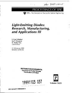
Fig. 1 Sheet resistance values of monolayer graphene measured in air, in vacuum upon heating to 125 � C and subsequent cooling to 25 � C, doping with (a) MoO3, (b) V2O5 and (c) WO3 (left graphs) and N2 exposure for 60 min followed by air exposure for 60 min and heating in vacuum to 110 � C (right graphs). Energy levels of metal oxides taken from ref. 17.
sheet resistance is plotted for the three different metal oxides during deposition (le graphs) and upon our post-treatment routine (right graphs). In all cases the sheet resistance was rst measured in air and then in vacuum aer heating to 125 � C. The heating in vacuum removes the unintentional doping effect due to air exposure. High temperature treatments can almost fully remove the unintentional doping; however, also cracks can be induced in graphene due to different thermal expansion coefcients. Therefore, we used a mild temperature treatment of 125 � C in vacuum which already results in a substantial increase in sheet resistance from �800 to �1300 U sq.�1 as shown in Fig. 1, but without deteriorating the lattice structure. The deposition of a few angstrom MoO3, V2O5 and WO3, respectively, leads to a rapid lowering of the sheet resistance, indicating a strong charge transfer doping. Recently, we investigated the charge transfer process from MoO3 to graphene in detail using photoemission spectroscopy analysis.16 It was found that a 1.9 eV large interface dipole arises, as a result of an electron transfer from graphene to MoO3. This strong p-doping is also self-evident when comparing the WF difference of
This journal is © The Royal Society of Chemistry 2014
graphene (4.4 eV) and MoO3 (6.9 eV). When these materials are brought in contact, Fermi level alignment across the interface can only be obtained by a charge transfer process. Even though MoO3, V2O5 and WO3 have different molecular properties with respect to mass, density and evaporation temperature the electronic structures are very similar.17,18 Therefore, it is likely that these materials show also a comparable charge transfer doping effect, as schematically illustrated in the inset of Fig. 1. Interestingly, the sheet resistance of both V2O5 and WO3 doped graphene drops more rapidly with increasing layer thickness compared to MoO3 which might be attributed to a higher doping efficiency. However, the overall relative change in sheet resistance (�50%) is nearly identical for all three materials. While the overall observed charge transfer doping can be rationalized by the high work functions of the used metal oxides, we emphasize that when looking at differences between the different oxides in the sheet resistance many experimental factors have to be taken into account. These experimental effects include different deposition temperatures for the different oxides, subtle differences in oxidation state
J. Mater. Chem. C, 2014, 2, 6940–6945 | 6941
Journal of Materials Chemistry C
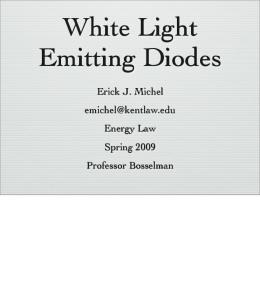
(incl. effects of residual oxygen) and the interface structure to the graphene etc., which is beyond the scope of this study. A comparison with the HNO3 doped graphene layer (Fig. 2(a)) reveals that the charge transfer doping with MoO3, V2O5 and WO3 is as effective as the conventional used nitric acids doping approach. We note here that sheet resistance values of HNO3 doped graphene �300 U sq.�1 have been reported in literature.19 Our higher sheet resistance values refer to the relatively large 4point-probe measurement area of a few square millimeter, that takes into account a meaningful average distribution of grain boundaries and cracks, which are always present in CVD graphene lms post transfer. Fig. 2(b) reveals that by comparing peak instead of average sheet resistance values, we can achieve with our metal oxide doping approach similar low sheet resistance values of �300 U sq.�1 as reported for HNO3 doping. We also like to point out that the sheet resistance of HNO3 doped graphene increases with raising temperature, indicating that HNO3 dopant is not only instable in air, as already reported, but also has a very limited temperature stability. At 120 � C the sheet resistance increases by 90% (Fig. 2(a)). In the following we discuss the doping stability of our metal oxide dopants as shown in the right graphs of Fig. 1. The stability in vacuum was tested by slowly raising the temperature of the samples up to 110 � C, where it was kept constant for 60 min and then cooled down to room temperature. This procedure has no impact on the MoO3 doped graphene sample and led only to minor increase for both the V2O5 and WO3 doped graphene samples. The subsequent exposure to N2 for 60 min demonstrated that this dopant is stable in an inert atmosphere without losing doping efficiency. Only the exposure to air for 60 min reveals a small increase of around 10% in sheet resistance for the MoO3 and WO3 doped samples. An even superior doping stability in air shows the V2O5 dopant, where nearly no changes in sheet resistance are observed. Air exposure of metal oxides can strongly decrease the WF due to a partial reduction at the surface.20–22 We also observed via in situ XPS analysis a strong change of the stoichiometry upon air-exposure (not shown here). It has been shown that long air-exposure of MoO3 can lead to a WF reduction to 5.1 eV.21 A low WF might be the reason for the increase in sheet resistance because of the
Fig. 2 (a) Sheet resistance of HNO3 doped monolayer graphene at different temperatures. (b) Sheet resistance change upon WO3 doping of high quality graphene sheet.
6942 | J. Mater. Chem. C, 2014, 2, 6940–6945
Communication
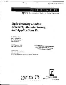
weaker charge transfer doping. However, as only the exposed surface of the metal oxide is chemically reduced the charge transfer doping which takes place at the very interface to graphene is marginally affected. This is also in good agreement to a recent study by Irfan et al. who demonstrated that once the charge transfer between MoO3 and an organic layer is accomplish an additional air exposure has only a small impact on the energy level alignment at the interface.23 Finally, the samples were put back in vacuum followed by a heating to 110 � C. As shown in Fig. 1, this post-treatment leads to a partial (in case of V2O5 and WO3) and nearly complete recovery (in case of MoO3) of the initial sheet resistance before air exposure. Also this observation can be explained by partial recovery of the metal oxides WF. Since the metal oxide growth on graphene can have an inuence on the charge transfer doping we studied the nucleation using TEM analysis. Fig. 3 shows TEM images of graphene covered with 0.5 nm and 3 nm MoO3, V2O5 and WO3, respectively. Thermally deposited metal oxides of 0.5 nm seem to nucleate rst on amorphous residues like PMMA from the transfer and other dirt on the graphene as seen in the TEM images (Figure 3 le column and middle column). Note that TEM samples were not cleaned by annealing in H2. Arrows in the images (le column) mark amorphous residuals and metal oxides. These loose patches show no clear crystalline structure in the beginning, but rearrange slightly under the inuence of the electron beam. Clean graphene areas appear free of metal oxides (see Fig. 3 middle column and insets). No closed network of metal oxides is received for this layer thickness. With further deposition of an additional 2.5 nm i.e. a total of 3 nm metal oxide layer, the Volmer–Weber like nucleation forms a network of an amorphous patchy lm seen for MoO3 and WO3. The lm of V2O5 appears to be more continuous albeit still amorphous at 3 nm. The Fast Fourier Transformations (FFT) of the images (insets Fig. 3 right column) show the amorphous character. Reections found in the FFT of MoO3 and WO3 belong to the underlying graphene structure. We note here that the nucleation of metal oxides on graphene strongly depends on the deposition method. Recently, it has been shown that a continuous 1 nm metal oxide layer (Al2O3) can be grown on graphene via Atomic Layer Deposition.24 With such technique it might be possible to further reduce the metal oxide thickness for efficient charge transfer doping. Finally, we evaluate OLEDs with our metal oxide doped graphene electrodes. We focus here on V2O5 and WO3 since MoO3 doped graphene electrodes have been reported before. The OLEDs characteristics and the device architectures are depicted in Fig. 4(a) and (b). In contrast to most reports in literature we did not use an additional poly(3,4-ethylenedioxythiophene):poly(styrenesulfonate) (PEDOT:PSS) layer to planarize the graphene surface, which makes our approach more relevant for commonly industrial used thermal evaporation processing. Instead, we used a 135 nm thick MoO3 doped 4,40 -bis(N-carbazolyl)-1,10 -biphenyl (CBP) layer as hole-transport and planarization layer. Obviously, it would be also possible to use CBP doped by V2O5 and WO3, respectively, however, MoO3 was chosen because of the lower evaporation temperature
This journal is © The Royal Society of Chemistry 2014
Communication
Journal of Materials Chemistry C
Fig. 3 TEM images of graphene with 0.5 nm (left and middle column) and 3 nm (right column) MoO3, V2O5 and WO3, respectively. Insets in the middle column show the clean graphene structure. Insets in the right column shows the fast Fourier transformation of the images. The deformation of the FFT for MoO3 comes from slight astigmatism of the image.
which is easier to handle in our deposition tool. The device characteristics show that both V2O5 and WO3 not only effectively p-dope graphene, but also form an efficient hole-injection contact, leading to very similar current density–voltage curves and a low-onset voltage of around 2.8 V. These results are comparable to OLEDs with MoO3 doped graphene electrodes.16 The effectiveness of V2O5 and WO3 interlayers is a result of their favourable electronic structure with a WF of >6 eV.17 Thus, by depositing a thin metal oxide layer, charge transfer doping is induced which substantially lowers the sheet resistance of graphene and at the same time forms an efficient hole-injection layer. This simplied process in combination with the high
This journal is © The Royal Society of Chemistry 2014
doping stability is a clear benet of the introduced metal oxides. In addition, a 5 nm metal oxide layer on graphene exhibits a high transmission of >90% in the visible part of the spectrum (see ESI Fig. S1†). Thus highly transparent graphene based electrodes can be realized. Fig. 4(a) shows that the power efficiency of the WO3 doped graphene device is higher as with an ITO electrode. A similar result has been found for MoO3 doped graphene.16 Also other reports in literature have demonstrated that a graphene electrode can be more efficient then ITO. The lower light absorption and the lacking wave guide mode in the extremely thin graphene layer might reduce some loss channels and therefore enhance the efficiency compared to ITO.
J. Mater. Chem. C, 2014, 2, 6940–6945 | 6943
Journal of Materials Chemistry C
Communication
sheet resistance, but also allows for an efficient hole-injection for organic devices.
Methods
Fig. 4 OLED device characteristics with ITO and monolayer graphene
electrode comprising a WO3 (a) and V2O5 (b) interlayer respectively.
For V2O5 doped graphene (Fig. 4(b)) OLED we achieved very high overall power efficiencies of around 80 lm W�1 at 2000 cd m�2 due to optimized process conditions. This values are comparable to the record efficiency which have been lately reported by Li et al.8 (note, we did not use additional outcoupling structure), however, without the use of a PEDOT interlayer, which can deteriorate the device performance because of their water content and acidic nature.25,26 Our results demonstrate that extremely efficient OLEDs can be realized with metal oxide thermally and environmentally stable doped graphene electrodes. V2O5 doped graphene electrodes might be more suitable for applications where a high air-stability is required. This property, however, is not needed for OLEDs and most other organic devices, because the utilized materials are already extremely sensitive to ambient exposure and thus require an encapsulation against water and oxygen. Important, however, is the doping stability in an inert atmosphere. Since V2O5 and WO3 show a comparable high stability in nitrogen, but WO3 is more transparent for high efficiency OLED devices with doped graphene electrode tungsten oxide is the most promising material.
Conclusions In conclusion, we demonstrated highly efficient graphene based OLEDs by introducing charge transfer metal oxide doping. We identied that a 3–5 nm thin layer of MoO3, V2O5 and WO3, respectively, forms a continuous amorphous layer that not only strongly p-dopes graphene and therefore drastically lowers the
6944 | J. Mater. Chem. C, 2014, 2, 6940–6945
A low-pressure chemical vapor deposition (CVD) process was used for the graphene synthesis on commercial, cold-rolled Cu foils (Alfa Aesar Puratronic, 99.999% purity, 25 mm thick) as described in detail elsewhere.27,28 Aer synthesis, a polymethylmethacrylate (PMMA, 495 K diluted to 2% in Anisole) support layer was deposited on graphene on Cu, and 0.1 M aqueous solution of (NH4)2S2O8 was used to etch the Cu foil. This was followed by rinsing in de-ionized water aer which the monolayer graphene/PMMA stack was transferred to the desired substrate (SiO2 (300 nm)/Si or glass substrates i.e. SiO2 1.4 mm thick) and dried. The PMMA support layer was dissolved using hot acetone followed by a rinse in isopropanol and blow dried in nitrogen. Finally, the transferred samples were annealed in 4 mbar H2 at �300 � C for 60 min to remove residual PMMA post transfer. The annealing in H2 was not performed for graphene transferred to TEM grids29 (Ted Pella Holey Silicon Nitride Support Film, 200 nm, 2.5 mm pores, 0.5 � 0.5 mm window, Ø 3 mm). TEM work was conducted in a FEI Titan 80-300 ETEM equipped with a monochromator at the electron gun and a spherical aberration (Cs)-corrector for the objective lens. All images are acquired with the microscope operated at 80 kV acceleration voltage. With the energy spread reduced to below 0.3 eV and the corrector aligned to minimize Cs a resolution better than 0.12 nm is achieved. Samples are heated for 1 h at 350 � C in the microscope to reduce contaminations. The images are background subtracted to reduce inhomogeneous illumination due to the monochromator. All organic and inorganic layers were prepared by thermal evaporation with a deposition rate of 0.1–0.3 nm s�1 in a custom-build deposition system at a base pressure of 10�6 mbar. As substrates we used cleaned ITO pre-coated glass and graphene transferred on glass, respectively. The OLED stack comprises a 5 nm WO3 or V2O5 layer, a 135 nm MoO3 doped 4,40 bis(N-carbazolyl)-1,10 -biphenyl (CBP) hole transport layer, a 5 nm CBP hole transport layer, a 15 nm CBP doped with bis(2-phenylpyridine)(acetylacetonate)iridium(III) [Ir(ppy)2(acac)] (10 wt%) emission layer, a 60 nm 1,3,5-tris-phenyl-2-benzimidazolyl-benzene (TPBi) electron transport layer, a 1 nm 8-hydroxy-quinolinato lithium (Liq) electron injection layer and a 100 nm Al top electrode. In situ 4-point probe measurements were conducted in vacuum at a base pressure of 10�6 mbar.
Acknowledgements We acknowledges the 7th Framework project “GRAFOL” for nancial support (Grant no. 285275). SH acknowledges funding from EPSRC (Grant no. EP/K016636/1 and EP/H047565/1). P.R.K. acknowledges funding from the Cambridge Commonwealth Trust. J.K. and J.B.W. acknowledge the A.P. Møller and Chastine Mc-Kinney Møller Foundation for their contribution toward the establishment of the Center for Electron Nanoscopy in the Technical University of Denmark.
This journal is © The Royal Society of Chemistry 2014
Communication
Notes and references 1 Y. Wang, X. Chen, Y. Zhong, F. Zhu and K. P. Loh, Appl. Phys. Lett., 2009, 95, 063302. 2 T. Sun, Z. L. Wang, Z. J. Shi, G. Z. Ran, W. J. Xu, Z. Y. Wang, Y. Z. Li, L. Dai and G. G. Qin, Appl. Phys. Lett., 2010, 96, 133301. 3 J. Wu, M. Agrawal, H. A. Becerril, Z. Bao, Z. Liu, Y. Chen and P. Peumans, ACS Nano, 2010, 4, 43–48. 4 H. Park, P. R. Brown, V. Bulovic and J. Kong, Nano Lett., 2011, 12, 133. ¨ 5 Y. Wang, S. W. Tong, X. F. Xu, B. Ozyilmaz and K. P. Loh, Adv. Mater., 2011, 23, 1514. 6 T.-H. Han, Y. Lee, M.-R. Choi, S.-H. Woo, S.-H. Bae, B. Hee, B. H. Hong, J.-H. Ahn and J.-H. Lee, Nat. Photonics, 2012, 6, 105. 7 J. Hwang, H. K. Choi, J. Moon, T. Y. Kim, J.-W. Shin, C. W. Joo, J.-H. Han, D. H. Cho, J. W. Huh, S.-Y. Choi, J.-I. Lee and H. Y. Chu, Appl. Phys. Lett., 2012, 100, 13330415. 8 N. Li, S. Oida, G. S. Tulevski, S.-J. Han, J. B. Hannon, D. K. Sadana and T.-C. Chen, Nat. Commun., 2013, 4, 2294. 9 R. R. Nair, P. Blake, A. N. Grigorenko, K. S. Novoselov, T. J. Booth, T. Stauber, M. R. Peres and A. K. Geim, Science, 2008, 320, 1308. 10 A. Pirkle, J. Chan, A. Venugopal, D. Hinojos, C. W. Magnuson, S. McDonnell, L. Colombo, E. M. Vogel, R. S. Ruoff and R. M. Wallace, Appl. Phys. Lett., 2011, 99, 122108. 11 H. Terrones, R. Lv, M. Terrones and M. S. Dresselhaus, Rep. Prog. Phys., 2012, 75, 062501. 12 D. Zhan, L. Sun, Z. H. Ni, L. Liu, X. F. Fan, Y. Wang, T. Yu, Y. M. Lam, W. Huang and Z. X. Shen, Adv. Funct. Mater., 2010, 20, 2504. 13 D. Kim, D. Lee, Y. Lee and D. Y. Jeon, Adv. Funct. Mater., 2013, 23, 5049. 14 S. L. Hellstrom, M. Vosgueritchian, R. M. Stoltenberg, I. Irfan, M. Hammock, Y. B. Wang, X. Guo, Y. Gao and Z. Bao, Nano Lett., 2012, 12, 3574.
This journal is © The Royal Society of Chemistry 2014
Journal of Materials Chemistry C
15 Q.-H. Wu, Y. Zhao, G. Hong, J.-G. Ren, C. Wang, W. Zhang and S.-T. Lee, Carbon, 2013, 65, 46. 16 J. Meyer, P. R. Kidambi, B. C. Bayer, C. Weijtens, A. Kuhn, A. Centeno, A. Pesquera, A. Zurutuza, J. Robertson and S. Hofmann, Sci. Rep., 2014, 4, 5380. 17 J. Meyer, S. Hamwi, M. Kroger, W. Kowalsky, T. Riedl and A. Kahn, Adv. Mater., 2012, 24, 5408. 18 M. T. Greiner, M. G. Helander, W.-M. Tang, Z.-B. Wang, J. Qiu and Z.-H. Lu, Nat. Mater., 2012, 11, 76. 19 S. Bae, H. Kim, Y. Lee, Y. Xu, J.-S. Park, Y. Zheng, J. Balakrishnan, T. Lei, H. R. Kim, Y. I. Song, Y.-J. Kim, ¨ K. S. Kim, B. Ozyilmaz, J.-H. Ahn, B. H. Hong and S. Iijima, Nat. Nano, 2010, 5, 574. 20 J. Meyer, A. Shu, M. Kr¨ oger and A. Kahn, Appl. Phys. Lett., 2010, 96, 133308. 21 I. Irfan, H. J. Ding, Y. L. Gao, D. Y. Kim, J. Subbiah and F. So, Appl. Phys. Lett., 2010, 96, 073304. 22 J. Meyer, K. Zilberberg, T. Riedl and A. Kahn, J. Appl. Phys., 2011, 110, 033710. 23 I. Irfan, C. Wang, A. J. Turinske and Y. Gao, Proc. SPIE, 2012, 8476, 847616. 24 B. Dlubak, P. R. Kidambi, R. S. Weatherup, S. Hofmann and J. Robertson, Appl. Phys. Lett., 2012, 100, 173113. 25 F. So and D. Kondakov, Adv. Mater., 2010, 22, 3762. 26 M. P. de Jong, L. J. van IJzendoorn and M. J. A. de Voigt, Appl. Phys. Lett., 2000, 77, 2255. 27 P. R. Kidambi, B. C. Bayer, R. Blume, Z.-J. Wang, C. Baehtz, R. S. Weatherup, M.-G. Willinger, R. Schloegl and S. Hofmann, Nano Lett., 2013, 13, 4769. 28 P. R. Kidambi, C. Ducati, B. Dlubak, D. Gardiner, R. S. Weatherup, M.-B. Martin, P. Seneor, H. Coles and S. H. Hofmann, J. Phys. Chem. C, 2012, 116, 22492–22501. 29 P. R. Kidambi, B. C. Bayer, R. S. Weatherup, R. Ochs, C. Ducati, D. V. Szab´ o and S. Hofmann, Phys. Status Solidi RRL, 2011, 5(9), 341.
J. Mater. Chem. C, 2014, 2, 6940–6945 | 6945