TECHNO BYTES
Completing the 3-dimensional picture Christopher Lanea and William Harrell, Jrb Atlanta, Ga and Alexander City, Ala Orthodontics has a commitment to precision and accuracy similar in concept to physical engineering. Both work in a 3-dimensional (3D) world—the engineer designing and modeling physical products, and the orthodontist diagnosing and treating patients. To achieve the best possible results, both fields have readily adopted and successfully implemented highly advanced mathematical techniques and sophisticated protocols. Today, a notable difference between the 2 fields relates to the data input and analysis/modeling tools that are now available. Technology advances in the past 5 years have started to erode these barriers to safely make human 3D data input as precise and easy to obtain as physical 3D object input. Many are familiar with the advances in 3D computed tomography, specifically cone-beam technology; this article focuses on a sister imaging technology called 3D surface imaging. These 3D systems enable extraoral imaging protocols to be equally precise in providing highly accurate 3D facial surface images for diagnosis, analysis, treatment monitoring, simulation, and outcome evaluation. (Am J Orthod Dentofacial Orthop 2008;133:612-20)
O
rthodontics is distinguished by a commitment to precision and accuracy similar in concept to physical engineering. Both fields work in a 3-dimensional (3D) world—the engineer designing and modeling physical products, and the orthodontist diagnosing and treating patients. To achieve the best possible results, both fields have readily adopted and successfully implemented highly advanced mathematical techniques and sophisticated protocols. Today, a notable difference between the 2 fields relates to the data input and analysis/modeling tools that have historically been readily available to each field. Engineers generally base their work on highly precise 3D data input when 3D surface scanners for capturing inanimate objects became available in the 1980s. Many computer-aided-design/computer-aidedmanufacturing (CAD/CAM) software applications were reengineered to make the transition from 2-dimensional (2D) to 3D. As manufacturing firms improved time efficiencies and saved money by streamlining, a paradigm shift became mandatory for the industry. Orthodontists have traditionally based their diagnosis and treatment planning on various 2D radiographs and traditional photographs because conventional 3D input devices for capturing living, breathing human subjects have been prohibitively expensive and complex to use, and often subjected the patient to potentially harmful emissions. a
Chairman and chief executive officer, Atlanta, Ga. Private practice, Alexander City, Ala. Dr. Harrel Jr is not employed by or paid by 3dMD. Reprint requests to: William Harrell, Jr, 125 Alison Dr, Suite 1-A Medical Arts Building, Alexander City, AL 35010; e-mail,
[email protected]. Submitted, August 2006; revised and accepted, March 2007. 0889-5406/$34.00 Copyright © 2008 by the American Association of Orthodontists. doi:10.1016/j.ajodo.2007.03.023
b
612
Technology advances in the past 5 years have eroded these barriers to safely make 3D human data input as precise and easy to obtain as 3D physical object input (Fig 1). Moreover, to further streamline practice workflow, some practice management and imaging management software applications are being reengineered to efficiently handle and analyze these highly precise 3D data formats. Many are familiar with the advances in 3D computed tomography (CT), specifically cone-beam CT (CBCT) technology; this article focuses on a sister imaging technology called 3D surface imaging. These 3D systems enable the extraoral imaging protocol to be equally precise in providing highly accurate 3D surface images for diagnosis, analysis, treatment monitoring, and outcome evaluation. Although mandibular advancement has a noticeable affect on the appearance of the face, some conditions and orthodontic treatment protocols affect the soft tissues. For example, when a palatal expansion appliance is used, there are often obvious soft-tissue changes to parts of the face (eg, the base of the nose) during treatment. These changes are apparent not only to the orthodontist, but also to the patient. With the readily available softtissue capture tools, orthodontists can now accurately document the patient electronically in 3D to evaluate, monitor, and quantify these outcomes (Fig 2). Today, 3D surface data can be registered with 3D CT and CBCT data to provide a thorough view of the patient from the outside in. 3D surface imaging provides added value for diagnosis
Although the patient “wow” factor is clear from a marketing perspective for the orthodontic practice,
American Journal of Orthodontics and Dentofacial Orthopedics Volume 133, Number 4
Lane and Harrell 613
calibration of the two images provokes questions concerning the validity of quantitative information derived from the imaging systems. Even with the best techniques available for coordinating photographs with corresponding cephalograms, the degree of accuracy may be variable, which is a factor that could affect the validity of the video imaging process.
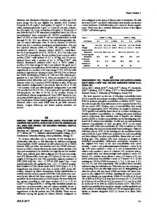
Fig 1. High-precision 3D surface image generated by 3dMD.
understanding that 3D surface imaging can improve diagnosis and enhance treatment planning is the real push behind the 3D surface imaging (Fig 3). Traditional lateral and frontal photographs have well-known limitations as they attempt to accurately record 3D geometry on a 2D plane.1 To work within these recognized limitations, the orthodontic community has established strict photography protocols to extract the best information possible within the constraints of the medium. Limitations of traditional photography
From its invention, photography has been used to document the human condition. It was readily adopted by the medical community to enhance the patient record. Several variables can cause disparity when comparing 2 apparently similar photographs: distance between camera and subject, camera angle, head position (roll-pitch-yaw orientations), and photography protocol inconsistencies (Fig 4). These problems are further compounded when combining a patient’s lateral photograph with a lateral cephalometric image for analysis. Achieving a repeatable and reliable registration between the 2 images is unlikely, considering all of the variables involved. Sarver2 described the limitations of integrating a 2D lateral cephalogram and a 2D lateral photograph for analysis purposes: Usually, facial images and cephalograms are not taken simultaneously, which may result in significant differences in head position and image-magnification discrepancies. Alterations of either the cephalometric profile or photographic image is often required in order to correlate the two images. This “best fit”
To address these limitations created by head position and magnification, 3D CBCT and 3D surface data sets give the orthodontist digital patient information that is 1:1. In an ideal world, both images would be taken simultaneously to minimize registration errors. Integration of the 2 technologies has several drawbacks because the purpose of the 3D photograph is more than just scraping color texture on top of the CBCT. For example, the patient’s head must be secured in an unnatural orientation to minimize movement during the CBCT scan. The stand-alone 3D surface-imaging system allows the orthodontist to capture multiple surface images during treatment to monitor facial changes and, importantly, the patient’s natural head position to use as the face’s natural orientation for treatment planning (Arnett and Bergman3 and Moorrees4). Because each 3D data set is accurate on its own merit, it is possible to register images that have not been taken at the same time by establishing a facial expression protocol5 (Fig 5). Enlow and Hans6 reported that “the breadth of the nasal bridge in the region just below the frontonasal sutures does not markedly increase from early childhood to adulthood.” Therefore, this might prove to be a good registration area for growth assessment and treatment effects. Advantages of moving to 3D surface imaging
Depending on the 3D surface-imaging system used, the process of imaging a patient in 3D can be simpler and take less time than traditional photography. The patient sits in front of the 3D camera, the operator clicks a button, and, from this single 3D data set, any 2D photographic view can be generated—left and right laterals, frontal, left and right obliques, and so on. There is no need to continually reposition the patient in front of the camera; the camera operator simply makes the patient comfortable and relaxed and then acquires each facial expression as required by the practice protocol, whether it is repose, narrow smile, wide smile, or all of them. Because some 3D surfaceimaging systems are noninvasive, images can be taken as frequently as needed. Additionally, the imaging speeds from some machine-vision camera-based stereophotogrammetry systems are so fast that even erratic movement by the youngest child or the most restless patient is not an issue. Once the 3D surface image has
614 Lane and Harrell
American Journal of Orthodontics and Dentofacial Orthopedics April 2008
Fig 2. Quantifying outcomes of palatal expansion treatment plan.
Fig 3. 3dMD analysis software enables users to measure angles and distances between landmarks.
been acquired, it becomes the foundation of the visible patient record ready for analysis at any time. Today, several surface-imaging technologies are available to take extraoral 3D images of a patient’s face. Based on commercially available systems, in this article, we will attempt to explain how the raw 3D surface data is generated, how the underlying imaging technologies work from an accuracy standpoint, the importance of acquisition speed, how the technologies are engineered to become a product to handle patient flow, and how to evaluate the company or organization behind the imaging system. How the 3D surface image is generated
To truly take advantage of 3D, the geometry, or shape data, must be an accurate representation of the patient’s anatomy (Fig 6). As in engineering, good data
input combined with a solid treatment protocol equals good data output. Typically, depending on the system, there are 2 steps for creating the 3D surface image. First, the geometry is generated, and then the color texture information is applied to the geometry. To mathematically express 3D surface information, the subject’s dimensional face must be converted into a series of coordinates with an x, y, and z definition. These coordinates numerically represent the visible geometry of the patient’s face. Some close-range surface-imaging devices automatically generate a point cloud that is relative to a fixed point, or (0, 0, 0) coordinate. Other close-range surface-imaging devices have adapted the methodology of long-range scanning devices (such as 3D topographic measurement from satellite images) to generate a range map, which represents the relationship between points on the target surface and the location of 1 image sensor. Regardless of method, to adequately cover larger surface areas, such as the face (ear to ear) or the full head, acquisition from several viewpoints is required. To evaluate a system, it is good to understand how the mathematical coordinate system for the entire surface image is generated because it is the foundation for accuracy. In principle, there are generally 2 ways to generate a surface image that is derived from multiple viewpoints. The first is to generate a separate 3D data set (containing its own coordinate system) from each viewpoint, whether a range map or a point cloud, and then stitch them together to produce a new 3D coordinate system. Generating separate data sets for each viewpoint and then stitching them together has historically worked well for data input of inanimate objects since subject motion is not a factor. Unfortunately, this stitching approach does not work well when the sub-
American Journal of Orthodontics and Dentofacial Orthopedics Volume 133, Number 4
Lane and Harrell 615
Fig 5. 3dMD analysis software enables users to automatically register data with CBCT data.
Fig 4. Standard patient photographs.
jects are animate, because stitching separate 3D images together to generate a single 3D model of the patient can compromise accuracy.7 There are sometimes clues in the 3D data set that this might be the case, such as a visible seam between the 2 original data sets that were stitched together. If there is no seam with this methodology and the capture speed is longer than 1/250 second (equivalent to 4 ms), there might be “smoothing processes” working behind the scene. To eliminate the extra steps—stitching—that increase the probability of creating data errors, the
preferable way to generate a 3D surface image derived from multiple viewpoints is to generate a continuous coordinate system by selecting the best quality data for any x, y, and z coordinate from each viewpoint. This is typically accomplished through a 4-ms or less capture speed and sophisticated algorithms for evaluating and analyzing sensor images. Currently, no commercially available 3D surface scanner has been validated to capture hair volume accurately on a strand-by-strand basis, but some software routines have been implemented to approximate the 3D data to generate hair structure geometry. Because these approximation routines might not stop at the hairline, it is good to understand how the routines could affect the overall accuracy of the data set. Although there can be a marginal esthetic value for patients when they see their 3D surface image, when it comes to generating geometry for a patient’s hair, there are challenges. These challenges include the reflective properties of each hair strand for optics-based systems and the sheer complexities of generating a geometry that truly represents the hair to the level of detail required to represent many hair strands. Groomed facial hair is typically not a problem. From a treatment planning standpoint, hair tends to complicate facial diagnosis, analysis, and outcome evaluation. As a general rule, most orthodontists and surgeons who currently use a 3D surface-imaging device have the patients pull their hair off the face and forehead, and behind the ears. The reason for this is that they want to image as much of the face as possible
616 Lane and Harrell
American Journal of Orthodontics and Dentofacial Orthopedics April 2008
Fig 6. 3dMD raw data mesh (with and without texture) shows 1 continuous x, y, and z coordinate system generated from 2 separate viewpoints—left and right sides of face.
including the ears because their diagnosis and treatment plans pertain to fully understanding and documenting the soft tissues of the face. Because a patient’s hair changes from 1 visit to the next, there is limited value in documenting the geometry. The application of color texture information is the second step after the geometry is generated. Depending on the imaging system during this process, the color information or the texture map is mathematically applied to the shape data. Whereas many CAD/CAM programs color code different geometry inputs, to date, multimedia production has had the most experience in using 3D input with associated texture maps. Because the color texture map can hide a multitude of sins in the underlying geometry, the first request by most digital artists when reviewing a 3D data sample is to turn off the color texture so that they can fully inspect the foundation geometry. Some 3D photography systems are used as a portable imaging solution moving from 1 location to another to gather vast amounts of data from different patient populations. Since recording the geometry of the patient’s face is the primary goal for these users, many sacrifice external flash lighting for ease of setup and unencumbered portability. This compromise can be determined individually because poorly lit color and texture or visible shadows on the texture have no impact on the accuracy of the geometry. It is purely esthetic. Importance of speed in 3D surface imaging
When imaging the surface of a subject, the speed of capture is critical. In contrast to internal modalities
when layers of geometry are combined with the surface geometry, the 3D surface image has a single layer of x, y, and z coordinates to plot the geometry and the color map. Because patients are living, breathing, and certain to move, the speed of acquisition must be fast enough to freeze motion. Since motion is known to affect traditional close-up photography, many camera manufacturers provide guidelines about appropriate shutter speeds for obtaining a sharp, in-focus result. For a sharp picture, the fastest practical shutter speed is the safest to use, because . . . [there is] less time for subject movement . . . to blur the photograph. Faster shutter speeds will freeze all movement. A safe working speed for handheld shots with a normal lens is 1/125 second—fast enough to stop camera shake and freeze all but rapid motion. Close-ups need faster speeds—1/250 or 1/500 seconds.8
According to international photographer Burden,9 “The difference in real time between 1/250 of a second and 1/30 of a second may not seem long, but when measured in photographic time, it’s huge. It means the difference between freezing the motion and getting a blur.” In a camera- (or optics-) based 3D surface-imaging system, many cameras are synchronized to image the subject. It is not enough for each camera to fire on its own within the 1/250 time window (equivalent to 4 ms); all cameras in the 3D system must fire within the 1/250 time window to ensure capturing the subject at the same time. With poorly synchronized cameras, this window could easily to extend to 30 or 50 ms (or 1/33
American Journal of Orthodontics and Dentofacial Orthopedics Volume 133, Number 4
to 1/20 of a second) or worse. With some slower optics-based systems, especially those designed originally for multimedia or animation purposes, the model reconstruction software is usually designed to compensate for the time lag by filling in gaps and holes in the reconstructed data, as well as regularizing the geometry mesh when the raw geometry data is noisy or missing. These compensation reconstruction routines can introduce errors when validating the accuracy of the geometry. 3D surface-imaging technologies
Even though each of these 3 techniques (laser, structured light, and stereo photogrammetry) can vary from one manufacturer to another, here are basic descriptions. In laser-based imaging technologies, the laser scanner was one of the first 3D surface-imaging technologies available. Depending on the application, it normally uses straightforward geometric triangulation to determine the surface coordinates of the target object. As the name implies, the technique uses scanning a laser beam (spot or stripe) across the surface area of the target object. The object scatters the light, which is then collected at a known triangulation distance from the laser. By using trigonometry, the x, y, and z coordinates of a surface point are calculated. Although the 3D model generated might be accurate on a band-by-band basis, a single human face comprises thousands of bands from top to bottom, and each band is taken sequentially. To achieve any meaningful accuracy in capturing the face, scan times can take up to 20 seconds. Whereas this amount of time works adequately for industrial applications such as reverse engineering, quality inspection, and prototyping, laser technologies are difficult to use on living, breathing people, especially children.10 Optical-based imaging technologies include structured light and stereo photogrammetry. The structured light technique projects organized patterns of white light, such as grids, dots, or stripes, onto the subject, while simultaneously photographing the subject with a camera that is calibrated with the specifics of the projected light pattern. Recording the distortion of the light pattern, the photograph is processed by the associated software to generate the shape data. Color texture information is inherently registered with the point cloud’s range information. Although this method is adequate for smaller capture areas, the user is challenged to generate an accurate 3D model of a human subject’s face from ear to ear because it requires a 2-viewpoint capture. Due to the nature of the pattern
Lane and Harrell 617
projected, these images must be taken in sequence to avoid pattern interference: ie, a grid pattern from 1 viewpoint overlapping a grid pattern from another angle. Sequential image capture extends the acquisition duration, which, for human subjects, can be detrimental to data accuracy. The stereo photogrammetry technique is a sophisticated software approach based on the fundamental principle of taking 2 pictures of the same object, at a distance similar to the distance between a person’s eyes, to create a stereo pair and to record depth. Stereo photogrammetry uses sophisticated stereo triangulation algorithms to identify and match unique external surface features between the 2 photographs and generate a composite 3D model. If the system extracts a point cloud, the underlying software must know the exact position of each camera sensor relative to the others; this is calculated against a known target during the initial calibration exercise. The pattern on the surface provides the stereo algorithms with the base information required to build accurate geometry. Once the 3D geometry model has been produced, the software maps the color texture information onto the model. There are two basic lighting approaches for stereo photogrammetry—passive and active. The true passive stereo approach bases its triangulation technique on the natural patterns or landmarks on the actual surface of the target object. To image the face, the passive approach relies on its ability to resolve details on the surface—skin pores, freckles, scars, and so on. Because this approach highly depends on the integrity of the pixels, it typically synchronizes high resolution single-lens reflex (SLR) cameras to ensure that there is enough surface detail to triangulate the geometry.11 As a result, the system operator must implement procedures to carefully control the lighting conditions to minimize ambient spectral (stray light) reflections and address the workflow issues that result in having to frame and focus several cameras in a synchronized fashion to image a patient. In contrast, an active stereo approach bases its triangulation technique on the natural patterns or landmarks on the actual surface of the target object and proactively combines this natural pattern with a projected unstructured light pattern to give the stereo algorithms as much information as possible to triangulate the geometry (Fig 7). Typically, active stereo is much more resilient to variances in lighting conditions, since the system takes full control of subject lighting during image acquisition; this also eliminates ambient spectral interference. An additional benefit of active stereo relates to acquiring color information. Mature
618 Lane and Harrell
American Journal of Orthodontics and Dentofacial Orthopedics April 2008
Fig 7. 3dMDface system consists of 6 medical-grade, machine-vision cameras that are synchronized to image 1 subject in 1.5 ms, enabling geometry to be processed as 1 continuous point cloud; single raw data set with 1 coordinate system (no stitching) provides ear-to-ear coverage.
active stereo algorithms can easily capture darker skins and black clothing, since the variations in dark and light patterns provide adequate surface information to triangulate the x, y, and z coordinates. with the active stereo technique, a well-implemented system can image the darkest of skin tones. Accuracy has 2 principal components: absolute accuracy with respect to the physical reference of an object, and repeatable accuracy (consistency between discrete scans). When reviewing a 3D imaging system, it is a good idea to ask for an accuracy validation study conducted by an independent third-party organization. Since it is easier to use an inanimate object as the subject when stitching data together because there is no movement, make sure one validation test uses live, unsedated subjects.12 For the 3D surface image to have any validity, the geometry generated must reflect the true contours of the actual anatomical surface down to a small fraction of a millimeter. Product engineering of the 3D surface-imaging device
Another aspect of selecting a 3D surface-imaging device focuses on the practical use of the equipment and how it will work every day in a busy practice. With limited resources such as office space, manpower, and cost, it would be helpful to evaluate the system’s footprint, user friendliness, and durability. In most practices, space is limited, so the smaller the area (footprint) required to operate the system, the better. From a patient workflow perspective and a usage
standpoint, there are a few considerations to evaluate when locating the system in the practice. First, it is important to understand the entire space requirement, not just the system’s footprint, but the space required for the patient, the operator, and any additional features, because some systems require a backdrop behind the patient. Since these systems typically rely on calibration, placing them in high traffic areas such as a hallway greatly increases the chance of the system getting bumped and therefore getting out of calibration. Many practices have wall-mounted systems that maintain consistency of patient positioning across visits. A consistent protocol is especially important if the 3D surface image is to be accurately registered to a CB or traditional CT image. It is important to understand the entire process from calibrating the system and capturing the data to processing the 3D image and the final display in a practice management environment. To fully understand what will be involved with the day-to-day operation of the equipment, it is recommended seeing the system in use in a busy practice and talking to its users. All 3D systems require calibration of the sensor positions before use, so that the user can achieve consistent results on each click. Some aspects to assess are (1) calibration routine (is it simple and can it be done by the staff?); (2) actual data capture (must the patient stay still for a certain amount of time and how many images are taken to obtain ear-to-ear coverage?); (3) imageprocessing procedure (does the 3D data process automatically or how long does it take before the 3D image
Lane and Harrell 619
American Journal of Orthodontics and Dentofacial Orthopedics Volume 133, Number 4
Understand the organization behind the 3D imaging system
Fig 8. Example of machine vision camera technology.
is ready for display?); and (4) integration with a practice management system. If an orthodontist wants to image all or most patients during treatment, not just a few for an occasional research project, the 3D surface-imaging system must be reliable and robust enough to withstand daily use. To get a feeling for the durability of a system, it is good to understand its weaknesses and its individual components. When evaluating optics-based systems, the type of cameras in the system could have an impact on reliability over time. For example, 3dMD purposefully incorporated medical grade, machine-vision cameras into its system (Fig 8). These sensors are generally of a much higher quality and consistency than those in consumer and professional SLR cameras. Machine-vision cameras are designed for engineering and industrial applications running continuously for several years and have a regimented ability to be configured to tightly synchronize the firing times. In contrast, off-the-shelf SLR camera capture speeds are constrained by the manufacturer’s preset synchronization speed ratings with the flash. If the SLR cameras in the 3D system are synchronized with external flash units, the camera shutter speeds cannot capture the image any faster than the rated sync speed with flash. According to photographer Rockwell,13 “Sync speed is important to pros [because] fast sync helps stop motion. 1/250 is not what we want and 1/125 is out of the question. We need to shoot at 1/500 or faster to stop action.”
When patients choose an orthodontist, it usually does not come down to who simply has wires and brackets. Patients typically use a particular orthodontists by referreal from their dentist, word-of-mouth satisfaction, seeing pleasing results on their friends, and the caring attitude of the doctor and staff during the treatment phase. When evaluating 3D surface-imaging system suppliers, an orthodontist should take a similar approach. Take a close look at the customer base such as (1) the number of 3D systems sold to date and their location geographically in relation to the practice; (2) of these customers, the percentage working with the system in a busy practice or hospital; (3) whether the organization is committed to supporting open access to software from other software suppliers; and (4) the number of customers who are actually orthodontists and the organization’s track record to date. This last question is extremely important because a customer base dictates future functionality and technology advancements. If the customer base consists primarily of video-game developers or engineers, how will this affect the orthodontist in product development priorities? Make sure that the organization can demonstrate its commitment to the orthodontic community. Commitment can cover all imaging system points discussed in this article and the organization’s commitment to integration with practice management systems and developing 3D software applications designed to specifically assist orthodontists with treatment planning, monitoring, and outcome evaluation. CONCLUSIONS
With 3D input devices and application software now fine tuned for streamlining human form data, orthodontists can solve problems using factual digitized 3D models just like their counterparts, engineers. With electronic records storing anatomically precise shape data of each patient, orthodontists and staff members can pull these records at any time to analyze or reanalyze the patient and continually monitor the condition during treatment. With the ability to continually monitor and quantify change, experienced practitioners can be more adventurous in modifying treatment plans with the increasing range of new appliances and treatment techniques without risking a less desirable outcome on their patients. A good-quality 3D surfaceimaging system complements 3D CBCT by adding accurate, realistic surface information to the anatomical
620 Lane and Harrell
model. Because it is noninvasive, patients can be imaged at every visit during treatment. In future articles, the application of 3D surface imaging for actual patients will be described to demonstrate how it can be used successfully to change the approach to treatment planning and ultimately permit the orthodontist to simulate the possible outcomes of the chosen treatment plan. REFERENCES 1. Honrado C, Lee S, Bloomquist D, Larrabee W. Quantitative assessment of nasal changes after maxillomandibular surgery using 3-dimensional digital imaging system. Arch Facial Plast Surg 2006;8:26-35. 2. Sarver DM. Esthetic orthodontics and orthognathic surgery. St Louis: Mosby; 1998. 3. Arnett GW, Bergman RT. Facial keys to orthodontic diagnosis and treatment planning. Part I. Am J Orthod Dentofacial Orthop 1993;103:299-312. 4. Moorrees CFA. Natural head position—a revival. Am J Orthod Dentofacial Orthop 1994;105:512-3. 5. Idiculla AJ, Harrell WE, Secchi AG, Ayala J, Katz SH. 3-dimensional morphometric facial analysis to determine the effects of altering the occlusal vertical dimension [thesis]. Philadelphia: University of Pennsylvania; 2006. 6. Enlow DH, Hans MS. Essentials of facial growth. Philadelphia: W. B. Saunders; 1996. 7. Singh GD, Levy-Bercowski D, Santiago PE. Three-dimensional nasal changes following nasoalveolar molding in patients with unilateral cleft lip and palate: geometric morphometrics. Cleft Palate Craniofac J 2005;42:403-9. 8. Take better pictures. New York: Time-Life Books (in association with Kodak); 1983. 9. Burden R. Shutter Speed Importance. Available at: www. takegreatpictures.com/HOME/Columns/Photo_Tips_-_Techniques/ Details/shutter_speed_importance.fci). Accessed January 13, 2008.
American Journal of Orthodontics and Dentofacial Orthopedics April 2008
10. Krimmel M, Kluba S, Bacher M, Dietz K, Reinert S. Digital surface photogrammetry for anthropometric analysis of the cleft infant face. Cleft Palate Craniofac J 2006;43:350-5. 11. McFarlane NJB, Wu J, Tillett RD, Schofield CP, Siebert JP, Ju X. Shape measurements of live pigs using 3D image capture. J Anim Sci. In press. 12. Aldridge K, Boyadjiev SA, Capone GT, DeLeon VB, Richtsmeier JT. Precision and error of three-dimensional phenotypic measures acquired from 3dMD photogrammetric images. Am J Med Genet A 2005;138:247-53. 13. Rockwell K. The Importance of Flash Sync Speed. Available at: www.kenrockwell.com/tech/syncspeed.htm. Accessed on January 13, 2008.
APPENDIX
With more than 200 customers worldwide (as of December 31, 2007) for 3D systems and more than a 10-year proven track record of continuous 3D product development, 3dMD has engineered active stereo photogrammetric-based 3D surface-imaging systems that are highly precise, easy to use, and extremely reliable for busy environments. 3dMD’s goal is to focus on achieving the highest accuracy while keeping workflow simple. During the past 6 years, many practices and research institutions have been using 3dMD systems. The accuracy and reliability of the 3D data captured by these systems has ensured a significant legacy of data and experience to support future research of patient facial anatomy before, during, and after treatment. As empirical understanding of facial structure progresses, 3dMD will work with the orthodontic community to return to that base of detailed data to test and refine these hypotheses. For more information, visit www.3dMD.com.