ISSN 0020-4412, Instruments and Experimental Techniques, 2017, Vol. 60, No. 1, pp. 46–49. © Pleiades Publishing, Ltd., 2017. Original Russian Text © S.R. Korzhenevskiy, A.A. Komarskiy, A.S. Chepusov, V.A. Bessonova, V.N. Titov, 2017, published in Pribory i Tekhnika Eksperimenta, 2017, No. 1, pp. 30–32.
ELECTRONICS AND RADIO ENGINEERING
Output Voltage Adjustment of a Pulsed High-Voltage Nanosecond Generator with Inductive Energy Storage and a Solid-State Switching System S. R. Korzhenevskiy*, A. A. Komarskiy, A. S. Chepusov, V. A. Bessonova, and V. N. Titov Institute of Electrophysics, Ural Branch, Russian Academy of Sciences, Yekaterinburg, 620016 Russia *e-mail:
[email protected] Received February 1, 2016
Abstract—The possibility of adjusting the output voltage of a high-voltage nanosecond pulse generator with inductive energy storage and a solid-state switching system was investigated. All components of the adjustment system are installed in the low-voltage input circuit of the generator, whose voltage was less than 1000 V. The smooth adjustment of the output voltage in the range of 70–115 kV was achieved. The experimental setup and the obtained results are described. DOI: 10.1134/S0020441217010213
1. INTRODUCTION One of the most important fields of application of high-voltage pulse engineering is the generation of powerful radiation fluxes, in particular, X ray. There are two types of X ray generators: DC units with thermal emission tubes and pulse units with explosiveemission tubes. In contrast with DC units, the cathode filament system is missing in the pulsed radiators and the generation of X ray is carried out as the series of nanosecond duration pulses. A short pulse duration makes it possible to reduce the requirements on insulation gaps sharply; as a result, the pulsed devices are many times lighter than the DC devices of an appropriate voltage. The absence of a thermoionic-emission cathode makes it possible to generate pulses with current amplitudes in hundreds of amperes, reach the megawatt peak power level, and 220 V 50 Hz
L1
D1D4 +
reach durations of exposure of less than 100 ns. A significant disadvantage of the pulsed devices is the impossibility to adjust the output voltage due to the feature of the traditionally used power-supply circuit of the explosive-emission tube. The explosive-emission cathode operates reliably only with the rapid growth of voltage amplitude in the accelerating gap of tube. The typical speeds are tens of kilovolts per seconds. Such speeds are provided by applying capacitive energy storage and a high-pressure gas-filled discharger-peaker [1, 2]. The design of developed sealed-off dischargerspeakers does not make it possible to change the turnon voltage quickly; thus, a series of dischargers with different operating voltage was developed. This situation leads to the necessary to create separate specialized high-voltage generators for various tasks.
D5
610 V
С2 Тr1
D6 С1
Тr2
115 kV
VS1 SOS
L2 С3 17.5 kV
Load
С4 54 kV
Fig. 1. The circuit diagram of a generator with two links of magnetic compression. D1–D6 are KD203G, VS1 is a TСhI100-7, SOS (semiconductor opening switch) is a semiconductor current interrupter; C1 is a REC-350-470 μF capacitor (6 pcs), C2 is an Epcos B32654A6684J1000-630-0.68 μF capacitor (6 pcs), C3 is a KVI-3-6800 pF-12 kV capacitor (2 pcs), C4 is a KVI-3-1000 pF-16 kV capacitor (4 pcs); L1, L2 are coils with inductances of 5.7 and 3.4 mH, respectively; Tr1, Tr2 are magnetic switches: Tr1 is К90 × 50 × 25 mm, 50NP, 10 μm (w1 = 1, w2 = 34); Tr2 is К90 × 50 × 25 mm 50NP, 10 μm (w1 = 4, w2 = 17).
46
OUTPUT VOLTAGE ADJUSTMENT
47
(а)
(а) U ISOS
U 2
2
ISOS
Ch1 5.00 V
Ch2
2.00 V
M 200 ns Ch1
3.8 V
Ch1 5.00 V
Ch2
2.00 V
M 200 ns Ch1
3.8 V
(b)
(b) U U ISOS 2
2
ISOS Ch1 5.00 V
Ch2
2.00 V
M 200 ns Ch1
3.8 V
Fig. 2. The oscillograms of the voltage U at the capacitor of the last link of the magnetic compression C4 and the current of the semiconductor interrupter ISOS of a generator with two links of magnetic compression: (a) at a voltage of the primary storage of 520 V, the voltage amplitude of C4 equals 36.5 kV, the amplitude of the reverse pumping current of the interrupter is 158 A; (b) at the voltage of the primary storage of 600 V, the voltage amplitude of C4 equals 47.3 kV, the amplitude of the reverse pumping current of the interrupter is 207 A. Scanning was at 200 ns/intervals.
In addition, the main feature of all gas-filled uncontrollable double-electrode discharges is the range of the turn-off voltage. Thus, the range of the turn-off voltage of the 220 kV RO-49 discharger is 40 kV (180–220 kV) and for 260 kV RO-50 discharger the turn-off voltage range is already 80 kV (180–260 kV) [3]. The study of the operation features of the pulse generators with inductive energy storage and semiconductor current interrupters [4–7] made it possible to suppose that for this type of generator it is possible to perform electronic control of the output voltage, which is fundamentally impossible for generators with capacitive storage and a gas-filled uncontrolled discharger-peaker. The difference between inductive INSTRUMENTS AND EXPERIMENTAL TECHNIQUES
Ch1 5.00 V
Ch2
2.00 V
M 200 ns Ch1
3.8 V
Fig. 3. The oscillograms of the output voltage U at a 1 kΩ load and a current of the semiconductor interrupter ISOS of a generator with two links of magnetic compression: (a) at a voltage of primary storage of 520 V, the voltage amplitude of the load is 85.5 kV, the amplitude of the reverse pumping current of the interrupter is 158 A; (b) at the voltage of the primary storage of 600 V, the voltage amplitude of the load is 112.4 kV, the amplitude of the reverse pumping current of interrupter is 207 A. Scanning was at 200 ns/intervals.
storage and inductive storage is that the amplitude of the output voltage pulse is directly proportional to the loop inductance and current-interrupt rate:
U = L dI , dt where U is the voltage, L is the inductance, and dI/dt is the current interrupt rate. Thus, the change of the current amplitude will lead to changing the pulse current interrupt rate by a semiconductor interrupter and, consequently, to changing the amplitude of the output voltage pulse. Vol. 60
No. 1
2017
48
KORZHENEVSKIY et al.
2. THE CONSTRUCTION AND OPERATION PRINCIPLE OF A PULSE GENERATOR WITH INDUCTIVE ENERGY STORAGE AND A SEMICONDUCTOR CURRENT INTERRUPTER To generate a current pulse of the desired amplitude we used a magnetic pulse generator composed of several series-connected compression links [8]. Each link contains a capacitor and a magnetic switch. Application of a multiloop magnetic pulse generator for pumping the inductive storage by energy makes it possible to control the current-pulse amplitude, thus changing the saturation moment of the magnetic switches. One of the methods of changing the current-pulse amplitude is the insertion of a system for the magnetic bias of magnetic conductors of high-voltage compression switches. This system solves the task of controlled saturation of magnetic switches at different capacitor voltage levels of the corresponding link, which leads to changing the pulse-current amplitude. A significant disadvantage of this system is the difficulty of its implementation in high-voltage generators, both from the point of view of retention of the electrical structural strength and a substantial increase in the energy consumption We designed a pulse generator for which the saturation magnetic moment of the cores of magnetic switches is adjusted in another manner, that is, by changing the charge level of the primary low-voltage storage operating at the voltage of less than 1000 V, which affects the saturation moment of the high-voltage magnetic conductors of all of the compression links of the generator. Reducing the charge voltage of the capacitor in the compression link of the magnetic pulse generator leads the situation where the magnetic switch core does not go to the saturated condition time of the completion of the energy transfer from the previous link but somewhat later. Thus, up to the saturation moment of the switch of the magnetic compression link the capacitor of this link discharges several times through the switch winding, which is in an unsaturated condition, which leads to a decrease in the pulse amplitude of the discharge current of this capacitor after the transition of the magnetic switch core into the saturated condition. Figure 1 shows the electrical circuit of the generator. The capacity of the primary storage, C2, is 4.1 μF. Upon connecting the generator to the 220 V AC network, the storage is charged from the assembly of the electrolytic capacitors, C1, to 610 V during 230 μs. Then, after being turned on, the energy from the pulse generator of the thyristor, VS1, start-up is transmitted through two series-connected magnetic compression links, Тr1, C3 and Тr2, C4, into the circuit inductance Тr2, С4, SOS operating as inductive energy storage. Тr1 is made of a К90 × 50 × 25 mm core ring of 50NP
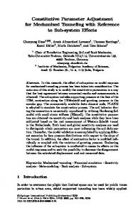
Output voltage, kV 120 110 100 90 80 70 480
500
520
540 560 580 600 Primary storage voltage, V
Fig. 4. The experimental results of adjusting the output voltage of a generator with two magnetic compression links at a 1 kΩ load depending on the voltage of the primary storage.
permalloy with 10 μm thickness. The primary winding w1 = 1 is made of copper tape with a 0.5-mm thickness and a 10-mm width; the secondary winding w2 = 34 is made from PEV-2 wire with 0.8 mm in diameter. The insulation of the transformer magnetic conductor has a multilayer structure and is made of teflon tape; its thickness is 0.1 mm, while the total insulation thickness equals 1.5 mm. Тr2 is produced of a К90 × 50 × 25 mm ring core of 50NP permalloy with a 10-μm thickness. The primary winding w1 = 4 and the secondary winding w2 = 17 is made from PEV-2 copper wire 0.8 mm in diameter. Both windings are wound on an acrylic resin frame with 3 mm thickness. The energy transmitted into the capacitor C4 (0.245 nF) is 0.36 J at the capacitor voltage of 54 kV. The amplitude and the width of the current pulse of direct pumping of semiconductor interrupter are 28 A and 0.81 μs, while the amplitude and the pulse width of the current pulse of inverse pumping are 220 A and 0.1 μs. At a 1 kΩ resistive load the generator creates a voltage pulse with an amplitude of 115 kV, a halfheight width of 58 ns, and a front width of 48 ns. 3. EXPERIMENTAL RESULTS The experiments on the adjustment of the output voltage of a high-voltage nanosecond pulse generator were performed using a laboratory transformer, which was adjusted to the generator supply voltage. Typical oscillograms are shown in Figs. 2 and 3. The TVO-60 resistor with 1 kΩ resistance was used as the load. Thus, the dependence of the output voltage on the voltage at the primary storage was obtained. The experimental results are shown in Fig. 4. As seen
INSTRUMENTS AND EXPERIMENTAL TECHNIQUES
Vol. 60
No. 1
2017
OUTPUT VOLTAGE ADJUSTMENT
from Fig. 4, a change of the voltage of the primary storage capacitor C2 from 450 to 610 V leads to a proportional change of the output voltage from 70 to 115 kV. The voltage range has boundaries. At a further decrease of the voltage of the primary storage below 450 V, the circuits of the magnetic generator are out of the matched mode. The voltage was not increased to higher than 610 V, since the operating voltage of the capacitor C2 is 630 V. CONCLUSIONS Thus, as seen from the experimental results, the adjustment of the output voltage of high-voltage pulse generators designed according to the scheme of a magnetic generator and inductive storage with a semiconductor current interrupter can be carried out by adjusting the primary storage charge voltage. Smooth adjustment of the output voltage in the 70–115 kV range was achieved. The corresponding increase in the pulse repetition rate while reducing the pulse voltage will make it possible to save the average output power of the device. ACKNOWLEDGMENTS This work was performed within the framework of the State job no. 0389 2014 0005.
INSTRUMENTS AND EXPERIMENTAL TECHNIQUES
49
REFERENCES 1. Komyak, N.I., Morgovskii, L.Ya., and Peliks, E.A., Defektoskopiya, 1978, no. 3, p. 108. 2. Fursei, G.N. and Peliks, E.A., Prakt. Silov. Elektron., 2011, no. 44, p. 47. 3. Merkulov, B.P., Mel’nichuk, G.V., Makhan’ko, D.S., and Merkulov, D.P., Oboronnyi kompleks—Nauchnotekhnicheskomu progressu Rossii, 2013, no. 1, p. 44. 4. Rukin, S.N., Instrum. Exp. Tech., 1999, vol. 42, no. 4, p. 439. 5. Filatov, A.L., Korzhenevski, S.R., Kuznetsov, V.L., Ananin, M.V., and Motovilov, V.A., in Proc. 15th Int. Conf. on High Power Particle Beams, St. Petersburg, 2004, p. 552. 6. Kuznetsov, V.L., Korzhenevskii, S.R., Komarskii, A.A., and Chepusov, A.S., RF Patent 130135, Byull. Izobret., 2013, no. 19. 7. Bayankin, S.N., Mozharova, I.E., Korzhenevskii, S.R., Kuznetsov, V.L., and Komarskii, A.A., Vestn. Rentgen. Radiol., 2015, no. 2, p. 42. 8. Meerovich, L.A., Vatin, I.M., Zaitsev, E.F., and Kandykin, V.M., Magnitnye generatory impul’sov (Magnetic Pulse Generators), Moscow: Sovetskoe Radio, 1968.
Translated by M. Kromin
Vol. 60
No. 1
2017