Artificial Neural Networks - Advances in Computational Intelligence and Learning. Bruges (Belgium), 23-25 April 2008, d-side publi., ISBN 2-930307-08-0.
ESANN'2008 proceedings, European Symposium on Artificial Neural Networks - Advances in Computational Intelligence and Learning Bruges (Belgium), 23-25 April 2008, d-side publi., ISBN 2-930307-08-0.
Parallel Asynchronous Neighborhood Mechanism for WTM Kohonen Network Implemented in CMOS Technology Marta Kolasa1 and Rafał Długosz2,3,* 1- University of Technology and Life Sciences, Institute of Electrical Engineering, ul. Kaliskiego 7, 85-791, Bydgoszcz, Poland 2- University of Neuchâtel, Institute of Microtechnology, Rue A.-L. Breguet 2, CH-2000, Neuchâtel, Switzerland 3- University of Alberta, Department of Electrical and Computer Engineering ECERF Building, Edmonton, T6G 2V4, Canada Abstract. In this paper we present an original neighborhood mechanism for WTM self-organizing Kohonen map implemented in CMOS 0.18 μm process. Proposed mechanism is an asynchronous circuit and does not require controlling clock generator. Propagation of an enable signal from a winning neuron to neurons that belong to the winner’s neighborhood is very fast. For example radius (R) of the neighborhood equal to 15, total time that is required to start adaptation of all neighboring neurons is below 10 ns. This makes the proposed WTM network in practice as fast as the WTA Kohonen network. When compared to WTM networks implemented, for example in C++, the proposed solution can be even several hundreds times faster and consume much less power.
1
Introduction
Artificial neural networks (ANN) and their application in various systems have been gaining popularity over last years [1, 2]. One of the reasons is that ANN, simulating the biological structure of the human brain is able to provide proper data classification in situations, where classic controllers fail, e.g. when data is incomplete or when there is an ambiguity due to overlapping of particular data classes. In this work we focus on hardware implementation of the neural network, which has been originally proposed by Teuvo Kohonen in [3]. The Kohonen neural network (KNN) features a competitive, unsupervised learning, which means that network parameters i.e. neuron weights are modified and adjusted without any feedback as is in case of supervised learning methods. Networks of this type are known also as selforganizing feature maps (SOFM). There are two general types of KNNs i.e. winner takes all (WTA) and winner takes most (WTM) networks. WTM provides better abilities e.g. are able to create topographical semantic maps, which is not possible in WTA networks. WTM networks contain the neighborhood mechanism, which is able to eliminate dead neurons more effectively than WTA networks, thus providing better convergence properties. On the other hand WTA networks have simpler structure featuring lower computational complexity and are faster than WTM networks [3, 4]. *
this work is supported by EU Marie Curie OIF fellowship, project No. 21926
331
ESANN'2008 proceedings, European Symposium on Artificial Neural Networks - Advances in Computational Intelligence and Learning Bruges (Belgium), 23-25 April 2008, d-side publi., ISBN 2-930307-08-0.
In our research we focus on hardware implementation of KNN on transistor level, as this approach allows for parallel data processing and lower power dissipation [5, 6] than in networks implemented using e.g. PC software platforms. In this paper we propose an original parallel and asynchronous neighborhood mechanism, which allows for implementation of WTM networks that potentially are as fast as WTA KNNs although they must perform much larger number of operations.
2
Unsupervised learning in WTA and WTM Kohonen networks
The competitive unsupervised learning in KNNs relies on presenting the network with learning vectors X in order to make the neurons’ weight vectors W resemble presented data. For each training vector X both WTA and WTM Kohonen networks determine Euclidean distances (dEUC) between this vector and the weights vectors W in each neuron, which for n network’s inputs are calculated using the following formula:
d EUC ( X ,Wi ) =|| X −Wi ||=
n
∑( x − w l =1
l
il
)2
(1)
The neuron whose vector W is the most similar to the training vector X wins the competition. In WTA networks only the winning neuron is allowed to modify its weights, while in the WTM networks also neurons that belong to the winning neuron’s neighborhood can adapt weights in accordance with the following equation:
Wi ( k +1) =Wi ( k ) +η k ( k )G (i, j )[ X −Wi ( k )]
(2)
where: ηk is the learning rate, whose value is different for winner and for its neighbors, while G(i, j) is the neighborhood function. Different types of neighborhood have been reported [7], which differ in function G(i, j). The neighborhood can be generally classified into geometrical or Gaussian. In this paper we focus on the geometrical neighborhood, where particular neurons have fixed positions in the map as well as determined neighbors [4, 7]. The neighborhood function G(i, j) is in this case given as:
⎧1 G (i , j ) = ⎨ ⎩0
for d N (i, j ) ≤ R for d N (i, j ) > R
(3)
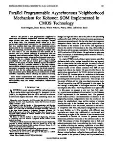
where: dN(i, j) is a distance between the winning neuron and a given neighbor in the map, while R is the radius of the neighborhood [2,4]. During the learning phase radius R decreases from its maximum value, where it covers the entire map, to zero [2, 7]. One of advantages of SOFM is that multidimensional input data can be mapped onto the space with lower number of dimensions, typically 2-D, which allows for better data visualization [4, 7]. In most implementations of KNN rectangular grids of neurons are used, but hexagonal grids that provide even distances between neurons in the map are also used [3]. In this paper we propose a hardware implementation of the rectangular grid of neurons shown schematically in Figs. 1 – 3. Hexagonal grid can be easily implemented in a very similar way. In hardware both types of grid can be realized in one structure and switched over using only several control bits.
332
ESANN'2008 proceedings, European Symposium on Artificial Neural Networks - Advances in Computational Intelligence and Learning Bruges (Belgium), 23-25 April 2008, d-side publi., ISBN 2-930307-08-0.
N
out1 out2 MIN
N
MIN
N
MIN
N MIN
N
N
MIN
N
MIN
MIN
EN
R
N EN R EN
MIN
N MIN
out 3
EN
NEURON EN
N
MIN
WINi and ADDR
N MIN
N
R
EN
R
NEURON EN R
R
R EN
min(outi )
MIN
NEURON
R
MIN
N
MIN
NEURON
NEURON
N EN
MIN
EN
NEURON EN
R
N
R
R
R
R
EN
NEURON
N
EN
EN
NEURON EN
(a)
R
NEURON EN
(b)
Fig. 1: WTM KNN with geometrical rectangular neighborhood function (a) competition between neurons (WTA block) (b) neighborhood scheme.
3
Parallel and asynchronous neighborhood mechanism
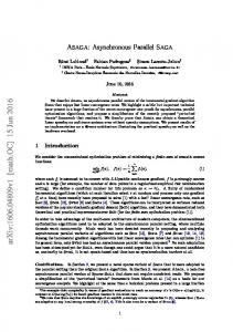
Hardware implementation of KNNs requires a special design methodology. The first problem that is not present in software implementation is placement of neurons in the chip and routing between particular neurons. The initial investigation reveled that placement of neurons like in Fig. 1 is the most natural and at the same time the most optimal looking from the chip area point of view. The simplified neuron’s structure for such a network is shown in Fig. 2. For simplicity, only these blocks that are used to realize the neighborhood mechanism have been shown. Other blocks such as Euclidean distance calculation circuit (EDC) and adaptive weight change mechanism (AWC), described in [5, 6], have been omitted in this scheme. In the presented network each neuron communicates only with eight closest neighbors using 2(i+1) control lines per each couple of neurons, where i is the number of required bits to store the maximum value of the radius R. In the example map with dimensions 16x16 R < 16, resulting in i = 4. One line carries the enable signal EN. As each couple of neighboring neurons can communicate in two directions, therefore the number of lines must be doubled, resulting in factor 2 before brackets. Each winning neuron has also access to the R_PROP signal. Value of this signal is initially set up to its maximal value and then successively decreased to zero during the learning process. Each neuron in the layout is surrounded by two i-bits rings of paths to enable receiving or sending signals in all eight directions. The proposed mechanism works as follows: The winning neuron, whose WTA signal equals to “1” gets the opportunity to program own R signal to R_PROP. This signal becomes the Rout signal from this neuron that is propagated in all directions. At the same time the WTA signal enters the EN_PROP block that is shown in Fig. 3a. As this signal enters all OR gates in this block therefore all winner’s ENout signals become logical “1”. This means that all neurons surrounding the winning neuron gets the opportunity to adapt their weights using own AWC blocks [5], which are triggered by both EN or WTA signals. Particular winner’s ENout signals became the ENin signals in particular neighbors. Note that each neuron in the first ring surrounding the
333
ESANN'2008 proceedings, European Symposium on Artificial Neural Networks - Advances in Computational Intelligence and Learning Bruges (Belgium), 23-25 April 2008, d-side publi., ISBN 2-930307-08-0.
ENin_8 ENout_8
R in_1 ENin_1 ENout_1
R in_8
winner gets only one ENin signal, generating only one or three own ENout signals that are immediately sent to the second ring. Now, when such an ENout signal is sent in one of N, S, W, E directions, then only one ENout signal is generated at the opposite side of the neuron in the next ring. On the other hand when the ENout signal is sent in one of NE, NW, SE, SW directions, then the neuron in the next ring sends its own ENout signals in three different directions. Such distinction is necessary, as the number of neurons in each next ring increases by eight. R in_7 ENin_7 ENout_7
R out
R out R out
R_PROP ENin_2 ENout_2
i- bits i- bits
STOP
R in_2
R in_6 ENin_6 ENout_6 R out
EN_PROP
R out NEURON R out
R out
R in_3
ENout_5 ENin_5
R out ENout_4 ENin_4 R in_4
ENout_3 ENin_3
R in_5 RPROG WTA
Fig. 2: Model of neuron used in WTM Kohonen network shown in Fig. 1. ENout_1
ENin_8 ENout_8
ENin_7 ENout_7
NEURON
ai
ENin_1
EN
ENout_2 ENin_2
STOP
WTA
a2
a1
b3
b2
b1
ENin_6 ENout_6
ENin_5 ENout_3
Rin a3
ENin_3
ENout_4 ENin_4
STOP
bi
Rout
ENout_5
(a)
(b)
Fig. 3: Particular blocks used in proposed WTM neighborhood mechanism to propagate: (a) enable signal – EN_PROP and (b) radius signal – R_PROP. This mechanism causes that enable signal is propagated concentrically from the winning neuron. Direction of this propagation is always from the winner to borders of the map and one neuron never gets EN signal from more than one direction. The problem here is that EN_PROP circuit does not contain the mechanism that can stop the EN signal on a given radius R. To solve this problem another circuit shown in Fig. 3b has been designed. This circuit is used to propagate the radius R, but in this case Rout = Rin-1 in each case (Rin is represented by bits ai, while Rout by bits bi). When Rout reaches zero i.e. all bits “b” are logical “0” then a STOP signal is generated by an EN_PROP circuit that blocks further propagation of the EN signal.
334
ESANN'2008 proceedings, European Symposium on Artificial Neural Networks - Advances in Computational Intelligence and Learning Bruges (Belgium), 23-25 April 2008, d-side publi., ISBN 2-930307-08-0.
Each neuron which gets the ENin signal gets also the R signal from the neighbor. As a given neuron can get R signals from any direction, therefore to avoid collision between particular R signals, which can have different values, the proper R signal is selected using ENin signal and set of switches shown in Fig. 2.
3.1 Simulation results of our designed mechanism Our proposed mechanism enables implementation of the WTM KNN on the basis of the WTA network designed earlier in CMOS 0.18 μm process [5, 6]. This mechanism adds about 110 transistors with small dimensions to each neuron, increasing chip area of each neuron by about 2000 μm2. When number of inputs is equal to e.g. 10, then chip area increases by only 5-6 %. Designed circuit has been verified in HSPICE simulations. As particular signals are digital, therefore this is not necessary to present all waveforms. Fig. 4 presents example results that show dynamic parameters of this circuit. Both EN and R signals are propagated in the network asynchronously and in parallel in all directions. In the worst case scenario i.e. at the beginning of the learning process, when R has the largest value, all neurons in the network start adaptation after the time that is equal to maximum Rmax·tR, where tR is a propagation time of a single R_PROP block. EN_PROP circuit is faster than R_PROP block and does not need to be taken into account in the analysis. In case of Rmax=15 and supply VDD = 1.5 V the total propagation time is equal to about 10 ns, which is about 1% of the time reserved in the WTA network for each vector X, when clock frequency is equal to 1 MHz [6]. Power dissipation during propagation is equal to 40 μW per one neuron, which gives about 0.4 pJ per one neuron. This is below 1 % of total energy consumed by one neuron [6]. Some additional energy is also required to adapt all neighboring neurons.
Fig. 4: Propagation of R signal in R_PROP circuits for Rmax=15 (4 bits). To enable a direct comparison between KNNs implemented in hardware and in software platforms, an example KNN have been also designed in C++. The number of operations (NOP) per one vector X vs. radius R for selected networks dimensions is shown in Fig. 5. Given values are proportional to time that PC needs to calculate each data. In this situation a direct comparison to WTA/WTM KNNs designed in CMOS technology is possible. Experiments show that comparable data rate is when WTM network implemented on both platforms has only 3 neurons with 2 inputs (6 weights). For larger dimensions hardware implemented network can be even several hundreds times faster, for much lower power dissipation. Analog blocks used in CMOS KNNs are relatively slow but work in parallel in all neurons.
335
ESANN'2008 proceedings, European Symposium on Artificial Neural Networks - Advances in Computational Intelligence and Learning Bruges (Belgium), 23-25 April 2008, d-side publi., ISBN 2-930307-08-0.
120 32x32x12 WTM (C++)
NOP [10E3]
100 80
32x32x12 WTA (C++)
60 8x8x12 WTA (C++) 40
16x16x12 WTM (C++)
8x8x12 WTM (C++)
16x16x12 WTA (C++)
20
WTA/WTM(CMOS) 0 0
5
10
R
15
20
25
30
Fig. 5: Number of operations (NOP) vs. radius R for WTA and WTM KNNs.
4
Conclusions
A new asynchronous and parallel neighborhood mechanism designed for hardware implemented winner takes most (WTM) Kohonen neural network has been proposed in this paper. This mechanism has been implemented in CMOS 0.18 μm technology. The main advantage of our proposed solution over the KNNs implemented in software is that the time required for calculation of one output data is in practice the same like in WTA network and additionally does not depend on network dimensions, as all neurons work in parallel. On the other hand in hardware implementation possible network dimensions are limited by the chip area and number of pins. Comparing WTA and WTM networks, implemented in CMOS technology, chip area is in the second case larger by about 5-20 %, depending on number of network’s inputs. Power dissipation of the proposed neighborhood mechanism can be neglected.
References [1]
Lin He, Wensheng Hou, Xiaolin Zhen, Chenglin Peng, “Recognition of ECG Patterns Using Artificial Neural Network”, 6th International Conference on Intelligent Systems Design and Applications, (ISDA 2006), Vol. 2, October 2006, pp.477-481
[2]
E.J. Tkacz, P. Kostka, K. Jonderko, B. Mika, “Supervised and Unsupervised Learning Systems as a Part of Hybrid Structures Applied in EGG Signals Classifiers”, IEEE Annual Conference Engineering in Medicine and Biology, Shanghai, China, Sept. 2005
[3]
T. Kohonen, Self-Organizing Maps, third ed. Springer , Berlin, 2001
[4]
L. Brocki, Recent Advances in Mechatronics, Springer Berlin-Heidelberg, September 2007
[5]
T. Talaśka, R. Długosz, W. Pedrycz, Adaptive Weight Change Mechanism for Kohonen’s Neural Network Implemented in CMOS 0.18um Technology, European Symposium on Artificial Neural networks (ESANN 2007), Bruge, Belgium, 2007
[6]
R. Długosz, T. Talaśka, R. Wojtyna, Hardware implemented Programmable Kohonen Neural Network for Medical Applications, paper submitted to International Symposium on Circuits and Systems (ISCAS), Seatle, United States, 2008
[7]
P. Boniecki, The Kohonen neural network in classification problems solving in agricultural engineering, Journal of Research and Applications in Agricultural Engineering, Vol. 50(1), pp. 3740, Poznań, January 2005
336