Parallelization of Neural Networks using PVM Mathias Quoy1 , Sorin Moga1 , Philippe Gaussier1 , and Arnaud Revel2 1
2
Universit´e de Cergy-Pontoise - ETIS 6, av. du Ponceau, 95014 Cergy-Pontoise C´edex, France
[email protected] , http://www.ensea-etis.fr Ecole Nationale Sup´erieure de l’Electronique et de ses Applications - ETIS
Abstract. We use Neural Networks (NN) in order to design control architectures for autonomous mobile robots. With PVM, it is possible to spawn different parts of a NN on different workstations. Specific message passing functions using PVM may be included into the NN architecture. A graphical interface helps the user spawning the NN architecture, and monitors the messages exchanged between the different subparts of the NN architecture. The message passing mechanism is efficient for real time applications. We show an example of image processing used for robot control.
1
Introduction
Our research group develops architectures for the control of autonomous mobile robots. We take mainly inspiration from neurobiology for designing NN architectures. This work is also based on a constructivist approach. We first build the architecture parts dealing with the inputs processing, and managing some low level behaviors (obstacle avoidance for instance). Like in Brooks subsumption [1], the system consists in a hierarchy of sensory-motor loops: from very fast low level sensory-motor loops (obstacle avoidance, sensor reading ...) to very timeconsuming image analysis and planning procedures. In our system, data issued by these mechanisms are processed by higher level modules which may in return influence them. This architecture is integrated in the perception-action framework (Per-Ac [3]). It is composed of a reflex pathway and a learned pathway. Once learning has taken place, it may override the reflex mechanism. The inputs to the system are the image taken from a CCD camera, infra-red sensors and the direction of the north given by a compass. Each of these inputs may be processed separately. Moreover, some time consuming image processing algorithms may also be performed in parallel. Using a set of workstations, it is clearly not interesting to parallelize the network at the neuron level (one workstation per neuron !), but rather in term of computational pathways (CP) being processed in parallel. Each CP corresponds to a functional part of the global NN architecture and may run on a different workstation. The exchange of information between CPs is most of the time asynchronous. We also want to minimize the number of messages exchanged. We use PVM 1 for spawning the CPs on the workstations 1
Current version used is PVM 3.4.3 for Solaris and Linux
II
and for the message passing libraries [4]. Using PVM has two interests. First, the architectures we have developed become bigger and bigger as the task being performed is more complex. So even if the computational power is increasing, we do not match the real-time needed for our robotic experiments. Second, brain computation follows different pathways in parallel and is also performed in different cortical areas. Thus, it is also interesting to preserve this parallelism in our simulations. PVM is also used at two different levels. First, we have developed specific communication functions integrated in the global architecture indicating the kind of information sent from one NN architecture to the other (Section 2). The specific message passing algorithms described may be used in any real time application, in particular when there is a huge amount of data to deal with. Second, a process manager has been developed. This manager helps the user choosing on which workstations to run the NN architectures, and monitors all message exchanges (Section 3). In section 4, we study the performances of a message passing mechanism used in a NN architecture controlling a mobile robot. This architecture enables a robot to go where it has detected movement in its image.
2
Designing NN architectures
We do not develop here how we construct the NN architecture for performing a particular task (indoor navigation for instance). This is the focus of numerous other papers [2, 8]. We will rather stress how PVM fits in our NN architecture. The design of a NN architecture is performed using a specific program called Leto. It has a visual interface where the user may choose between several different kinds of neurons and connect them together. Not all groups represent neurons. Some may perform specific algorithmical functions (displaying an image on screen, giving orders to the robot ...). Once designed, a Leto architecture may be saved (creating three files: name.script, name.net and name.config), and is run using another program called Promethe (see next section). So, it is possible to design different architectures dedicated to specific tasks. The problem is to exchange data between these different tasks. This is where PVM is used at this level. So we deal here with the design of modules that may be integrated in the NN architecture. These modules tell whom to send a message to, or who to receive a message from. We have coded specific message passing functions using the already existing PVM routines. Our functions are implemented as algorithmical groups in the architecture. There is basically one group sending data in one NN architecture and another receiving data in another NN architecture. The data sent is the neuron values. There may be several different NN architectures running in parallel. And there may be several different sending and receiving groups in each NN architecture. So we need to define where to send and from whom to receive. This is implemented through the definition of symbolic links which must be the same for the sender and the receiver. This symbolic link is coded on the name of the link arriving to a sender or receiving group. This name is composed of two
III
parts: the symbolic name and a number corresponding to the message passing number used by PVM. After having launched all tasks, a symbolic link table is built. This table makes the matching between a symbolic name and a PVM task identifier (tid) number. Then the relevant parts of this table are sent to the different tasks. In order for two tasks to be able to communicate, the symbolic link name and the message number must be the same 2 . Upon reception of a message, the activities of the neurons of the receiving group are the same as the ones of the sending group. Thus, from the receiving group point of view, it is as if it were directly connected to the sending group through a “real” neuronal link. The message passing functions are functionnaly invisible. The different sending and receiving functions are the following: – function send PVM: sends the value of the neurons where it is connected to. The receiver is retrieved using the symbolic link name and the message number. – function receive PVM block: waits for a message (neuron values) from a sender. The sender is identified by its symbolic link and message number. – function receive PVM non block: checks if a message (neuron values) has arrived from the sender. If not, execution continues on the next neuron group. We are running our NN architectures in real time for controlling mobile robots. Depending on the task to perform, it may be very important to have access to up to date information. For instance, computing the optical flow must be performed on the most recent image data. This is not mandatory for object recognition, since it stays where it is. Nevertheless, it turns out that most computations are asynchronous. Because we have to run in real time, we do not want to wait for a task to be finished before continuing the whole computation, and we do not always know which task will run faster or slower. So in the asynchronous processing, there may be two problems: information may be missing in some parts of the architecture, because some computation is not finished yet. Conversely, some parts of the system may run much faster than others and deliver a continuous flow of redundant information. Indeed, if the sending task is running much faster than the receiving one, the receive queue will be overwhelmed with messages. Moreover, the only important message to process is the last sent. It is easy to solve the first problem. If information has not arrived yet, the previous neuron values are used. We suppose there is a temporal coherence in the neural information (internal dynamics of the neuron [5] and use of a neural field [9]). For dealing with the second problem, we have to introduce new message passing functions: – function send PVM ack: sends a message only if the receiver has allowed it by sending an ack message. If the message has not been received, it does not send anything and execution continues on the next group of neurons. 2
The message number is not mandatory. It may be chosen randomly at the symbolic link table creation. But it is easier to know it beforehand for debugging purposes.
IV
– function receive PVM block ack: waits for a message (neuron values) from a sender. Once the message received, this function sends back an ack message to the sender. – function receive PVM non block ack: same as the previous one, but waiting is non blocking. Thus now, a sender may only send information if the receiver is able to process it. The way we have implemented the function, the receiver sends its ack message just after having received a message from the sender. Thus, the sender is now allowed to send a message again. If the sender runs faster than the receiver, it sends its new message before the receiver has been able to finish its computation. So, when it comes back to the receive function, a message is present in its queue, but this message is not reflecting the current state of the sender anymore. An alternative version of the receiving function could be to send the ack before a blocking receive. It is now the receiver which will wait until the sender catches the ack, and sends its message. Thus the message received by the receiver matches now the latest state of the sender, but the sender has to wait for this message. This function is function receive PVM ack block. It avoids saturating the Ethernet link and loosing too much computation time in communication procedures.
3
Running NN architectures
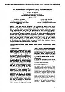
A NN architecture is run using a specific program called Promethe. In each NN architecture, a token is moving from neuron group to neuron group activating them sequentially. When a PVM message passing group is activated, the corresponding function described above is executed. Once all groups have been activated, running resumes on the first group (fig. 1). We have seen that PVM is used as message passing library between tasks running NN (Promethe processes). It is now necessary to have a task manager (Promethe PVM Daemon) spawning all these tasks. In particular, this process has to build the symbolic link table and send it to the NN tasks (fig. 1). In order to achieve this, the user has to define a file (name.pvm) indicating: the task name, the name of the workstation where to run the NN, the name of the NN architecture (.script, .net and .config files). Then, each symbolic link is given with its sending and receiving task. An example of such a file corresponding to the NN described next section is given below: promethe task1 panpan test_2_m.script test_2_m.net test_2_m.config task2 elliot test_2_s.script test_2_s.net test_2_s.config symbolic links
V
firstlink task1 task2 secondlink task2 task1 After having built the symbolic link table, the program displays a graphical interface using Xview. We have included in this interface some helpful features such as: testing the network for the various workstations available, testing the speed of these workstations and ranking them, assigning a task to a workstation, displaying the current state of the tasks (running or waiting), and displaying in real time the messages exchanged between the various tasks. Promethe_PVM_Daemon manager
task1 Promethe
task2
taskN
Promethe
Promethe PVM messages exchanged
token
symbolic link table trace of messages neuron values Neuron group Link between groups
NN architecture Fig. 1. Sketch of the message passing between the task manager process Promethe PVM Daemon and the launched Promethe tasks. Each Promethe task is a NN architecture composed of groups of neurons. A token is moving from one group to the other activating them sequentially.
Assigning a task to a workstation may be done either as specified in the name.pvm file, or on the fastest workstations only, or randomly. All three options are available on line in the graphical interface. A task may also be assigned to a specific workstation by selecting the workstation’s name and then clicking on the task (shown as a square in the display window). The state of the tasks and the messages exchanged are monitored by the task manager. The purpose here is not to have a complete debugging tool. It is rather thought as an help for the user. This help gives two informations: whether a task is running or waiting for a message, and which kind of message has been exchanged between tasks. The first information gives hints about the working load of each task, and the efficiency of the message exchanges. The second infor-
VI
mation allows to follow in real time the messages exchanged between the tasks. Each time data is sent or received, a message is issued to the manager, giving the sending and receiving tids and the message number (fig. 1). So, once all tasks are launched, the manager waits for these messages, and displays the information on screen. The manager also catches all PvmTaskExit signals so that it may resume its activity once all Promethe tasks are over. Monitoring the message exchanges could also have been implemented another way, the manager only waiting for any message exchanged between any tasks, and then sorting these messages depending on the message number. This supposes that all message numbers are different, which is not required if the symbolic links are different.
4
Results
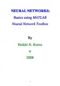
We report here the performance results on a particular robotic experiment. Note that the robot 3 is also a multi-processor system (a micro controller for the speed control and a 68340 microprocessor for the communications with the workstations and the control of the different sensors). This system is not under the control of PVM but it also works in an asynchronous manner. The task of the robot is to learn to imitate a given teacher [7]. At the beginning, the robot can only use motion perception for going in the direction of the moving object (supposed to be the teacher). If this behavior is not associated with a negative reward, the robot also learns the static shape of the moving object, so as to be able to move in its direction even if no motion is perceived. This mechanism is also used to choose between different moving objects [6]. In order to detect movements, the optical flow is computed. In parallel, an object recognition is performed from the matching of local subimages centered around the local maximal curvature points. These feature points correspond to the local maximum of the convolution of the gradient image with a Difference Of Gaussian (DOG) function. A sketch of the parallel architecture used in given figure 2. Task2 performs the feature points extraction and shape recognition. Task1 performs data acquisition, movement detection and robot movement control. These two tasks are not fully synchronized in the sense that task1 is not waiting for the result of task2 for continuing its computation (non blocking receive). However, task2 needs the information from task1 for its computation, because it looks for the feature points only where movement is detected (in the case there is a moving object. In the other case, the whole image must be processed). The data given by task1 to task2 is a 196x144 array of bytes (image) and a 35x25x3 array of floats corresponding to where movement has been detected. Task2 is sending to task1 a 35x25x3 array of floats corresponding to the position of a recognized teacher. We have monitored the execution time in three different cases: the sequential computation (without PVM) of the optical flow alone (will become task1), the sequential computation of the optical flow and the teacher recognition, and the independent computation of the flow (task1) and the teacher recognition (task2). 3
Koala robot built by KTeam SA, Switzerland
VII Task 2
Processing 2 receive_PVM_block_ack
Task 1
Perception
Movement detection
Data acquisition
Processing 1
send_PVM_ack
send_PVM_ack
Action
receive_PVM_non_block_ack
Environment
Fig. 2. Sketch of the computation done by the two tasks. Note that because the receive in task1 is non blocking, the computation effectively executed in parallel is not always what is marked as Processing1 and Processing2. Processing2 may be executed in task2 whereas task1 executes data acquisition and movement detection.
These results are given in the following table (mean-time in seconds is an average on 20 runs on SUN Sparc Ultra 10 workstations (part of a pool of workstations on a 100Mb Ethernet link). Each run corresponds to a new experiment (in particular new input data). Each task is running on a separate workstation.): time in seconds seq. flow seq. flow + recog. PVM seq. mean time 3.06 9.38 task1 mean time (0) task2 mean time (1) par. mean time (max) task1 mean time acquiring data (2) task1 mean time in PVM (sending and receiving) (3) processing 1 (0) - (2) - (3) task2 mean time in PVM (4) processing 2 (1) - (4)
flow + recog. 3.97 2.81 3.97 1.47 0.03 2.47 0.32 2.49
As expected the parallel computation runs faster than the sequential one. In average task2 runs faster than task1, mainly because of the time spent in the communications between the robot and the workstation. Thus as task2 has to wait for data from task1 in a blocking receive, the time spent in PVM functions (in particular waiting for data) is longer. Communications between the robot and the workstation is slow, so it would be particularly interesting to have a process dedicated to this task. These informations may then be dispatched to other processes.
VIII
5
Discussion
The message passing mechanism we have used enables to use PVM for real-time applications. It enables to send a message only when the receiving task is ready to process them, thus reducing the network load level. Some tasks may need specific data in order to perform their computation, others may continue working even if the newest information is not available yet. We have used PVM for parallelizing independent sub-networks composed of several groups of neurons. Some groups contain thousands of neurons. A further speed-up of our system will be the parallelization of the computation inside a group of neurons. We haven’t tested yet whether PVM or threads (sharedmemory) based algorithms should be used. In the later case, we would use multiprocessor architectures (bi or quadra Pentiums for instance). On a bi-processor architecture, set of threads will update different subgroups of neurons and will almost divide by two the computation time devoted to a map of neurons. This work is part of a project dedicated to the development of a neuronal language. Our Leto interface already allows to quickly design NN globally, ie. without specifying by hand each connection for instance. This construction is therefore made on a graphical interface: the user does not to write down his specifications in a file. The difficulty is to provide the user with enough (but not too much) different group of neurons and links between them to choose from when designing his NN architecture. By the time, we begin to have standard neuron groups and links. Moreover, some parts of the architecture are now stable and may be used without any changes for any other robotic experiments. This is the case for the image processing part for instance. A next step will be then to provide “meta-groups” of neurons (the equivalent of cortical areas) regrouping stable functional groups.
References 1. Rodney A. Brooks. A robust layered control system for a mobile robot. IEEE Journal of Robotics and Automation, R.A. 2(1):14–23, March 1986. 2. P. Gaussier, C. Joulain, J.P. Banquet, S. Leprˆetre, and A. Revel. The visual homing problem: an example of robotics/biology cross fertilization. Robotics and Autonomous Systems, 30:155–180, 2000. 3. P. Gaussier and S. Zrehen. Perac: A neural architecture to control artificial animals. Robotics and Autonomous Systems, 16(2-4):291–320, 1995. 4. A. Geist, A. Beguelin, J. Dongarra, W. Jiang, R. Manchek, and V. Sunderam. PVM: Parallel Virtual Machine - A users’s guide and tutorial for networked parallel computing. MIT Press, Cambridge, Massachusetts, 1994. 5. J.A. Scott Kelso. Dynamic patterns: the self-organization of brain and behavior. MIT Press, 1995. 6. S. Moga and P. Gaussier. Neural model of motion discrimination. In ECVP98, Oxford, England, 1998. 7. S. Moga and P. Gaussier. A neuronal structure for learning by imitation. In F. Mondada D. Floreano, J.D. Nicoud, editor, European Conference on Artificial life, ECAL99, volume 1674, pages 314–318, Lausanne, september 1999.
IX 8. M. Quoy, P. Gaussier, S. Leprˆetre, A. Revel, C. Joulain, and J.P. Banquet. A neural model for the visual navigation and planning of a mobile robot. In F. Mondada D. Floreano, J.D. Nicoud, editor, European Conference on Artificial life, ECAL99, volume 1674, pages 319–323, Lausanne, september 1999. 9. G. Sch¨ oner, M. Dose, and C. Engels. Dynamics of behavior: theory and applications for autonomous robot architectures. Robotics and Autonomous System, 16(2-4):213– 245, December 1995.