Feb 5, 2013 ... Design a circuit to provide output voltage of 2.4V. (0.7 V at 1 mA). Small Signal
Model. Microelectronic Circuits,. Sixth Edition. Sedra/Smith.
2/5/2013
Constant Voltage Drop Model • Assume that if the diode is ON, it has a constant voltage drop (0.7V)
Piecewise Linear Model • Constant voltage up to 0.5V then resistor
1
2/5/2013
Ideal Diode Model • Similar to constant voltage drop, but the voltage drop is 0 V
Find ID and VD for VDD = 5V, R=10K Assume 0.7 V at 1-mA Use iteration
2
2/5/2013
Design a circuit to provide output voltage of 2.4V (0.7 V at 1 mA)
Figure E4.11
Microelectronic Circuits, Sixth Edition
Sedra/Smith Copyright © 2010 by Oxford University Press, Inc.
Small Signal Model
Figure 4.13 Development of the diode small-signal model.
Microelectronic Circuits, Sixth Edition
Sedra/Smith Copyright © 2010 by Oxford University Press, Inc.
3
2/5/2013
Solve
Figure 4.14 (a) Circuit for Example 4.5. (b) Circuit for calculating the dc operating point. (c) Small-signal equivalent circuit.
Microelectronic Circuits, Sixth Edition
Sedra/Smith
Copyright © 2010 by Oxford University Press, Inc.
Voltage Regulator (forward bias) • A voltage regulator is a circuit that provides a constant DC voltage even with the changes of the load resistance or the source resistance. • Since the diode in the forward bias region have a constant voltage with relatively large changes in current, it could be used as a voltage regulator
4
2/5/2013
Solve
Figure 4.15 Circuit for Example 4.6.
Microelectronic Circuits, Sixth Edition
Sedra/Smith
Copyright © 2010 by Oxford University Press, Inc.
Solve
Figure E4.15
Microelectronic Circuits, Sixth Edition
Sedra/Smith
Copyright © 2010 by Oxford University Press, Inc.
5
2/5/2013
Zener Diode • Diodes that are designed to operate in the reverse breakdown region. • Used for low current regulators (although regulators chips are widely used now).
Zener diodes • Characterized by – Vz at a specified test current IZT – Maximum power – Knee current IKZ – Incremental (dynamic) resistance rz=V/I
Microelectronic Circuits, Sixth Edition
Sedra/Smith
Copyright © 2010 by Oxford University Press, Inc.
6
2/5/2013
Zener Diodes • Equivalent circuit • VZ0 in practice is the same as the knee voltage
Microelectronic Circuits, Sixth Edition
Sedra/Smith
Copyright © 2010 by Oxford University Press, Inc.
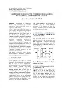
Assume a 6.8-V Zener diode with VZ=6.8 at Iz=5mA, rz=20 , IZK = 0.2 mA, V+ =10V 1V
• Find VO and the line regulation at no load • Find the load regulation when the load current is 1mA • Find VO for R=2 K, 0.5K • Find the minimum load for the diode to operate in the breakdown region
Microelectronic Circuits, Sixth Edition
Sedra/Smith
Copyright © 2010 by Oxford University Press, Inc.
7
2/5/2013
Changing amplitude and Electrical
isolation
ripples Figure 4.20 Block diagram of a dc power supply.
Microelectronic Circuits, Sixth Edition
Sedra/Smith
Copyright © 2010 by Oxford University Press, Inc.
Half-Wave Rectifier • Removes the negative voltage half cycle • Peak inverse voltage 1, but we concentrate of k