Participatory design and model-based approaches are two major HCI design ..... Figure 1, using a webcam with the ARToolkit enables the detection of physical ...
Premières journées de l’AFRV
13 et 14 novembre 2006, Rocquencourt
Participatory Design Meets Mixed Reality Design Models: Implementation based on a Formal Instrumentation of an Informal Design Approach Dubois E. 1, Gauffre G. 1, Bach C. 1, 2, Salembier P. 2 IRIT LIIHS1 / GRIC2, 118, route de Narbonne, 31062 Toulouse Cedex 9 {Emmanuel.Dubois; Gauffre, Bach, Salembier} @ irit.fr that involve the participation of users and are only a subset of the usability methods supporting HumanCentred Design [2]. Concretely, a splitting of the Participatory Design process into four steps, as described in [3], has been adopted and each of these steps is instrumented with several methods: 1) "user's observations" in situ with probes or in vitro within labs, 2) "ideas generations" with brainstorming or focus group, 3) “prototyping” with paper, video or mock-ups, and 4) “Evaluation” with user's test or speak aloud. In comparison with other kinds of human-centred design approaches, Participatory Design specificity is the systematic use of creativity methods involving the active participation of users to generate ideas. The purpose is to identify interactive solutions for specific needs. Creativity methods are considered as informal or projective techniques for revealing in concrete terms the shapes of future systems whished by users. In other terms, these methods have a strong revealing power and constitute a way to generate useful and usable shapes of prototypes, good candidates to resolve requirements defined during observations steps of the Participatory Design. Creativity methods are sometimes considered to have an uncertain efficiency, to introduce biases and also to be used for marketing rather than scientific motives. But in our opinion one questionable assumption of Participatory Design is that it holds the point of view that detailed descriptions of the interactive components of the system as superfluous in the early phases of the design process [4]. The data collected during the creativity phases are then represented in a non formal way (for example drawings, collages, role lists … ).
ABSTRACT: Participatory design and model-based approaches are two major HCI design approaches. Traditionally opposed, the first ones promote user's creativity while the second ones support a more systematic approach of the design space. In Mixed Reality domain, combining these two aspects is especially crucial in order to support the design and to help the users to take into account the wide variety of emerging technologies. We introduce in this paper a solution to bring these two approaches together. In addition, we illustrate how the outcomes of this combination of formal and informal approaches serve as input for the implementation of the designed solution. Key words: design method, mixed reality, focus group, UI modelling, software modelling 1
INTRODUCTION
As illustrated in [1] the term Mixed System has been defined to denote every kind of interactive systems that combine physical and digital worlds: TUI, Augmented Reality, Mixed Reality, etc. Initially confined to specific applications domains such as military, surgery and maintenance, more and more areas try to adopt this interaction mode: games, museum, education, tourism, etc. In order to face this rapid expansion, prototype based development approaches are no longer sufficient and there is a crucial need to define design processes. Traditionally, two forms of design approaches can be met in the field of interactive systems. The first one focuses on human-centred approaches and aims at understanding user's needs in a comprehensive way. The second one is more formal: it aims at structuring the design space and generating conceptual models in order to facilitate the transition between the requirements analysis phase and the development phase. It mainly relates to software engineering considerations. Most of the time, these two approaches are used in a concurrent manner, by experts of different domains. In this paper we present an articulation of an informal design method, the focus-group, with a formal design model for mixed systems, the ASUR model. We show how the formal representation tool can be used as a resource for guiding the management of the FocusGroup, and how the outcome is directly reusable and beneficial in further steps of a development process. Before motivating the need for participatory design and modelling to connect rather than to compete, we introduce existing design approaches of both domains.
1.2 Mixed System Design Approaches To overcome the development of multiple prototypes that mainly aims at proving the technical feasibility to combine new technologies, different design approaches has been explored in the field of mixed systems. A first set of approaches aims at supporting the development of mixed systems. Many ready-to-use libraries have been developed to support specific features such as video-based marker tracking [5], gestures recognition [6], physical data sensing [7], etc. More than a support to the integration of various technologies, development environments have been worked out. For instance, AMIRE [8] and DWARF [9] offer a set of predefined components, patterns and connection facilities. Extension mechanisms are not clearly stated but such approaches provide the developers with a structured view of the application. Finally, additional works aim at connecting these advances with existing standardised tools (Director), or format (SVG). A second set of approaches aims at better understanding and exploring the mixed system design
1.1 Participatory Design Approaches Participatory Design approach is a particular form of the more generic Human-Centred Design process. The main originality of Participatory Design is that it relies on an iterative approach. In addition, it relies on methods
3
Premières journées de l’AFRV
13 et 14 novembre 2006, Rocquencourt
solution. The TAC paradigm [10] and MCPrd [11] architecture describe the elements required in Tangible User Interfaces: one focuses on the description of physical elements while the second focuses on the software structure of TUI. Trevisan [12], ASUR [1] and IRVO [13] are models that aim at supporting the exploration of the design space: they are based on the identification of models, entities, characteristics and tools relevant for a mixed system. Finally, more recent works try to link mixed systems design and implementation steps. [13],[14] propose two different solutions to project scenarios on two different software architecture models while [15] combine Petri Nets and DWARF components. High level of abstraction, component based approach, tools interoperability and implementation support constitutes the main challenges of today's mixed system design approaches.
2
ASUR MODEL
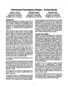
ASUR supports the description of the physical and digital entities that make up a mixed system and the boundaries among them. ASUR components include adapters (Ain, Aout) bridging the gap between both digital and physical worlds, digital tools (Stool) or concepts (Sinfo, Sobj), user (U) and physical tools (Rtool) or task objects (Robj). Arrows are used to express the physical and informational boundaries among the components. On the basis of previous works in the domain, design-significant aspects have been identified: ASUR characteristics improve the specification of components (perception/action sense, location, etc.) and relationships (type of language, point of view, dimension, etc.). A detailed list of components and relationships characteristics is presented in the ASUR-Metamodel [18]. Let us illustrate ASUR with a scenario. The user, User_0, handles and moves a physical object (Rtool-Cup) that is localised by a camera (Ain – Camera, action sense = physical action). The camera produces a picture (Sinfo – Video) and the cup position that will cause a deformation on the 3D object of the task (Sobj – 3D object), of which the cup is a physical representation. If the user press the other adaptor (Ain – touch sensor, action sense = physical action) data that modifies the interaction mode (Stool – Mode) is generated: its value set the deformation (rot., trans. or scaling) to apply on the 3D object. Video, 3D object and interaction mode are carried out by the output adaptor (Aout – Screen, perception sense = visual). Figure 1 shows the resulting ASUR model, within GUIDE-ME [19]. In addition to manipulation tools, GUIDE-ME offers features dedicated to ASUR (patterns manipulation) and mixed system (ergonomic properties checking/definition). The model presented above corresponds to an existing mixed system; section 3 shows how to insert ASUR in a FocusGroup to generate design solutions.
1.3 Interlacing rather than Comparing As mentioned above, Participatory Design approaches support the elicitation of user's requirements by promoting the role and implication of the user during the design process: user may express a requirement, take part in the elaboration of design solution, test the solutions and identify new requirements. So far, existing Mixed Systems Design approaches adopts either a model-based approach or a technology-driven development process. In order to take advantage of the user's participation and outcomes of design models and software tools, combining these two approaches seems unavoidable. But between these somewhat informal expression and collect of user's requirements and, the traditionally more formal design and implementation considerations, translation happens to be quite hectic. One of the main reason that creativity and user's implication are greatly supported by informal approaches, while formal HCI models and tools constitute a solid framework to describe and constrain design solutions. Combining the rigour of formal approaches with the revealing capabilities of informal approaches constitutes a critical challenge. Participative simulation [16] has been proven to install and inject dynamism into a creative space. Similarly, in the context of mixed system design, we assume that joining together formal and informal approaches will facilitate the identification of design solutions and widened the exploration area. Indeed, in order to generate many ideas, informal techniques, such as the focus-group, usually rely on a set of points of interest to consider during the ideas elicitation phase [17]. But in the context of mixed systems, the points of interest must cover all the specificities and richness of possible mixed interaction situations. In order to systematise the exploration of all the different aspects, a formal approach will be helpful to present these multiple characteristics. In addition, there is a growing up interest in mixed systems, but every design participant is still not very familiar with them. Providing the participants with a formal presentation of what a mixed system is, will help them identify new possibilities, thus widening the explored design space. We thus introduce in section 3 the instrumentation of a focus-group method with the ASUR model, a formal description of user's interaction with a mixed system briefly presented in section 2. Section 4 illustrates how to build upon the results of this articulation in further steps of the development process. Finally, we present some perspectives that constitute research avenues directly related to the work presented here.
Figure 1. ASUR model of the scenario, within GUIDE-ME.
3
ASUR-BASED FOCUS-GROUP
Using the ASUR model as a support to guide and stimulate participants of a Focus-Group is made of ten steps. The five first steps are completely independent of the ASUR model and are similar to the first steps of a traditional HCI process: definition of task, domain and dialog models. The five others are specific to Mixed Systems: due to the presence of two worlds (physical and digital) identifying roles of the different objects and forms of exchange of data is very important. Moreover the amount of possibilities is very high and justifies the need of specific design steps to refine them. In this work, the remaining steps of the process are related to ASUR but might be linked to other models. We detail and
4
Premières journées de l’AFRV
13 et 14 novembre 2006, Rocquencourt
illustrate these ten steps in the following paragraphs, on the basis of the previous scenario.
The next steps correspond to the traditional definition of the interaction model, the correspondence between domain concepts (step 3) and interaction objects (GUI, speech, etc.). With mixed systems, the amount of possible interaction objects is very large: discussions within a focus-group are thus hard to control and to get focused. Linking the "formal" ASUR model within the next steps aims at supporting systematic exploration of design solutions. The sixth step focuses on the digital concepts identified in step 3 and aims at attributing to each of them one of the 3 possible kinds of ASUR digital component (S component). They can be: 1) Digital object of the task (Sobj), such as the 3D object in our scenario; 2) Digital information (Sinfo) depicting a decor, help, data or feedback; in the initial version of our scenario, no such digital component is present. 3) Digital tool (Stool): its state influences other digital components, such as the interaction mode in our scenario that has an effect on the deformation to apply to the 3D object. The seventh step aims at identifying output and input ASUR adapters (Aout and Ain) required to support the data transfers identified respectively in steps 4 and 5. A first iteration basically conduces to the elicitation of one adapter for each data transfer identified. The role of the moderator is to help the participants identifying data transfers that might be managed by the same adapter: such decisions reduce the range of the design solutions. In our scenario, one output adapter is sufficient to transfer the interaction mode and the 3D object to the physical world. But the participants preferred to separate the input adapters carrying the mode and size of the deformation. The eighth step aims at characterising the data transfer to the physical world, i.e. the ASUR relationships originating from a component Aout. This consists in setting up a language to spread the data and it corresponds to the definition of one value for each ASUR characteristics of ASUR entities (components or relationships) involved in the data-transfer. For example in our scenario, the perception sense of the Aout and the type of language of the relationship between the Aout and the User must be defined. In order to explore all the possible solutions, the role of the moderator is to encourage the participants to go through the different ASUR characteristics. The moderator has to ensure that a systematic exploration of the characteristics is done. Of course, major adapter characteristics constrain some characteristics of other components and relationships: the "visual" perception sense is incompatible with the speech type of language of relationship. For each value associated to a major characteristic (e.g. perception sense = visual), a formatted table is proposed to the participants to collect possible solutions under this constraint. The table contains possible values of every other characteristic (type of language = text, picture, video, graphic, etc.), comments of the participants, illustration and reason of acceptance or rejection. Combinations of lines of a table represent design solutions for the considered adapter. Such combinations constitute ASUR patterns in Guide-Me [19]. The ninth step is symmetrical to the previous step: it aims at characterising the data transfer to the digital world, i.e. the ASUR relationships aimed at a component Ain. In our case we could identify gesture, speech or keyboarding as type of language to transfer interaction mode and deformation to the computer system. The same formatted tables are used to collect the outcomes.
The first step aims at introducing the context of the session. The context is made of a design model and the application domain for which a mixed interaction techniques has to be designed. Moderator of the session must introduce both of them using illustrated examples (e.g. section 2), story-boards to expose the application. In addition, a representation of the ASUR meta-model [18], including all entities and characteristics must be provided to the participants as a support for the following steps. The second step is common to all HCI method: participants have to clearly analyse the user's task. Indeed, an ASUR model is helpful to describe user's interaction during one task. In order to take advantage of the ASUR model during a Focus-Group, it is crucial to decompose the main task into sub-tasks, clearly defined and understood by all participants. In addition, the moderator makes sure that the granularity of the decomposition is adapted to the ASUR model: according to the ASUR model, this means that only one object of the task exist. In our scenario, the task for which an interaction technique had to be designed consists in "deforming a 3D object". This sub-task was part of a larger project, in which artists had to define a posture to a digital puppet by deforming each of its limbs. The third step aims at identifying domain concepts. In the case of mixed systems, domain concepts may be 1) digital concepts representing domains concepts or interaction concepts (navigation, feedback, etc.) or 2) physical objects representing domains concepts or objects involved in the task realisation (table, pen, bricks, etc.). One may want to consider the existence of mixed object, but in our opinion, it is solely the user's interaction with an object that may be enriched. As a result, we prefer to consider the design of a mixed interaction situation or technique, with objects that are in essence either physical or digital. Based on a task decomposition to a granularity compatible with the ASUR model and produced in step 2, the moderator highlights the concepts and participants may precise the definition. In our scenario, relevant concepts are the 3D object and the interaction mode depicting the deformation to apply (rotation, translation, scaling). Other concepts may appear in the next steps of the process: for example, depending on the interaction techniques used to apply the deformation, an interaction feedback might be required, such as the video feedback of the proposed solution (cf. section 2). This illustrates the ability of our process to be used iteratively. The fourth step aims at identifying the data that must be made perceivable in the physical world during the realisation of the task. Only the data flows must be identified. The moderator has to avoid any discussion related to the data representation (sound, text, colour, etc.) and ensure that every domain concept identified in step 3 is made perceivable at least one time. In our scenario, the interaction mode and the limb (3D object) have to be transferred to the physical world. The fifth step is symmetrical to the previous one: it consists in identifying data flows aimed at the computer system. Without discussing the language used to transfer data, the moderator must ensure that every data provided by a user (position, data-capture) or the physical world (environmental data, physical object) is listed. In our scenario, required data flows carry the interaction mode and the deformation to apply.
5
Premières journées de l’AFRV
13 et 14 novembre 2006, Rocquencourt
The tenth step aims at "breaking" relationships connected to Ain and Aout by inserting new entities. For example, instead of conveying the deformation by way of gesture as suggested in step 9, our final design solution rely on the spatial position a physical cup (Rtool).
the terms of the MVC pattern [1] to decompose the ASUR-IL entities: o The Model of an entity contains data and rules specific to the application and may communicate with other component of the application kernel not directly related to the interaction. It represents a part of the functional core of the system (Fig. 2, bmiddle). o Views of an entity define the model representation that will be perceived by users (Fig. 2, b-right). Depending on the chosen representation, additional elements might be required such as containers for example: their identification and definition is entirely left to the software designer. o Controllers of an entity (Fig. 2, b-left) are in charge of the data input to the entity. They are in charge of collecting and adapting data emitted by ASUR-IL adapters or entities. • Data exchanges: communication between internal elements of an interactive system must not interfere with the user's interaction. Therefore, ASUR-IL data exchanges are asynchronous. The use of events constitutes a solution to implement this communication and ensure the components independence. Building an ASUR-IL diagram from an ASUR modelling of a design solution, is based on the transformation of ASUR adapters, S components and relationships into ASUR-IL adapters, entities and dataexchanges. ASUR adapter transformation results into an ASURIL adapter. It leads to the definition of the triplet and it is constrained by the ASUR adapter characteristics action sense (physical action or language) and perception sense (view, audio, tactile, etc.). Once the triplet is identified, required or generated data is known. In the design solution of our scenario presented in Figure 1, using a webcam with the ARToolkit enables the detection of physical motion of the cup, as required by the ASUR model (Ain-Camera, action sense=physical action). Similarly phidget sensors and API satisfy the second Ain that appears in the ASUR model. In output, we choose to translate the ASUR adaptor (Aout, perception sense = visual) into a screen, a windowing system and the Java SWING API. In addition, a window that contains graphical data is required (see left and right bottom corner of figure 3).ASUR S component transformation results into an ASUR-IL entity. It is constrained by the type of the component: Sobj, Stool or Sinfo. A component Sobj (3D object) is transformed into one model with a number of connection ports equal to the number of data manipulated by the model. One or several views and controllers may be connected to the identified ports. In our scenario, we choose to represent position and state of the 3D object in a common 2D graphical view (Figure 3, middle). A component Stool (interaction mode) is not linked to the functional core of the application
The articulation we propose of ASUR and a FocusGroup covers the main models traditionally considered in HCI design: task and domain models (Step 2 and 3), presentation and dialog models (steps 4-9). But the ASUR model is limited to the description of one task: in order to fully cover a mixed interaction situation, several iterations of this process have to be conduced. Further work will focus on possible optimisation of the process, especially concerning the order in which ASUR characteristics has to be considered. Using this process results in a combination of • the participant's spontaneous implication, • a support to the exploration of a very wide domain that makes it easier to the participants to consider different solutions, and • a structured support to collect the outcomes, i.e. the design solutions envisioned by the design team. This structured support to collect the outcomes makes it easier for designer to integrate these results in the development process. Indeed, we illustrate in the following section how the ASUR-based expression of the outcomes is directly reusable for the implementation of the designed solutions. 4
ASUR-BASED SOFTWARE DESIGN
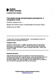
So far, the ASUR model appears to be a good support for the elicitation of design solutions, through the exploration of a set of predefined characteristics. However, its high level of description does not provide any information for software development. In order to increase the power of the ASUR model with regard to the development process, we are developing an extension of the ASUR model: ASUR Implementation Layer (ASURIL). For each interactive task modelled in ASUR, a corresponding ASUR-IL diagram identifies software components required to implement this specific task: • ASUR-IL Adapters (Fig. 2, a): they correspond to the ASUR adapters (step 7, section 3) and fulfil the same role. They represent input and output devices used to perform the task and enclose platform, drivers and libraries. This decomposition facilitates the evaluation of the system portability and highlights the data types provided by the libraries. • • Entities: they correspond to the digital objects involved in the interaction between a user and a mixed system (step 3, section 3). Input/Output in this context correspond to bridges among physical and digital worlds. Rather controversial in traditional UI, the Input/Output separation appears to be technologically and/or spatially present in mixed interaction. As a result, we chose to adopt
a)
< Devices >
b)
Figure 2. ASUR-IL elements.
6
- -
Premières journées de l’AFRV
13 et 14 novembre 2006, Rocquencourt
Its ASUR-IL Transformation is thus only composed of a controller and a view (Fig. 3, bottom center). A component Sinfo transformation depends of its role: • Feedback: the MVC decomposition is no longer required since it just consists in translating a data-flow from one form to another. This is for example the case of the video feedback provided by the ARToolkit. • Data or help: one model and one or more views and controllers are used. • Decors: one model and one or more views are used. One controller may be useful to capture a query but it is not always required. ASUR relationships “data exchanges” between ASUR adapters and S components are transformed into an ASUR-IL data-exchange between the corresponding ASUR-IL adaptors and entities. For example, the ASUR relationship between the Mode and the 3D object (Figure 1) has been transformed into the data exchange between the Controller of the Mode and the Controller of the 3D Object (Figure 3). Other ASUR relationships are not present in ASUR-IL diagrams, because they implies physical parameters (constraints, data-exchange) that are out of the ASUR-IL scope. But, "representation links" (dashed arrow) may have an influence on the design option selected to implement views and controller. More generally, values of ASUR relationships characteristics (point of view, dimension, language type) have an impact on views and controllers. For example, if the type of language specified for the ASUR relationship carrying information to the user about the interaction mode is textual, a 2D graphic should not be the implemented solution. ASUR-IL does not support the precise .
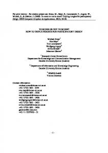
description of the content and behaviour of controllers and views: such constraints must be taken into consideration by the developer with respect to the ASUR characteristics expressed in the model. Following the ASUR-IL decomposition, the role of the developer is to implement or reuse one software component for each ASUR-IL element and to assemble them. Changing one characteristic (or more) in the initial ASUR modeling, directly impacts on the ASUR-IL diagram. Since each element of this diagram correspond to a single software component, the modified areas of an ASUR-IL diagram clearly identify which part of the system implementation has to be modified. Component to remove or introduce are thus easily identified and the implemented mixed system can rapidly evolve. Figure 4 illustrates the assembly of software components corresponding to the ASUR-IL diagram presented in Figure 3. This assembly has been composed within the "WComp Assistant" [21], a component-based platform for wearable computing rapid prototyping. Each software component implemented follows the WComp specification which uses JavaBeans and Java events as interfaces. Using the introspection mechanism, it becomes easy to identify component interfaces and then to create the assembly specified by ASUR-IL Further works will focus on data-exchange characteristics (synchronism, parameter, etc.) and conditions of use of several views and controllers onto a single model. Finally, to facilitate the use of ASUR-IL, the integration of this notation into GUIDE-ME is unavoidable
Video Canvas 3D Object Cont-Object
- Position - State
View-Object State Bar Window
Cont-Mode
View-Mode
JarToolKit
Phidgets
Windows / USB
Windows / USB
Windows
WebCam
Touch Sensor
Screen
Swing
Figure 3. ASUR-IL diagram built from the ASUR diagram of Figure 1.
Figure 4. ASUR-IL identified components implemented and running in WComp platform
7
Premières journées de l’AFRV
13 et 14 novembre 2006, Rocquencourt
[2]
5
CONCLUSION AND PERSPECTIVES
We have presented in this paper how the use of a formal representation tool, (ASUR model), can complement and support a traditional method of Participatory Design, (Focus-Group). By interlacing them, we keep advantages of both and tend to address some limits: guiding the generation of ideas, supporting the structuring of the outcomes of the Focus-Group, providing the experts of the design team with a common and easy access to a formal model. Beyond the crucial interlacing of user centred and model based approaches, we also have presented and illustrated how outcomes of this combination are integrated in the rest of the development process. Firstly using GUIDE-Me patterns leads to the modelling of the whole system. Secondly, the ASUR-IL notation supports the identification of software components required to implement the ASUR designed solution. Transformation rules from ASUR models to ASUR-IL diagrams have been developed and ensure a tight link between early design phases and implementation steps as demonstrated by the implementation of our ASUR-IL description with the WComp platform. Further work is required at two levels. At a first level, the use of ASUR-Focus Group articulation in concrete design situations has shown that it supports ideas generation. But additional evaluations are required in order to quantify these benefits and identify additional tools required to instrument these sessions. At a second level, the description of ASUR-IL elements connection must be refined in order to express specific requirements such as synchronism, data-flow format and communication type, but also to include considerations related to the combination of several views and controllers on a unique model. There is also a need to investigate the combination of several tasks onto ASUR models and ASUR-IL diagrams fusion. Eventually additional translations rules have to be developed in order to take into account all the existing ASUR characteristics. To this end, we believe that transformation mechanisms of Model-Driven Engineering will be helpful. Finally, articulating design specific methods seems to be required to assist the development process of mixed system. We believe that similar articulations are required to include other aspects of traditional HCI methods such as task model and dialogue model. Exploring MDE and in particular the weaving dimensions constitutes a promising way we are now exploring.
[3]
[4]
[5]
[6]
[7] [8]
[9]
[10]
[11]
[12]
[13]
[14] [15]
[16]
[17]
[18]
[19] [20]
REFERENCES [1]
Dubois, E., Gray, P.D., Nigay, L. (2003). ASUR++ : a Design Notation for Mobile Mixed Systems. Interacting with computers (15), p. 497-520.
[21] [22]
ISO / TS 16982. Ergonomics of human-system interaction – Usability methods supporting human-centred design. 2000. Mackay, W.E., Ratzer, A., and Janecek, P. (2000) Video artifacts for design: Bridging the gap between abstraction and detail. DIS 2000, Brooklyn, New York. ACM Press. Bodker, K., Kensing, F., & Simonsen, J. (2004). Participatory IT design - Designing for business and workplaces realities. Cambridge, MA: The MIT Press. Kato, H., Billinghurst, M. (1999). Marker Tracking and HMD Calibration for a Video-Based Augmented Reality Conferencing System. IWAR’99, San Francisco, USA, p. 85. Hong, I.J., Landay, J.A. (2000). SATIN: A Toolkit for Informal Ink-based Applications. UIST 2000, San Diego, USA, p. 63-72. Phidgets Inc. : http://www.phidgets.com Haller, M., Zauner, J., Hartmann, W., Luckeneder, T. (2003) A generic framework for a training application based on Mixed Reality. Tech. report, Upper Austria University of Applied Sciences, Vienne. Bauer, M., Bruegge, B., Klinker, G., MacWilliams, A., Reicher, T., Riß, S., Sandor, C., Wagner, M. (2001) Design of a Component-Based Augmented Reality Framework. ISAR’01, New York, USA, p. 45-54. Shaer O., Leland N., Calvillo-Gamez E. H., Jacob R. J. K. (2004) The TAC paradigm: specifying tangible user interfaces. Personal and Ubiquitous Computing 8.5, pp. 359-369. Ishii H., Ullmer B. (2000) Emerging Frameworks for Tangible User Interfaces. IBM Systems Journal 39, p. 915931. Trevisan D. G., Vanderdonckt J., Macq B. (2005) Conceptualising mixed spaces of interaction for designing continuous interaction. VR’05, Bonn, Germany, 2005, p. 83-95. Delotte, O., David, B., Chalon, R. Task Modelling for Capillary Collaborative Systems based on Scenarios. Actes de TAMODIA, Prague, Rep. Tchèque, 2004, pp. 25-31. Renevier, P. PhD Thesis of Université Joseph Fourier, Grenoble 1, France, 2004. Hilliges, O., Sandor, C., Klinker, G. (2006) Interaction Management for Ubiquitous Augmented Reality User Interfaces, IUI'06, Sydney, Australia, to appear. Guyot, P., Drogoul, A., Lemaître, C. (2005). Using emergence in participatory simulations to design multiagent systems. AAMAS’05, Utrecht. 5 pages. Krueger, R.A., Casey, M.A. (2000). Focus Groups: A Practical Guide for Applied Research, Sage Publication Publisher, 320 pages. Dupuy-Chessa, S., Dubois, E., (2005) Requirements & Impacts of Model Driven Engineering on Mixed Systems Design. IDM'05, Paris, p. 43-54. GUIDE-ME: http://liihs.irit.fr/guideme Krasner, G.E., Pope., T. A cookbook for using the ModelView-Controller User Interface Paradigm in Smalltalk-80. Journal of Object Oriented Programming, 08/1988, pp. 2649. WComp : http://rainbow.essi.fr/wcomp/web/
NOTE: This paper has been published in the Proceedings of the International Conference on Computer-Aided Design of User Interfaces V, Bucharest - Romania, 06/06/2006-08/06/2006, G. Calvary, C. Pribeanu, G. Santucci, J. Vanderdonckt (Eds.), Springer-Verlag, Information Systems Series, p. 71-84, juin 2006.
8