are helped by a set of intermediate terminal nodes to deliver the data from the source to the destination. The relay nodes function using amplify-and-forward (AF) ...
500
IEEE TRANSACTIONS ON WIRELESS COMMUNICATIONS, VOL. 11, NO. 2, FEBRUARY 2012
Performance of Amplify-and-Forward Systems with Partial Relay Selection under Spectrum-Sharing Constraints Ka¨ıs Ben Fredj, Student Member, IEEE, and Sonia A¨ıssa, Senior Member, IEEE
Abstract—This article focuses on the performance of a relay system in spectrum-sharing context. We consider that a secondary user (SU) is allowed to share the spectrum band with a primary user (PU) as long as it meets predefined interference constraints set by the PU. We suppose that the SU’s transmitter and receiver are unable to communicate directly and, thus, are helped by a set of intermediate terminal nodes to deliver the data from the source to the destination. The relay nodes function using amplify-and-forward (AF) and a single “best” intermediate node is selected among a cluster by means of partial relay selection (PRS) technique to relay the information to the destination. Statistics for the end-to-end signal-to-noise ratio (SNR), namely, the probability density function (PDF) and the moment generating function (MGF), are derived and used next to evaluate the bit error rate (BER) of several modulation schemes. Numerical results and interpretations complete the study. Index Terms—Cognitive radio, spectrum sharing, partial relay selection, bit error rate, moment generating function, Rayleigh fading.
I. I NTRODUCTION
W
ITH the emergence of new multimedia applications and the need for mobile Internet, robust communications and higher data transmission speeds are the keys of next-generation wireless technologies. In order to allow the continuous and rapid technological evolution, the demand for new dedicated spectrum bands has become critical. In fact, the rigid allocation of spectrum bands have led to the problem of inefficient use, both in space and time, of the spectrum resources as highlighted by the federal communications commission (FCC) in [1], thus requiring a better utilization of the available resources. Based on software defined radio which uses softwarebased components, cognitive radio (CR) [2] has recently been accepted as a technology that would help exploit the inefficient use of the radio spectrum. The wireless terminal using CR will be able to share a spectrum band with the licensed users considering some restrictions on the interference induced at the latter’s receivers. In this context, a new approach presented in [3] proves that a constraint on the received power at a third party’s receiver is more relevant than a constraint on the transmit power. This idea has been shown to be a good approach for reducing harmful interferences on licensed user’s receiver in a spectrum-sharing context. The secondary user
Manuscript received December 17, 2010; revised June 16, 2011 and October 24, 2011; accepted October 25, 2011. The associate editor coordinating the review of this paper and approving it for publication was G. Colavolpe. This work was supported by a Discovery Grant from the Natural Sciences and Engineering Research Council (NSERC) of Canada. The authors are with the Institut National de la Recherche Scientifique (INRS), University of Quebec, Montreal, QC, Canada (e-mail: {kais, aissa}@emt.inrs.ca). Digital Object Identifier 10.1109/TWC.2011.120911.102240
(SU) power adaptation policy in addition to the random nature of the channel render the communication process between the SU’s transmitter and receiver quite difficult, besides causing possible cuts in the link between the source and the destination. An intermediate node is then necessary to avoid these situations [4]. The concept of relaying, introduced in [5], has proved to be drastically efficient in improving the efficiency and the capacity of communication systems, by using intermediate entities that help carrying the information from the source to the destination. Moreover, it helps overcoming frequent communication-failure situations, such as those where the source and the destination cannot directly communicate: a relay terminal is then necessary to carry the information at both sides of the communication. In this context, several simple protocols for the relay terminals, such as decodeand-forward (DF) and amplify-and-forward (AF), have been proposed [6]. AF consists in amplifying the signals at the relay node and forwarding them immediately to the destination. Taking advantage from the benefits of relaying, effective [7], ergodic and outage [8] capacities of spectrum-sharing constrained systems have been derived for different fading and shadowing environments. Moreover, when multiple relay nodes are involved in the system, the transmission speed and bandwidth efficiency can be improved using relay selection algorithms such as opportunistic relaying (OR) or partial relay selection (PRS) [9]. DF and PRS techniques are combined in [10] to more efficiently use the available resources, i.e., power, rate and bandwidth. While statistics for relaying systems in non-cognitive context have been fairly understood, the AF method calls, sometimes, fairly extensive mathematical calculations. The derivation of some statistics can become extremely difficult when the random variables describing the channel’s gain turn more complex, essentially, in cognitive context. Nevertheless, a quite simple method, based on the properties of the moment generating function (MGF), has been proposed in [11] to compute end-to-end statistics of a PRS system. With the benefits of PRS and the simplicity of AF relaying, we herein combine both techniques to study the performance of a relaying system using PRS in Rayleigh fading environment under peak and average power constraints at a third party’s receiver. We derive the end-to-end signal-to-noise ratio (SNR) statistics, first by finding the probability density function (PDF) then by deriving the MGF. The latter being related to the symbol error rate, it is thereafter used to study the performance of the relay-based spectrum sharing system considering simple modulation schemes, namely, coherent binary phase-shift keying (BPSK) and binary frequency-shift keying (BFSK).
c 2012 IEEE 1536-1276/12$31.00 ⃝
BEN FREDJ and A¨ISSA: PERFORMANCE OF AMPLIFY-AND-FORWARD SYSTEMS WITH PARTIAL RELAY SELECTION UNDER SPECTRUM-SHARING . . .
� R1 ℎSR1 Broadcast
S ℎSP
� R𝑖
ℎSR𝑖 ℎSR𝐿
�� �
� R 𝐿
ℎR𝑖 P
�
ℎR𝑖 D
�� �
�
D
�
P
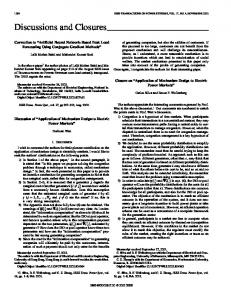
Fig. 1. System model: all relay nodes receive the signal broadcast by the SU’s transmitter during TS1. The relay node that has the best channel with S, considering both peak and average-power constraints, relays the information to SU’s receiver during TS2.
In detailing these contributions, the remainder of this article is organized as follows: Section II presents a brief description of the system model considered in this work. Section III derives some statistics for the end-to-end SNR, which will be used in Section IV to study the bit error rate (BER) for several modulations schemes, before concluding the article in Section V. II. S YSTEM M ODEL We consider a SU sharing the spectrum band with a primary user (PU). The former can transmit data using the available bandwidth 𝐵 of the spectrum as long as it meets interference criterion on the power received at the latter’s receiver. The SU’s transmitter, S, intends to send data to SU’s destination, D. Unfortunately, the channel between S and D experiences deep fading. In order to overcome this problem, a number 𝐿 of available terminals, denoted R1 , R2 , . . . , R𝐿 , act as relaying nodes between S and D (Fig. 1). The system functions using time-division multiple access (TDMA) and the relay nodes use amplify-and-forward technique. During the first time-slot (TS1), S broadcasts the signal which is received by all the relay nodes, such that: √ 𝑦𝑖 [𝑛] = ℎSR𝑖 [𝑛]𝑥S [𝑛] + 𝑧𝑖 [𝑛], 𝑖 = 1, 2, . . . , 𝐿, (1) √ where 𝑦𝑖 is the signal received at the 𝑖th relay node R𝑖 , ℎSR𝑖 is the channel gain between S and R𝑖 , 𝑛 is the time index, 𝑥S is the signal sent by the SU’s transmitter with average power 𝔼[∣𝑥∣2 ] (𝔼[.] is the expectation operator) and 𝑧𝑖 is the additive white Gaussian noise (AWGN) with variance 𝑁0 . As the SU is sharing the spectrum band with a PU, it has to maintain its power subject to certain constraints not to harm the PU’s communication process. Thus, we suppose that channel state information (CSI) are available for transmitting terminals through a band manager, and that during the first TS, S is subject to a joint constraint on both the peak- and the average-power received at the PU’s receiver denoted by P: { 𝒫(ℎSR𝑖 , ℎSP )ℎSP ≤ Qpeak , (2) 𝔼 [𝒫(ℎSR𝑖 , ℎSP )ℎSP ] ≤ Qavg , where 𝒫(ℎSR𝑖 , ℎSP ) is the transmit power of S considering
501
the channels ℎSR𝑖 and ℎSP and the expectation is over the joint distribution of ℎSR𝑖 and ℎSP . We suppose that the considered system uses partial relay selection (PRS). The selection of the “best relay” takes into account the secondary channels, ℎSR𝑖 , 𝑖 = 1, 2, . . . , 𝐿, as well as the secondary-to-primary channel, ℎSP . The selected “best relay” node R𝑏 will transmit the received data to the destination D, with a gain factor 𝐺 such that the average transmit power of the relay node is maintained the same as the average transmit power of the source. During the second time-slot (TS2), the best relay R𝑏 transmits the received information to the destination D. Relay R𝑏 will amplify the received signal by a certain gain-factor 𝐺 that will be dependent on the system constraints. The signal received at the destination can then be written as follows: √ √ √ (3) 𝑦D = 𝐺 ℎSR𝑏 ℎR𝑏 D 𝑥S + 𝐺 ℎR𝑏 D 𝑧𝑏 + 𝑧D , √ where ℎR𝑏 D is the channel gain between the best-relay node (R𝑏 ) and D, 𝑧D and 𝑧𝑏 are the AWGNs with the same variance 𝑁0 , where the index 𝑏 in 𝑧𝑏 is the same as the index of the selected best relay R𝑏 , and the time index [𝑛] is omitted as it is clear from the context. During TS2, the best relay R𝑏 ’s transmit power is subject to the joint constraint on the peakand average-received power at the PU’s receiver. Thus, we have: { 𝒫(ℎR𝑏 D , ℎR𝑏 P )ℎR𝑏 P ≤ Qpeak , (4) 𝔼 [𝒫(ℎR𝑏 D , ℎR𝑏 P )ℎR𝑏 P ] ≤ Qavg . All the mentioned channel gains are independent and identically distributed (i.i.d.) and follow the Rayleigh distribution with zero mean and variance 1/2.
III. S TATISTICS OF THE E ND - TO -E ND SNR A. Probability Density Function Considering that during TS1, the SU’s transmitter S is subject to the constraints defined in (2), the allocation of the SU’s transmit power, 𝒫(ℎSR𝑖 , ℎSP ), is formulated as [12]: ⎧ Qpeak ℎSP 𝛾1 , , ≤ ℎ ℎ 𝑁 SR𝑖 0𝐵 ⎨ 𝛾 SP 𝑁 𝐵 ℎSP 𝛾1 𝛾0 0 0 ≤ , − , ≤ 𝒫(ℎSR𝑖 , ℎSP ) = ℎ ℎ 𝑁 𝐵 ℎ 𝑁 SP SR 0 SR 0𝐵 𝑖 𝑖 ℎSP 𝛾0 ⎩ 0, , ≥ ℎSR𝑖 𝑁0 𝐵 (5) where the variables 𝛾0 and 𝛾1 are the cut-off values obtained such that the joint constraint on the peak and the average power is satisfied, and are related through: 𝛾1 = 𝛾0 − Qpeak,
(6)
with 𝛾0 defined as follows: 𝛾0 =
Qpeak ) − 𝑁0 𝐵. Qavg − Qpeak 1 − exp 𝑁0 𝐵 (
(7)
The power allocation in Eq. (5) allows us to find the probability density function (PDF) of the SNR 𝛾SR𝑖 of the first-hop
502
IEEE TRANSACTIONS ON WIRELESS COMMUNICATIONS, VOL. 11, NO. 2, FEBRUARY 2012
link S − R𝑖 where
=
Monte-Carlo Simulation
ℎSP 𝛾1 , ≤ ℎSR𝑖 𝑁0 𝐵 ℎSP 𝛾1 𝛾0 ≤ , ≤ 𝑁0 𝐵 ℎSR𝑖 𝑁0 𝐵 ℎSP 𝛾0 ≥ . ℎSR𝑖 𝑁0 𝐵
2
The distribution obtained in Eq. (8) is intended for any pair S − R𝑖 with the power constraints (2) at the PU’s receiver P. Next, we denote the SNR of the first hop by 𝛾SR = max 𝛾SR𝑖 1≤𝑖≤𝐿
[
]𝐿 𝐹𝛾SR (𝛾) = 𝐹𝛾SR𝑖 (𝛾) ,
(9)
where 𝐹𝑋 (.) is the cumulative distribution function (CDF) of the random variable 𝑋. The distributions of 𝛾SR and 𝛾RD are ⎧ 𝐿𝛾0 (𝑁0 𝐵)𝐿 𝛾 𝐿−1 , ⎨ (𝛾0 + 𝑁0 𝐵(𝛾 + 1))𝐿+1 𝐿Qpeak(𝑁0 𝐵)𝐿 𝛾 𝐿−1 𝑓𝛾SR (𝛾) = , (Qpeak + 𝑁0 𝐵𝛾)𝐿+1 ⎩ 0,
given as follows: 0≤𝛾≤
Qpeak , 𝛾1
Qpeak , 𝛾1 otherwise,
𝛾≥
0.5
0
0
0.5
γ
1
1.5
Fig. 2. Analytical results and Monte-Carlo simulations of the PDF of SNR for AF based relaying systems in Rayleigh fading environment under spectrumsharing constraints (𝐿 = 3, Qavg = −2.6 dB and Qpeak = 0 dB).
inverse of 𝛾end . Then, we have −1 −1 −1 𝛾end = 𝛾SR + 𝛾RD .
(13)
−1 𝛾end
is the simple sum of two random variables, some As statistics, such as the MGF, become simpler to derive as the result will be a simple product, rather then finding the distribution of the harmonic mean of 𝛾end . B. Moment Generating Function The MGF of a random variable 𝑋, which is the Laplace Transform of the PDF 𝑓𝑋 (.), is given by: ˆ +∞ ℳ𝑋 (𝑠) = 𝑒−𝑠𝑡 𝑓𝑋 (𝑡)𝑑𝑡. (14) 0
(10)
and 𝑓𝛾RD (𝛾) is the same as 𝑓𝛾RD (𝛾) but with 𝐿 = 1. Performing some mathematical manipulations, the PDFs of the inverse of 𝛾SR and 𝛾RD are obtained as: ⎧ 𝐿Qpeak(𝑁0 𝐵)𝐿 𝛾1 , 0≤𝛾≤ , 𝐿+1 Qpeak ⎨ (Qpeak 𝛾 + 𝑁0 𝐵) 𝑓𝛾 −1 (𝛾) = 𝛾1 𝐿𝛾0 (𝑁0 𝐵)𝐿 SR , 𝛾≥ , 𝐿+1 Q peak ((𝛾 + 𝑁0 𝐵)𝛾 + 𝑁0 𝐵) ⎩ 0, 0 otherwise, (11) and 𝑓𝛾 −1 (𝛾) is the same distribution as 𝑓𝛾 −1 (𝛾) with 𝐿 = 1. RD
1.5
1
Knowing that the distribution of the ratio of two Rayleigh random variables is the function 𝑥 �→ 1/(1 + 𝑥)2 [13] and using transformations of random variables, we obtain the following PDF: ⎧ 𝛾0 𝑁 0 𝐵 Qpeak , 2, 0 ≤ 𝛾 ≤ 𝛾1 ⎨ (𝛾0 + 𝑁0 𝐵(𝛾 + 1)) Qpeak 𝑁0 𝐵 Qpeak 𝑓𝛾SR𝑖 (𝛾) = 𝛾≥ , 2, 𝛾1 (Q + 𝑁 𝐵𝛾) peak 0 ⎩ 0, otherwise. (8)
so that:
Theoretical formula
2.5
SR
=
fγ −1 (γ)
𝛾SR𝑖
3
𝒫(ℎSR𝑖 , ℎSP )ℎSR𝑖 𝑁0 𝐵 ⎧ Q ℎSR𝑖 peak , 𝑁 𝐵 ℎ 0 ⎨ 𝛾 ℎ SP 0 SR𝑖 − 1, 𝑁 𝐵 ℎ 0 SP ⎩ 0,
SR
In Fig. 2, we plot the curve representing the theoretical expressions of 𝑓𝛾 −1 (𝛾) alongside with the Monte-Carlo simSR ulations and we see that there is a perfect match between simulation and theory. Now, we compute the statistical properties of the random variable 𝛾end defined by: 𝛾SR 𝛾RD 𝛾end = , (12) 𝛾SR + 𝛾RD which can be seen as a tight upper bound to the real end−1 be the to-end SNR and a more tractable expression. Let 𝛾end
For the purpose of derivation of closed-form expression, we have the following equality [14]: ( ) ˆ 𝑏𝑠 𝑒−𝑠𝑥 𝑠𝑝−1 𝑒 𝑎 𝑠𝑏 𝑑𝑥 = − Γ 1 − 𝑝, 𝑠𝑥 + , (15) (𝑎𝑥 + 𝑏)𝑝 𝑎𝑝 𝑎 where 𝑠, 𝑎, 𝑏 are positive real numbers, 𝑝 positive integer and Γ(., .) is the upper incomplete Gamma function defined by ´ +∞ Γ(𝑟, 𝑥) = 𝑥 𝑡𝑟−1 𝑒−𝑡 𝑑𝑡. As the PDF of 𝛾SR is a piecewise rational function, and using Eq. (15) into (14), we obtain the expression of the MGF −1 shown in Eq. (16). Following the same procedure, we of 𝛾SR obtain the expression of ℳ𝛾 −1 (𝑠) shown in Eq. (17). RD −1 Now, we can easily compute the MGF ℳ𝛾 −1 (𝑠) of 𝛾end end −1 −1 which will be the product of the MGFs of 𝛾SR and 𝛾RD . The MGF of 𝛾end is given by the following formula [15, Eq. (18)]: ˆ +∞ ( √ ) ( ) √ ℳ𝛾end (𝑠) = 1−2 𝑠 𝐽1 2𝛽 𝑠 ℳ𝛾 −1 𝛽 2 𝑑𝛽, (18) 0
end
where 𝐽𝛼 (𝑥) is the Bessel function of the first kind. As observed, the mixture of the functions involved in the integral makes it cumbersome to derive. Nevertheless, we can still use (18) to study the performance of our system based on the relationships that exist between symbol error rates and MGF [16].
BEN FREDJ and A¨ISSA: PERFORMANCE OF AMPLIFY-AND-FORWARD SYSTEMS WITH PARTIAL RELAY SELECTION UNDER SPECTRUM-SHARING . . .
ℳ𝛾 −1 (𝑠) SR
= +
)] [ ( ) ( 0 𝐵𝑠 𝐿(𝑁0 𝐵)𝐿 Q𝑁peak 𝑠𝑁0 𝐵 𝑠 𝐿 𝑒 𝑠 Γ −𝐿, (𝛾0 − Qpeak + 𝑁0 𝐵) − Γ −𝐿, Qpeak Qpeak Qpeak 𝐿 ( ( )) 𝑁0 𝐵𝑠 𝛾0 − Qpeak 𝐿𝛾0 (𝑁0 𝐵)𝐿 𝑁0 𝐵 𝛾0+𝑁 𝐵 𝐿 0 𝑒 𝑠 Γ −𝐿, 𝑠 + , (𝛾0 + 𝑁0 𝐵)𝐿+1 Qpeak 𝛾0 + 𝑁 0 𝐵
ℳ𝛾 −1 (𝑠) = RD
+
𝑃𝑏 (𝐸) = =
(16)
[ ( )] ) ( 0 𝐵𝑠 𝑁0 𝐵 Q𝑁peak 𝑠𝑁0 𝐵 𝑠 𝑒 𝑠 Γ −1, (𝛾0 − Qpeak + 𝑁0 𝐵) − Γ −1, Qpeak Qpeak Qpeak ( ( )) 𝑁0 𝐵𝑠 𝛾 𝛾0 𝑁 0 𝐵 − Q 𝑁0 𝐵 0 peak 𝛾0+𝑁 𝐵 0 𝑒 𝑠 Γ −1, 𝑠 + . (𝛾0 + 𝑁0 𝐵)2 Qpeak 𝛾0 + 𝑁 0 𝐵 √
(17)
√
] ) ( 2) 𝐴 𝐽1 2𝛽 1−2 ℳ𝛾 −1 𝛽 𝑑𝛽 𝑑𝜑 end sin2 𝜑 0 0 √ √ ( ) ˆ ˆ ( 2 ) 𝜋/2 1 𝐴 𝐴 2 +∞ − ℳ𝛾 −1 𝛽 𝐽1 2𝛽 𝑑𝜑 𝑑𝛽. end 2 𝜋 0 sin2 𝜑 sin2 𝜑 0 �� � � 1 𝜋
ˆ
𝜋/2
[
𝐴 sin2 𝜑
ˆ
+∞
503
(
(20)
ℐ(𝐴,𝛽)
IV. AVERAGE BER In this section, we study the evolution of the bit error rate (BER) of different simple modulation schemes for the partial relay selection system under the joint constraint on peak- and average-received powers.
where 𝐴 = 1 for BPSK and 𝐴 = 1/2 for BFSK. Plugging (18) in (19) leads to Eq. (20). The integral ℐ(𝐴, 𝛽) in (20) √ can be evaluated using the change of variable 𝑢 = 2𝛽 sin𝐴2 𝜑 . Next, considering the √ sin(2𝛽 𝐴) . formula [17, Eq. 2.12.4.15] leads to ℐ(𝐴, 𝛽) = 2𝛽 The BER can then be accurately tackled using the GaussLaguerre quadrature numerical integration: ( √ ) ˆ ( 2 ) sin 2𝛽 𝐴 2 +∞ 1 − 𝑑𝛽 ℳ𝛾 −1 𝛽 𝑃𝑏 (𝐸) = end 2 𝜋 0 2𝛽 𝑚 1 2∑ ≈ − 𝑤𝑖 𝑓 (𝐴, 𝑥𝑖 ) , (21) 2 𝜋 𝑖=1 where 𝑚 is the number of interpolation points, 𝑥𝑖 are the 𝑖th zeros of the Laguerre polynomial 𝐿𝑛 (𝑥), 𝑤𝑖 are the associated weights given by 𝑤𝑖 =
(𝑛!)2 𝑥𝑖 (𝑛 + 1)2 𝐿𝑛+1 (𝑥𝑖 )2
and 𝑓 (𝐴, 𝑥) = 𝑒𝑥 ℳ𝛾 −1 (𝑥2 ) end
( √ ) sin 2𝑥 𝐴 2𝑥
(22)
.
(23)
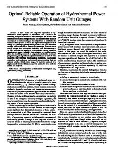
ρ=1 ρ = 1.1 ρ = 1.3
L=1
−1
10
Average BER
A. Coherent Binary Shift-Keying Signals The average BER of coherent binary signals, using the MGF-based form, is given by [16]: ( ) ˆ 𝐴 1 𝜋/2 𝑃𝑏 (𝐸) = ℳ𝛾end 𝑑𝜑, (19) 𝜋 0 sin2 𝜑
0
10
L=8 −2
10
−3
10
−5
0
5
10
15
20
Qavg [dB]
Fig. 3.
Coherent BPSK modulation BER versus Qavg .
B. Numerical Examples For the sake of simplicity, first we plot the BER results, obtained in the previous subsection, versus a single constraint, namely Qavg . The value of the peak power limit, Qpeak, can Q . This be deduced using the ratio 𝜌 defined as 𝜌 = Qpeak avg ratio indicates how important the impact of both constraints is. When 𝜌 tends towards 1, the contribution of Qavg vanishes and the system remains subject to a single constraint (Qpeak) while a value of 𝜌 greater than 1 creates more stringent constraints on the system. Fig. 3 depicts the average BER for coherent BPSK (𝐴 = 1) modulation schemes, versus the average power limit Qavg . The plot in Fig. 4 depicts the variation of the average BER as a function of the constraints’ limits Qpeak and Qavg . Our first remark is that, as expected, the BER decreases when the number of relay nodes 𝐿 increases; a fact that clearly
504
IEEE TRANSACTIONS ON WIRELESS COMMUNICATIONS, VOL. 11, NO. 2, FEBRUARY 2012
quadrature integration, the BER of coherent BPSK and BFSK modulation schemes. Alongside the benefits of the usage of multiple relay nodes, the numerical results showed that imposing more than a constraint on the system reduces the performance considerably. The provided results can be used as benchmark for designing transmissions approaches as to satisfy quality-of-service requirements in terms of BER in relay-based spectrum-sharing systems.
0
10
Average BER
−1
10
−2
10
ACKNOWLEDGMENT −3
10
−5
0
5
Qpeak [dB]
10
15
20
10
15
5
0
−5
Qavg [dB]
Fig. 4. Average BER for coherent BPSK when both limitations (Qavg and Qpeak ) vary, with 𝐿 = 10.
underlines the impact and the importance of multiple relays. Another observation, for low SNR, pertains to the fact that the BER gets slightly higher when the value of the ratio 𝜌 increases and the value Qavg is lower. This can be explained by a higher value of 𝜌 meaning a more important constraint on both, mean and peak, received powers at the PU’s receiver. For higher SNR, the average BER decreases faster for higher values of 𝜌. In fact, the constraint Qpeak is more relaxed for higher values of 𝜌, which means that the SU can transmit at higher power levels without causing harmful interferences to the PU and, thus, transmit data can be decoded easily and produces lower error rates. Also, it is important to mention that when 𝜌 = 1, the system behaves as if it is subject to a single constraint. In this case, the average BER will be lower than for the two previously mentioned values. In Fig. 4, we notice that half of the space is empty. This no-values region of the graph represents the region where the values of the average-power limit (Qavg ) is larger than the peak-power limit (Qpeak). This is comprehensible since the peak-power can never be lower than the average-power. For the feasible region, we note that the average BER decreases rapidly near the bisector plan Qpeak = Qavg , and that observations similar to the ones drawn for Fig. 3 apply. V. C ONCLUSION In this paper, we studied the performance of relaying systems with partial relay selection under joint constraint on the peak- and average-received powers at a third part’s receiver. We considered a SU sharing the available spectrum band with a PU as long as it meets the power interference requirements. We derived the PDFs of the SNR on the two hops and obtained the MGF of the end-to-end SNR in closedform. The latter was then used to evaluate, by means of
The first author would like to thank V. Asghari for fruitful discussion in the context of this work. R EFERENCES [1] Federal Communications Commission, “Spectrum policy task force report (ET Docket no. 02-135).” Available: http://hraunfoss.fcc.gov/ edocs public/attachmatch/DOC-228542A1.pdf, Nov. 2002. [2] J. Mitola and G. Q. J. Maguire, “Cognitive radio: making software radios more personal,” IEEE Personal Commun., vol. 6, no. 4, pp. 13–18, Aug. 1999. [3] M. Gastpar, “Gaussian multiple-access channels under received-power constraints,” in Proc. 2004 IEEE Info. Theory Workshop, pp. 452–457. [4] J. N. Laneman, D. N. C. Tse, and G. W. Wornell, “Cooperative diversity in wireless networks: efficient protocols and outage behavior,” IEEE Trans. Inf. Theory, vol. 50, no. 12, pp. 3062–3080, Dec. 2004. [5] E. Van Der Meulen, “Three-terminal communication channels,” Adv. Appl. Probab., vol. 3, pp. 120–154, Spring 1971. [6] A. Sendonaris, E. Erkip, and B. Aazhang, “User cooperation diversity— part I: system description,” IEEE Trans. Commun., vol. 51, no. 11, pp. 1927–1938, Nov. 2003. [7] L. Musavian and S. A¨ıssa, “Cross-layer analysis of cognitive radio relay networks under quality-of-service constraints,” in Proc. 2009 IEEE Veh. Technol. Conf. – Spring, vol. 1, pp. 1–5. [8] K. Ben Fredj, L. Musavian, and S. A¨ıssa, “Closed-form expressions for the capacity of spectrum-sharing constrained relaying systems,” in Proc. 2010 IEEE Inter. Conf. on Telecomm., pp. 476–480. [9] Y. Zhang, H.-H. Chen, and M. Guizani, editors, Cooperative Wireless Communications. CRC Press, 2009. [10] V. Asghari and S. A¨ıssa, “Cooperative relay communication performance under spectrum-sharing resource requirements,” in Proc. 2010 IEEE Inter. Conf. Commun., pp. 1–6. [11] I. Krikidis, J. Thompson, S. McLaughlin, and N. Goertz, “Amplifyand-forward with partial relay selection,” IEEE Commun. Lett., vol. 12, no. 4, pp. 235–237, Apr. 2008. [12] L. Musavian and S. A¨ıssa, “Capacity and power allocation for spectrumsharing communications in fading channels,” IEEE Trans. Wireless Commun., vol. 8, pp. 148–156, Jan. 2009. [13] A. Ghasemi and E. S. Sousa, “Capacity of fading channels under spectrum-sharing constraints,” IEEE Trans. Wireless Commun., vol. 6, no. 2, pp. 649–658, Feb. 2007. [14] “Wolfram Mathematica Online Integrator.” Available: http://integrals. wolfram.com/ [15] M. Di Renzo, F. Graziosi, and F. Santucci, “A unified framework for performance analysis of CSI-assisted cooperative communications over fading channels,” IEEE Trans. Commun., vol. 57, no. 9, pp. 2251–2257, Sep. 2009. [16] M. K. Simon and M.-S. Alouini, Digital Communications over Fading Channels: A Unified Approach to Performance Analysis, 1st edition. John Wiley and Sons, Inc., 2000. [17] A. P. Prudnikov, Y. A. Brychkov, and O. I. Marichev, Integrals and Series, Volume 2: Special Functions, Second Printing with corrections. Gordon and Breach Science Publishers, 1988.