provides an overview of object-oriented concepts and terms, and discusses the .... information systems modeling, analysis, and design (Iivari, 1991a, b; Balhn, ...
Computers md Engng Vol 26, No 2, pp 279-293,1994
Pergamon
ENTERPRISE SYSTEMS
Copyright~ 1994ElsevierScienceLid Pnnted m Great Britain All nghts reserved 0360-8352/94 $7 00 + 0 00
0360-8352(93)E0002-P
MODELING
FOR
ARCHITECTURES:
CIM
AN
INFORMATION
OBJECT-ORIENTED
APPROACH OJELANKI K. NGWENYAMAt and DELVIN A. GRANT2 LSchool of Business Admmlstratlon, Umverslty of Michigan, Ann Arbor, Michigan and "College of Business Administration, Rochester Institute of Technology, Rochester, New York, U.S A (Received for pubhcatwn 23 November 1993)
Abstract---Computer Integrated Manufactunng (CIM) reformation systems have become extremely important to the global competitiveness of most manufactunng firms. And although much has been written about CIM development and implementation many problems still plague practitioners For example, lack of integration, islands of automation, sub-opttmmation of resources, and the mabdtty to migrate to future technologyare a few types of problems Further, few methodologieshave beendeveloped that systematicallyaddress these issues In this paper, we outline an Object-Onentedapproach to modeling manufactunng enterprises The approach offersa procedureand techniques for definingCIM information systems architectures which could serve as bluepnnts for CIM development and tmplementauon in manufactunng enterprises
I INTRODUCTION As never before, computer integrated manufacturing information systems (CIMIS) architects and planners are faced with the pressures of plotting a course for CIMIS development and use, to meet the competitive and survival needs of world class manufacturing enterprises in the 1990s. They must understand the goals, objectives, and capabilities of their firms and develop strategies to attain these goals. This is no easy task, as the path to efficient and effective CIMIS is plagued with problems and often ends in failure. For several years, researchers and practitioners have been struggling to identify and document some of the major problems facing CIMIS development and implementation (see Table 1), but few integrated approaches have emerged for solving them. For the CIMIS architect and planner, the problems of charting a course for the manufacturing firm still remain. And although, progress has been made over the years, there are few methodologies to assist with the systematic planning and development of these complex systems (Flatau, 1988; Ciampa, 1988; Nalder and Robinson, 1987; Banerjee, 1986). This lack of methodologies has led to ad-hoc development practices that are associated with several of these organizational problems (Yeomans et a l , 1986; Ciampa, 1988; Gunn, 1987; Solberg, 1988; Flatau, 1988; Levvilis, 1985). Computer integrated manufacturing incorporates a wide range of information technologies, such as, electronic data processing (EDP), management information systems (MIS), decision support systems (DSS), expert systems (ES), computer-aided design (CAD), computer-aided manufacturing (CAM), computer-aided process planning (CAPP), flexible manufacturing systems (FMS), etc. Developing, implementing and operating manufacturing systems with these technologies, in the absence of appropriate planning and development methodologies, is an intractable problem. We believe that enterprise modeling methods and techniques developed to help solve orgamzational information management can provide assistance with many of the CIM problems cited above. In this paper, we present a case-study of the application of an Object-Oriented Enterprise Modeling (OOEM) approach to CIMIS planning and development. The approach focuses on systematically modeling the global information requirements needed to plan, design, and develop information systems for a CIM environment. The OOEM approach provides methods, technologies, a philosophy and procedure for identifying and representing the CIM processes, information flows, and data entities that are relevant to the goals and objectives of the manufacturing enterprise. We argue that this approach assists in narrowing the gap between planning and implementation, 279
280
OJELANKI K NGWEN'~AMA and DELVIN A GRA~T Table I CIM planning and mtegratmn problems (I) (2) (3) (4) (5) 16) (7) (8)
Lack of lntegrauon Methods and ~tpproaches CIM a~ an Emerging Fletd ,4d-Ho~ CIM Development Lack of Standards Lack of Understanding of CIM Variables Bottom-Up Approache~--Lack of Pre-Defined Architecture Island of n.utomat~on Paradigm Confusing and Narrow Defimtlons of CIM
and provides a conceptual view the information requirements, critical interfaces, and functional dependencies across the organization (Seifert and Settles, 1989; Kroenke, 1989). It also offers an alternative to ad-hoc CIMIS development, accommodates incremental development of systems, and supports the integration process. The rest of the paper is organized as follows: Section 2 discusses enterprise modeling (EM) and provides an overview of object-oriented concepts and terms, and discusses the advantages of applying these concepts to EM. Section 3 provides a case describing an application of the OOEM approach in a manufacturing firm. And finally, Section 4 concludes with a brief discussion of the lessons learned.
2 THE CIMIS PROBLEMSPACE The basic objective of CIM is to achieve enterprise-wide cost efficient and effective manufacture and distribution of the firm's products. A fundamental component of CIM is the information systems which support integration the core activities of different management levels, (strategtc, tactical and operattonal), and across business functions (purchasing, design, production, distribution) important to manufacturing. The successful manufacturing enterprise is a highly coordinated complex of Task, Technology, People, Communication, and Structure. Several studies have pointed out the importance of synergy among these aspects of the manufacturing enterprise (Leavitt, 1965; Galbrait, 1977; Yadav, 1983; Grant, 1991; Grant et al., 1992). Since the development and implementation of CIMIS is a change process that intervenes in the manufacturing enterprise, close attention must be given to each of these aspects. Figure l shows the conceptual relationships among the various organizational aspects and the levels of management in the manufacturing enterprise. In order to convey the complexity of the CIMIS problem space, we will briefly outline the organizational aspects that are important for the development and implementation of effective CIMIS. Task. From one perspective, organizations may be conceptualized as a complex of interrelated sets of tasks. These tasks may be performed by people, computers or machines working independently or in collaboration. Technology has become an essential component of modern manufacturing. Intense competitive pressures are forcing more manufacturers to adopt a wider
MOMT LEVELS
CIMIS ASPECTS
TASK
TECHNOLOGY
PEOPLE
Strategic
Tactical
Operational Ftg I CIMIS framework
COMM
STRUCTURE
Object-onented approach with CIMIS
281
variety of manufacturing technologies than ever before. These technologies often impact the organization structure, its task components, and human users. The efficient and effective integration and application of new technologies to the manufacturing process is vital to the survival of the firm. People. In as much as automation has advanced considerably, people remain vital to manufacturing. They are required to manage the manufactunng process, momtor and control computers and machines. Consequently, the human dimension should be carefully considered during the design of any human activity system. Peoples' skills, competence, and training are important parameters when deciding on the tasks to be performed, the technology to be used, the type of user interface to use, or the type of organizational structure to adopt. Communication. Two types of communication are important considerations for CIMIS development: technical and human. Technical communication concerns the ability of different types of technology to effectively communicate. Human communication concerns the ability of people to communicate with each other, computers, and machines. Technical communication is very important for CIMIS development because CIMIS attempts to integrate different types of IS, CIM technologies, and people. This integration is achieved by linking these different technologies via computer networks. Failure to address these human concerns has led to implementation problems which contribute to CIMIS failures. Structure. Structure is concerned with organizing how people, technology, and task complexes are arranged to achieve specific objectives of the enterprise. The type of technology (i.e tools, techniques, and processes), and the manufacturing and management philosophy of the firm are important parameters in determining organization structure. With regard to CIMIS, there is another important aspect of structure: the configuration and design of technology complexes. To effectively control and monitor an integrated CIMIS, levels of computer and machine control and monitoring are necessary. 2.1. The Enterprise Modehng Approach
Enterprise modeling provides methods, tools, techniques, and a philosophy for describing and analyzing relevant aspects of the business enterprise, and deriving a conceptual architecture upon which the development and implementation of CIMIS could be based. The architecture is a set of conceptual models representing key features of a business enterprise (such as functions, processes, activities, role responsibilities, information flows, data structures, etc.) that are relevant to global planning, analysis, specification, and development of IS. EM provides a top-down view of the enterprise's information requirements and a "road map" for guiding the development of integrated enterprise-wide information systems (Martin, 1983). There are several approaches to EM for information systems architecture development: BSP (IBM, 1984), BIAIT (Carlson, 1979), SASS (DeMarco, 1979), IE (MacDonald, 1986; Martin, 1989), SADT (Ross et al., 1977, McGowan and Marca, 1988), each with its own strengths and weaknesses. However, the approach that we are proposing is based on the Object-Oriented Paradigm which has simplicity as its greatest strength. Recently, researchers and practitioners have moved toward an object-oriented approach for information systems modeling, analysis, and design (Iivari, 1991a, b; Balhn, 1989; Bulman, 1989; Hoza et al., 1989; Ward, 1989). The primary motivation for this paradigm shift is the recognition that the object-oriented approach offers powerful but simple concepts for representing orgamzational reality and the system designer's ideas about the system of interest (Agha, 1985; Norman, 1991a, b; Iivari, 1991b). As Banerjee et al. (1987) see it, the "'objects", the basic concept of this approach, can be used "to represent anything from a simple number ... to a complex entity, such as an automobile or an insurance agency." 2.2. Object-oriented Modeling
Several approaches to object-oriented modeling of information systems have been suggested (Bailin, 1989; Bulman, 1989; Chen and Nunamaker, 1989; Hoza et al., 1989; Shlaer and Mellor,
282
ON t a,\KI K NGV*I-N~ a Me,
and DELVIN A GRANq
1988: Ward, 1989, Coad and Yourdon, 1990), each having individual strengths and weaknesses. Our approach, however, is informed by hvarl (1991a, b). who suggests a framework and a strategy for modeling Information systems which fit well within the basic objectives of enterprise modeling and architecture defimtion The framework Ident~fies three levels of abstraction in object-orienting modeling which are important to mtegrauon in CIM: (1) the orgamzanonal level defines the context of the information system and ~ts role in the organization; (2) the conceptual level defines the functional architecture of the lnformatlon system independent of technical and implementation considerations; and (3) the techmcal level defines the technological architecture of the reformation system upon which plans for ~ts mlplementatlon are based. Before we discuss the modeling strategy, we will outline the basra concepts to be used
2.2.1. ObJect-oriented concepLs The fundamental concept of the object-oriented paradigm is the object. Generally, objects may be characterized as active or passive. Active objects can operate on and transform passive objects The operations that transform passive objects are specific properties of active objects called methods. Methods are sets of procedures or rules for bringing about specified state changes in passive objects. Relevant examples of: (a) active objects are business processes and activities, computer hardware, and manufacturing tools; (b) passtve objects are data, manufacturing material etc.; and (c) methods are business and manufacturing procedures, design procedures, etc. Objects which share similar characteristics and enact or respond to similar methods are considered the same class. For example, we can represent all activities that have to do wlth the design of a specific product, say a compressor, as a class of compressor design objects; and at a higher level, all activities having to do with design in general as design objects. It should be clear that all compressor design objects share some similarities with the higher level design objects. In object-oriented language, we would say that these slmilariues are mhertted from the higher level design objects. Finally. acnve object~ commumcate with each other vm me.~sages These message~ could signal events, request operatmns to be performed, or report on operations completed
2.2.2 Archttecture definmon Enterprise modehng for CIMIS architecture defimtlon is a three phase process: (1) Requirements Definition, somenmes called business modeling; (2) Conceptual Design; and (3) Techmcal Design. In the requirements definition phase, the focus is on defining the role which the CIMIS must play in supporting the manufacturing enterprise. The Information it must provide and its orgamzatlonal context are defined via the modeling process in which the Global, Business, Information Flow, and Responsibility models for the functional area are developed. The Global Model defines the wider context, within which the organizational function to be supported by the CIMIS is situated. It defines the main interactions and information flows between the function of interest and other organizational functions. The Business Model is a representation of all the relevant aspects (processes, activities, information flows, roles, etc.) of the function of interest, and their relatmnships. The conceptual design phase consists of a set of activities concerned with defining the functional architecture of the CIMIS independent of technology considerations. The Data, Database, and Application models are developed in this phase. Essentially, the Conceptual design specifies the specific information (reports, screens, etc.) to be provided in support of the various work activities, the information processing procedures 0 e. Appllcatmn Model), and the database schema and definition of subject databases. The Technical design phase is concerned with identifying and analyzing different technological options for implementing the CIMIS. Computer and communications hardware and software options are identified and studied, and an appropriate cost effective, efficient, and reliable technical architecture is defined. In this phase, the designers must take into account existing hardware and interface requirements in order to optimize resource utihzation and throughput Three other important phases of activities must follow the CIMIS architecture definition if the gains of integration and system optimization are to accrue. They are: planning, systematic development and implementation. These are not the focus of this paper, but we will briefly discuss what was accomplished in these phases during the case study.
Object-onented approach with CIMIS
M°ssa °iowM 1 e'
Global Model
Business Model
f
Data Model
DB &
Port Model
283
--
Responstility Model ~---I
I
Data Comm Model
Fig 2 Overviewof CIMIS architecture models
2.2.3. The modehng procedure As stated above, eight conceptual models are used in derivmg the CIMIS architecture: Global Model, Business Model, Information Flow Model, Responsibility Model, Data Model, Apphcation Model, and Technology and Data Communication Model. The strategy for deriving the models is iterative and loop-linear (cf. Fig. 2). The iterations are important because the development of some models required Information derived from other models. The arrows in the center of each box indicate the primary flow for developing the seven models of the architecture. Because the development of a single model may be influenced by or dependent upon another, the arrows shown on the side of the boxes indicate the secondary flows. Therefore, for some models to be completely specified, both the primary and secondary flows are needed The procedure for derivmg a model ts as follows: (1) identify candidate objects, (2) classify them as actwe or passive, (3) define their characteristics, (4) define the methods they enact with or which operate on them, (5) define the messages that they send or receive, (6) construct the diagrams. In enterprise modehng, identifying and classifying objects of interest could be a difficult task. Figure 3 is a general framework for identifying and classifying objects in the problem domain. Although this framework is not comprehensive, it provides several examples that will assist inexperienced analysts, who might be modeling complex manufacturing enterprises, to quickly identify and classify relevant objects.
Levels of Modehn$ Orgamzattonal
Conceptual
Technical
OBJECT-ORIENTEDCONCEPTS Methods Objects Messages Business Process InformationFlows Business Procedures Business Activities Physical Flows Decision Making Procedures Organizational Roles Business Policy lnformaUonViews Information Handling Data Flows InformationProcessingProcedure Processes Communication Procedures Communication Processes Data Subject Databases InformationSystems Data Flows Applicauon Programs Database Structures Operating Procedures Hardware Systems Software Commumcauon System Fig 3. Conceptual framework for identifying objects
284
()JELANKI K NGWENYAMAand DELVINA GRANT CASE ILLUSTRATION
The domain of this case study is the Engineering Release Function (ERF) of a major manufacturing firm located in a northeastern state of the U.S.A. The E R F is responsible for pre-manufacturmg activities which focus on the processing, management, and distribution of engineering design informauon It is a specialized information resource management function which serves as the interface between engineering design and manufacturing The Engmeermg Release Function ts comprised of six departments (D1-D6), eight managers, and over 100 employees, most of whom are engineering and IS professionals. Each department ts responsible for a distinct set of information processing actwltles. D I assembles engineermg design data; and develops, generates, and distributes reports to other departments. D2 further processes the design data by adding more manufacturing process reformation and by instruction D3 creates process routings and their accompanying data. D4 and D5 collaborate on generating artwork NC data and manufacturing matermls requirements information The artwork mformatlon ~s a detailed description of the various features (holes, lands, etc ) that make up the "card", the image of the printed circuit boards which will be produced m the manufacturing stage. The mformatlon is produced by design engineers who work at various geographically dispersed Research and Development Labs The design data are transmitted over a wide-area commumcat~ons network to the Engineering Release Function. D6 ensures the manufacturabihty of the pre-manufacturmg product and ~s concerned w~th ~ssues of "'design for manufacturing'" The various types of information produced by the ERF are called pre-manufacturing products. These products are mputs to the Manufacturing Function which produce intermediary products (glass prototypes) and final products (printed circuit boards). The glass prototypes serve as templates for the manufacture of the printed circuit boards.
3. I. Project Team Structure and Process A multl-dlsclphned project team of 15-20 members from the 6 departments worked continuously on the EM project. The team consisted of IS specialists, pre-manufacturmg experts, 3 managers from the ERF, experts from design engineering and manufacturing, and external specialists (action researchers). The skill and experience of team members varied, the experience of application programmers ranged from 10 to 25 yr, while the experience of the expert users ranged from 15 to 25 yr. Many expert users had worked most of their careers in Release Function. The experience of lower level managers ranged from 7 to 16 yr Several had worked as application programmers in other business functions before joining the ERF. The primary responsibility of pre-manufacturlng and other experts was model development and validation. They worked closely with the IS professionals to ensure the models adequately represented the functions and activities within the umverse of discourse The responsibility of IS professionals was application design, development, and implementation. The primary responsibility of the analyst was to model the Release Function and to serve as an interface between programmers and users. It was the responsibility of the managers to administer the project, i.e. provide financial and other resources required by the project and report back to higher level management. The development team was divided into subgroups of 3-4 members to address specific problems Members who were most knowledgeable about particular aspects of the manufacturing process usually ended up on related projects Team responslbdmes ranged from requirements analys2s to Implementation. Special teams, called action teams, were responsible for conducting fact finding missions about obscure aspects of the business. Weekly meetings were held to allow action teams to report back to the project team and to management on the status of project activities.
3.2. Requirements Definmon Phase The action teams' fact finding missions were part of the requirements phase They were initiated from discussions that emerged from the development and analysis of the model of the ERF. A decision was made to model the ERF m order to aid the understanding of the problem domain
ObJect-oriented approach with CIMIS
285
and provide insight for problem resolution. One analyst commented, "it's amazing how much I have learned from the modeling exercise." He went on to say, "this level of understanding could not have been achieved in the absence of the model." One manager commented, "probably the most important product of the modeling exercise is the process (i.e. the learning and understanding that occurred among project team members), and not the product (i.e. the actual model)." The model served as a communication vehicle for debate and discourse among team members. By analyzing aspects of the model and with further analysis, the lower level requirements such as data object, mini specs, application programs, database design and so on were derived. The results of modeling the case-organization are now presented in summary. It is not practical to present in detail all the models we developed because this would require several pages and lead to information overload. Consequently, we present high level representations to give the reader a feel for the process. For example, in the case of the Object Business Model, we will present the first level of decomposition and omit the remaining six lower levels which are several pages long. 3.3. The Enterprise Models
In thts section, we illustrate an approach to Object-Oriented Enterprise Modeling by using the case description and discussion of the models. The order in which the models are presented is as follows: (1) Global Model, (2) Business Model, (3) Message Flow Model, (4) Responsibility Model, (5) Data Model, (6) Database Model, and (7) Technology & Data Communication Model. We do not intend to justify the need for such views but instead have accepted them as given because of their wide acceptability and use (cf. Carlson, 1979; IBM, 1984; Martin, 1984; MacDonald, 1986). 3.3.1. Global model
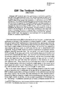
The Global Model is used to define the universe of discourse of our modeling exercise. It provides the foundation for integrating the enterprise and for developing the remaining enterprise models. The primary objective of the Global Model is to capture, at the highest level of abstraction, the interactions among the organization systems and/or subsystems of interests. The model shows the primary information links (i.e. messages) upon which the systems are to be integrated. The messages represent the natural flow of information among the various systems. Developing the Global Model required the definition of major operating systems, also considered objects, that are embedded in the enterprise without regard to artificial boundaries such as departments, and defining the primary messages that are passed between them. Figure 4, below, is a representation of the Global Model of our host company. It describes the organizational context of the ERF, and its Interactions with other organizational functions within the manufacturing enterprise. As can be seen, the Engineering Release function receives its primary inputs (product descriptions) from the Product Design and Development function, and generates outputs to various functions within manufacturing (e.g. Order Release, MRP, and so on). 3.3.2. Business model
The Business Model is derived by decomposing each subsystem (i.e. object) into its set of related activities/processes (i.e. lower level objects). The Business Model is a representation of the set of tasks/activities that are performed to support some aspect of the business. It documents the minimum set of activities or tasks that must be performed if the organization is to function efficiently. Moreover, it serves to identify information flows (messages) that are necessary to support organizational tasks. A model of the existing system is developed and analyzed to identify missing activities (information/message flows) to add process control mechanisms or to eliminate redundant and unnecessary activities. This analysis serves to eliminate, from the Business Model, the complexities that have been built into the business over the years (Clark, 1989). The objective is to simplify the Business Model and increase its efficiency before attempting automation. Figure 5, the Business Model, is a high level description of the six major processes within the ERF and the primary informational interactions. It must be stated that this is the highest level of abstraction of the Business Model. Each process represented in the Business Model is further decomposed at lower levels to identify and represent its individual tasks and their information needs.
286
OJELANKIK NGWENYAMA and DELVINA GRANT
tpr & cpp
customerneeds
* shipments
[development]
~network
F-~ order ""~l °rder shlpmg ~ ' ~ control processingI ~ m v
~
I--"mfg leOW~:x~rders
status
~l
I mt°erdrpelantI
I purchasmgI
shippmg/ recewmg
I lnterplant orders
I purchase orders
engineering release
I order ~ scheduling
order release
I jout: on supplies
supphes
I
NCdata ] generation I
~- [mnfgstarting work I ~ ' ~
momtonng
II
repair
[monitoring
] starting
preventive/
/
wtp _[ IJ ] tru'put ] scrap yield I status -----~ data store I-" summaries & rework end userquenes& mgmt reporting Fig 4 Global model of the manufacturmgenterprises
3.3.3. Message flow model
The Message Flow Model describes information flows (messages) that are received or generated by activities or functtons at different levels of abstraction. The natural starting point for constructing the model is the Business Model. The interactions among the business activities are documented in detail, describing the content of information exchange and timing. Figure 6 is a summary of the primary information flows among the processes depicted in the Business Model above. 3.3.4. Responsibility model
The Responsibility Model documents the role responsibility for informatton processing at various levels of the organization. This model makes explicit the organizational role relationship
Objeet-onented approach with CIMIS
287
and control of information. It documents which objects (individuals or machines) have access or control over which messages. Figure 7 is a Responsibility Model showing a small set of activities of the Engineering Release Function. On the left side of the figure the role is identified, and on the right the information that is either used or generated is identified. The legend and an example below Fig. 7 illustrates how the data on the right of the figure should be interpreted. 3.4. Conceptual Design Conceptual design is the second phase of the EM process following requirements definition. It is the process of constructing the detail architecture models (Data Model, Database and Application Models, and the Data Communication Model) that are independent of implementation details, such as target communications network and database management systems. The primary input to conceptual design is the information requirements derived from the Business Model.
3.4. I. Data model The Data Model is a description of the data which are used and generated by the tasks and their relationships. The data model is used to derive database schema during database design. To develop
C 11 PRODA.e._lkI 12 PROD B ~.~l CI
PROD/DOC/INFOLIST
GEN ENGINEERING DATA & CREATE DOCUMENTS
Ol engineering I I L,'Panel features data for NC generation I I documents
~
card profile&
- manfgguidelines,reqs. & constraints 0
CREATE PANELLAYOUT
e. .o
panel layout ~
u
panel size constraints& optimization heuristics /
"-I ADD DESIGN FEATURES ~-
~..~
descnptlon of panel layout with deslsn features
CREATE GLASSNC DATA
1
GENERATE G/MASTER DATA
~ BOM info. 13 '~ 14
engineeringspecs.
CREATE GLASSROUTING
glass routing
to shop floor
process fine lnfo.
Fig. 5 Businessmodel of the engmeenngrelease function CAIE 26/2--F
P~ 02
artwork info. describing ~ 03 •[G/master N
I ,--!
NC data to manfg
tO4
288
OJELANKIK NGWENYAMAand OELVINA GR~.NT INPUT Product descrlptmns single mmge Tech. data
ENGINEERING RELEASE FUNCTION Design Process Design Process
Prod description unit image Process hne lnfo
Product Process
Machine avmlabthty
Routmg Process
Process hne mfo. Cost mfo Artwork descnptmn of product i Restructured englneenngdata
Artwork Process
OUTPUTS Product design data Restructured engineering data Panel layout mfo Artwork descriptions Artwork mstrucuons Routing info to shop floor
Routing Process Routing Process Routln$ Process NC Process
NC data to manufactunng
Ftg 60blect message flow model reformation flows among processes of the engineering release funcuon
the data model, the a n a l y s t in c o l l a b o r a t i o n with users, focused o n the Business Model acUvlttes to tdentify the necessary s u p p o r t i n g data objects. Thts exercise is aided by d o c u m e n t s such as memos, forms, a n d reports used by individuals who p e r f o r m the activtttes. A hst of object classes is compiled a n d analyzed to remove r e d u n d a n c i e s a n d resolve n a m i n g problems. D e p e n d i n g u p o n the n u m b e r o f objects, clustering m a y be necessary to arrive at logical sets o f objects (Le object classes a n d subclasses) which m a y be represented in several databases. The final step ~s to model each subclass o f objects using a n object-oriented d a t a model. In developmg the D a t a Model, the concept of inheritance can be utilized. F o r example, the root of the data model can exhlbtt b e h a w o r s c o m m o n to a n object class or subclass while lower level objects exhibit more spectalized behaviors. F~gure 8 shows the bastc data a n d the relationships that must be m a n a g e d m s u p p o r t
Role
Information Flows
Operator Who Generates Engmeenng Data
Description of Product A (u) A 1[ 1]I 1 Descnption of Product B (u) A I [ I]I 1 Tech Data (u) Al[I]I2 Panel Layout with Design Features Description (u) A l[l]13 Engmeenng Data Passed to NC Type Database (c) A 1[ I ]O I Information Needed to Decide Type of Docs to Gen (u) Al[l]O3 = I112] Engmeenng Data Req. to Create Docs (u) A 1[ 1]02 = I 1[3] Decision Concerning Type of Docs to be Gen (c) A I[2]OI
Operator Who Generates Documents:
Engmeenng Data Req. to Create Docs (u) A 1[3]I 1 Decision Concerning Type of Docs to be Gen (u) A 1[3]I2 Created Documents (c) AI[3]OI = Al[4]ll
i Operator Responstble For Venfying and Distributing Documents Panel Designer:
Created Docs. (u) A l [41I1 Card Profile & Panel Features Docs (c) AI[4]OI Card Design Features Document (c) A 1[4]02 lnfo About Panel Features (u) A2[I]II & A212]I2 Card Overall Dimensions (u) A213]12 Card Panel Layout lnformauon (u) A214]Il Acceptable Panel Layout (c) A214]02 List of Panel Sizes (u) A212]C1 Manufacturing Constraints (U) A212]C1 Manufactunng Guidelines for Panel Layout (u) A213]C1
F~g 7. Responslbdtty model for some engineering release actlvmes Legend name of mfo +(use or create) + node# + [process#] + input# or output# Example tech data + (u)+ AI[I] + (II) Note the Al, [I], and (ll) refer to the Business Model
ObJect-orientedapproach with CIMIS manfgingprocess] request / is made~ I process ~ carries out