molecules Article
Photocatalytic Activities of Copper Doped Cadmium Sulfide Microspheres Prepared by a Facile Ultrasonic Spray-Pyrolysis Method Jinzhan Su *, Tao Zhang, Yufeng Li, Yubin Chen and Maochang Liu International Research Center for Renewable Energy, State Key Laboratory of Multiphase Flow in Power Engineering, Xi’an Jiaotong University, No. 28, Xianning West Road, Xi’an 710049, Shaanxi, China;
[email protected] (T.Z.);
[email protected] (Y.L.);
[email protected] (Y.C.);
[email protected] (M.L.) * Correspondence:
[email protected]; Tel.: +86-29-8266-8296 Academic Editor: Nick Serpone Received: 9 May 2016; Accepted: 2 June 2016; Published: 15 June 2016
Abstract: Ultrasonic spray pyrolysis is a superior method for preparing and synthesizing spherical particles of metal oxide or sulfide semiconductors. Cadmium sulfide (CdS) photocatalysts with different sizes and doped-CdS with different dopants and doping levels have been synthesized to study their properties of photocatalytic hydrogen production from water. The CdS photocatalysts were characterized with scanning electron microscopy (SEM), X-ray fluorescence-spectrometry (XRF), UV-Vis absorption spectra and X-ray diffraction (XRD) to study their morphological and optical properties. The sizes of the prepared CdS particles were found to be proportional to the concentration of the metal nitrates in the solution. The CdS photocatalyst with smaller size showed a better photocatalytic activity. In addition, Cu doped CdS were also deposited and their photocatalytic activities were also investigated. Decreased bandgaps of CdS synthesized with this method were found and could be due to high density surface defects originated from Cd vacancies. Incorporating the Cu elements increased the bandgap by taking the position of Cd vacancies and reducing the surface defect states. The optimal Cu-doped level was found to be 0.5 mol % toward hydrogen evolution from aqueous media in the presence of sacrificial electron donors (Na2 S and Na2 SO3 ) at a pH of 13.2. This study demonstrated that ultrasonic spray pyrolysis is a feasible approach for large-scale photocatalyst synthesis and corresponding doping modification. Keywords: CdS; doping; photocatalytic; spray pyrolysis
1. Introduction Photocatalytic water splitting has continuously been a hot academic topic since Fujishima and Honda1 s work in hydrogen production from water using a TiO2 electrode [1]. Over the past decades, metal sulfides [2] and chalcogenides [3] have attracted broad interest from scientists engaged in photocatalysis. Of those compounds, cadmium sulfide (CdS) is an attractive semiconductor photocatalyst under continuous research due to its optimal band gap and suitable position of the conduction band and valence band edge [4–6]. Various CdS nanostructures or combinations were applied as photocatalysts for solar hydrogen production [7–9]. One drawback of this material is the photocorrosion by the photogenerated holes from the valence band of the CdS during the photocatalytic reaction in aqueous solution. In order to overcome the inherent disadvantages of CdS photocatalyst for hydrogen production, hybrid composites or solid solution based on CdS have been explored to improve the separation of photogenerated holes and electrons as well as their stabilities, and thus promote the overall photocatalytic activity [10–15]. Some photocatalysts with unique structure show promising efficiency and potential for large scale photocatalytic water splitting application [16]. Many novel Molecules 2016, 21, 735; doi:10.3390/molecules21060735
www.mdpi.com/journal/molecules
Molecules 2016, 21, 735
2 of 10
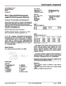
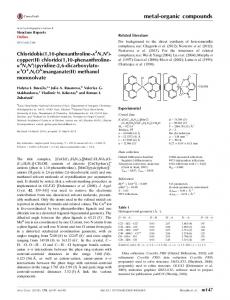
methods have been applied for preparing and synthesizing CdS particles. Bao et al. [17] prepared nanoporous CdS nanostructrues by method of self-templanted synthesis, having a high hydrogen yield under visible light irradiation. Many other techniques such as hydrothermal method [18], thermal evaporation [19], biogenic synthesis [20], chemical bath deposition [21] were applied to prepare CdS nanostructures. It is reported that spray pyrolysis is an efficient way to prepare sulfides or oxides microspheric powder or films [22–24]. With this method, one can synthesize micro-particles of different sizes which range from submicrometers to micrometers by controlling the various concentrations of metal nitrates in their starting aqueous solution. Kikuo Okuyama et al. [22] prepared CdS fine particles with different particle sizes by an Ultrasonic spray-pyrolysis method. In Kikuo’s work, ZnS and CdS fine particles with different particle sizes have been prepared and the effects of temperature profile in the reactor furnace and concentration of the metal nitrates in the solution on the properties of prepared particles were also investigated. Doping is a viable approach for modulating electrical, optical or photocatalytical properties of photocatalyst [25]. It can be used to reduce the band gap of photocatalyst by forming intermediate bands [26] or improve the chemical stability by injecting the holes into the formed acceptor energy level and reduce their activity on photocorrosion. [27] In our previous report, Cu doped CdS thin films were deposited by ultrasonic spray pyrolysis (USP). The non-uniform distribution of Cu atoms in the host CdS films formed disordered local p-n junctions which facilitate charge separation [28]. In addition, it has been reported that the USP method is a simple and cost-effective technique to prepare photocatalyst with different doping levels. A. Rmili et al. [29] prepared the undoped and Ni-doped CdS thin films with various doping levels by spray pyrolysis technique. The spray pyrolysis technique is considered as one of the most promising techniques for producing large scale inexpensive CdS catalyst for massive solar hydrogen application. In this study, we synthesized the spherical CdS nanoparticles with different sizes profile and Cu doped CdS photocatalyst with different doping levels by ultrasonic spray pyrolysis. The dopants were added directly into the precursor for spray pyrolysis. The temperature in the tube-furnace was kept constant while the concentrations of metal nitrates, dopants and in the precursors containing Cd(NO3 )2 ¨ 4H2 O and SC(NH2 )2 were adjusted to change the particle size or doping level. The UV-Vis absorption spectrum, crystalline phase, fluorescence properties and photocatalystic activities of CdS or doped CdS photocatalysts were tested to investigate the effect of particle-sizes, dopant and doping level on their structural, optical and photocatalytic properties. 2. Results and Discussion 2.1. Morphological, Optical and Structural Properties of Undoped CdS Particles Figure 1 shows SEM images of spherical CdS particles obtained from different starting-solution concentrations at a constant pyrolysis temperature of 500 ˝ C. It was found that the particle sizes increase with increasing starting-solution concentration and the surface of CdS particles is rather rough because it originates from aggregation of primary particles [22]. In addition, it is observed that the CdS particles prepared with same concentration possess different sizes. This can be due to the collision between precursor droplets and creating droplets with different sizes during the deposition. However, the average particle size can be controlled by changing the concentration of the starting solution. The TEM images shown in Figure 1d confirmed the rough surface of CdS particles and ununiformed sizes of obtained CdS particles. Figure 2 shows the UV-Vis absorption spectra of prepared CdS nanoparticles with different starting-solution concentrations. The direct band gap (Eg ) can be determined using the Tauc relation given by [30]: pαhνq2 “ A ˆ phν ´ Eg q (1) where A is a constant, α is the absorption coefficient, and hν is the photon energy. The intersection with the x-axis of the plot of (αhν)2 versus hν corresponds to the optical gap Eg . The bandgaps of CdS
Molecules 2016, 21, 735
3 of 10
2.31 eV, 2.28 eV and 2.25 eV, respectively. These values are all smaller than the typical value for bulk 21, 735 3 of 10 CdS Molecules sample2016, (about 2.4 eV) and this red shift increased with increasing starting-solution concentration. The red shift could originate from the surface defects of the CdS nanoparticles [31], that is because the defect states could underestimate bandgap energy samples containing such defects. to be with precursor solution concentrations of 0.1 mol/L, 0.5for mol/L and 1.0 mol/L were determined Molecules 2016, 21, 735
3 of 10
2.31 eV, 2.28 eV and 2.25 eV, respectively. These values are all smaller than the typical value for bulk 2.31 eV, 2.28 eV and 2.25 eV,this respectively. valueswith are all smaller than the typical value for bulk CdS sample (about 2.4 eV) and red shiftThese increased increasing starting-solution concentration. CdS sample (about 2.4 eV) and this red shift increased with increasing starting-solution concentration. The red shift could originate from the surface defects of the CdS nanoparticles [31], that is because the The red shift could originate from the surface defects of the CdS nanoparticles [31], that is because defect states could underestimate bandgap energy for samples containing such defects. the defect states could underestimate bandgap energy for samples containing such defects.
(a)
(c)
(b) (a)
(b)
(c)
(d)
(d)
Figure 1. Scanning electron microscope images of CdS particles obtained from different startingFigure solution 1. Scanning electron microscope images of CdSandparticles obtained from different concentrations: (a) 0.1 mol/L; (b) 0.5 mol/L; 1.0 mol/L TEM imagesfrom of CdSdifferent particles startingFigure 1. Scanning electron microscope images of (c)CdS particles(d)obtained starting-solution concentrations: (a) 0.1 mol/L; (b) 0.5 mol/L; (c) 1.0 mol/L and (d) TEM images with concentrations of 1.0 mol/L.
solution concentrations: (a) 0.1 mol/L; (b) 0.5 mol/L; (c) 1.0 mol/L and (d) TEM images of CdS particles of CdS particles with concentrations of 1.0 mol/L. with concentrations of 1.0 mol/L.
(a)
(b)
Figure 2. The UV-Vis absorption spectra (a) and corresponding Tauc plot (b) of CdS with different starting-solution concentrations.
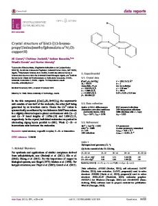
Figure 3a shows XRD patterns of the CdS particles obtained from different solution concentrations (a) (b) at a constant temperature. No effect of precursor concentration on the structural phase was found. The hexagonal phase ofabsorption CdS particlesspectra with good crystallinity were obtained for all precursor Figure 2. The UV-Vis (a) and corresponding Tauc plot (b) CdS of concentrations. CdS with different Figure 2. The UV-Vis (a)different and corresponding Tauc plot (b) with different The capabilities of H2 absorption evolution ofspectra CdS with precursor concentrations areof shown in Figure 3b. starting-solution concentrations. starting-solution concentrations. The results indicate that the activity of H2 evolution and the stability are clearly improved with the decrease of the CdS particle size, which could be due to a higher surface area in smaller CdS particles Figure 3a shows XRD patterns ofofthe CdS obtained from different solution concentrations synthesized by a XRD lower concentration precursor than that obtained of larger ones. Figure 3a shows patterns the CdS particles particles from different solution concentrations
at a constant temperature. No No effect of precursor concentration onon the structural at a constant temperature. effect of precursor concentration the structuralphase phasewas wasfound. found. The hexagonal phase of phase CdS particles goodwith crystallinity were obtained all precursor The hexagonal of CdS with particles good crystallinity werefor obtained for allconcentrations. precursor The capabilities of H2The evolution of CdS with different precursor concentrations are shown in Figure 3b. concentrations. capabilities of H evolution of CdS with different precursor concentrations 2 are shown in Figure 3b. The results indicate that the activity of H evolution and the stability are the The results indicate that the activity of H2 evolution and the stability are clearly improved with 2 clearly with thesize, decrease of could the CdS which could be due a higher surface decrease of improved the CdS particle which beparticle due to size, a higher surface area intosmaller CdS particles area in smaller CdS particles synthesized by a lower concentration precursor than that of larger ones. synthesized by a lower concentration precursor than that of larger ones.
Molecules 2016, 21, 735
4 of 10
Molecules 2016, 21, 735
4 of 10
(a)
(b)
Figure3. 3.The Thecrystal crystalstructure structure and and performance. performance. (a) and (b)(b) hydrogen Figure (a)X-ray X-raydiffraction diffractionpatterns patterns and hydrogen evolution rate of CdS particles prepared at different starting-solution concentrations: 0.1 mol/L, evolution rate of CdS particles prepared at different starting-solution concentrations: 0.1 mol/L, 0.5 mol/L and 1.0 mol/L. 0.5 mol/L and 1.0 mol/L.
2.2. Morphological, Optical and Structural Properties of Cu Doped CdS Particles 2.2. Morphological, Optical and Structural Properties of Cu Doped CdS Particles To investigate the doping effect on the photocatalytic activity of CdS particles, we doped CdS To investigate the doping effect on the photocatalytic activity of CdS particles, we doped CdS with Cu at doping levels of 0.2 mol %, 0.5 mol % and 1.0 mol %. to adjust its structural, electrical, and with Cu at doping levels of 0.2 mol %, 0.5 mol % and 1.0 mol %. to adjust its structural, electrical, and optical properties. In order to facilitate the identification of Cd, Cu and S in the Cu-doped CdS samples, optical properties. In order to facilitate the identification of Cd, Cu and S in the Cu-doped CdS samples, X-ray fluorescence-spectrometry of 1.0% Cu-doped CdS was studied. To avoid the misleading that may X-ray fluorescence-spectrometry 1.0% Cu-doped was To avoidsample the misleading that may result from the detection limit ofofthe method, only CdS results forstudied. 1.0% Cu-doped was presented. result from the detection limit of the method, only results for 1.0% Cu-doped sample was presented. Table 1 shows XRF data of 1.0% Cu-doped CdS particles. From Table 1, one can see that the ratio of Table 1 shows data ofmeans 1.0% Cu-doped CdS precise particles. 1, one can see thatby theprecursor ratio of Cu Cu to Cd is XRF 0.01 which that it is very to From controlTable element doping level to composite Cd is 0.01 which means it is very precise to control element doping levelthat by precursor composite adjustment in that ultrasonic spray pyrolysis method. We can also find there should be a adjustment in ultrasonic spray(V pyrolysis We of can findhigher that there a high high density of Cd vacancy Cd) as themethod. mol ration S also is much thanshould that ofbe Cd. Sincedensity the of formation Cd vacancy (V ) as the mol ration of S is much higher than that of Cd. Since the formation energies energies Cd of Cu substitutional defect (CuCd) is smaller than Cd vacancy (VCd), presence of of Cu Cuin substitutional (CutoCdeliminate ) is smaller Cd vacancy the sample is defect expected the than VCd defect [32]. (VCd ), presence of Cu in the sample is expected to eliminate the VCd defect [32]. Table 1. X-ray fluorescence-spectrometry (XRF) analysis result of 1.0% Cu-doped CdS. Table 1. X-ray fluorescence-spectrometry (XRF) analysis result of 1.0% Cu-doped CdS.
Title Intensity (KCps) wt % mol %
Cu 11.0 Title 0.385 Intensity (KCps) 0.335 wt % mol %
Cd 346.3 Cu Cd 66.7 11.0 346.3 32.96566.7 0.385
S 223.3 S O 27.5 223.3 0.1 27.5 47.74 5.46
0.335
47.74
32.965
O 0.1 5.46 18.957
18.957
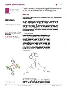
Figure 4a shows XRD patterns of CdS paticles of different Cu-dopants levels with ratio of Cu to Cd: 0.0%, 0.2%, 0.5% and 1.0%. No change of XRD pattern was observed between CdS particles with different Figure 4a shows XRD patterns of CdS paticles of different Cu-dopants levels with ratio of Cu Cu-doping levels, This could be due to the small doping level that does not affect the hexagonal phase of to Cd: 0.0%, 0.2%, 0.5% and 1.0%. No change of XRD pattern was observed between CdS particles the CdS particles. The average crystalline sizes of Cu doped samples were estimated from the XRD with different Cu-doping levels, This could be due to the small doping level that does not affect patterns using the Scherrer equation [33]. The crystallite sizes calculated using the Scherrer equations are the hexagonal phase of the CdS particles. The average crystalline sizes of Cu doped samples were 111.5 nm, 77.4 nm, 77.0 nm and 76.8 nm for 0%, 0.2%, 0.5% and 1% doped samples, respectively. The estimated from the XRD patterns using the Scherrer equation [33]. The crystallite sizes calculated decrease of crystallite size could result from the presence of Cu in the doped samples which causes using the Scherrer equations arenanoparticles 111.5 nm, 77.4 nm, 77.0 nm and process 76.8 nm[34]. for To 0%,further 0.2%, investigate 0.5% and 1% restriction to the growth of CdS during the pyrolysis doped samples, respectively. The decrease of crystallite size could result from the presence Cu in valence state of Cu, XPS is carried out and the XPS profile of Cu 2p is presented in Figure 4b. The Cuof2p 1/2 the(949.6 doped causes thethe growth of CdS nanoparticles during the of pyrolysis 2+ [35]. The SEM eV)samples and Cu which 2p3/2 (929.6 eV)restriction lines verifytothat Cu exists as Cu images CdS process [34]. To further investigate valence state of Cu, XPS is carried out and the XPS profile of Cu particles of different Cu-dopants levels were also obtained to check the doping influence on the 2pmorphology is presentedand in Figure 4b. The Cu 2p (949.6 eV) and Cu 2p (929.6 eV) lines verify that the size of CdS particles. It was clearly shown in Figure 1/2 3/2 5 that the doping increased theCu 2+ exists as Cucompared [35]. The images of CdS different levels were showed also obtained porosity to SEM the undoped one as particles shown inofFigure 1b.Cu-dopants However, the porosity no to significant check the doping on doping the morphology of CdS particles. was clearly shown changes influence at different level and and the size average particle sizes Itscarcely changed for in different samples. Figure 5 that the doping increased the porosity compared to the undoped one as shown in Figure 1b. Thethe influence of showed Cu doping on the bandchanges gaps ofatCdS particles were level investigated the UV-Vis However, porosity no significant different doping and theby average particle absorption Figure 6 shows the UV-Vis absorption spectra of Cu-doped prepared by ultrasonic sizes scarcelyspectra. changed for different samples. spray at of various molar ratio of band Cu/Cd.gaps It can seen that all were the samples show a by visible-light Thepyrolysis influence Cu doping on the ofbe CdS particles investigated the UV-Vis
absorption spectra. Figure 6 shows the UV-Vis absorption spectra of Cu-doped prepared by ultrasonic spray pyrolysis at various molar ratio of Cu/Cd. It can be seen that all the samples show a visible-light absorption region from 500 nm to 560 nm, and slight blue shifts of the absorption edge of Cu-doped
Molecules Molecules 2016, 2016, 21, 21, 735 735 Molecules 2016, 21, 735
55 of of 10 10 5 of 10
absorption region from 500 nm to 560 nm, and slight blue shifts of the absorption edge of Cu-doped CdS absorption region from 500 nmcomparing to 560tonm, and slight blue shifts the absorption edge of Cu-doped CdS particles were observed comparing pure CdS particles. Theofband gaps gaps of pure CdS particles and CdS particles were observed to pure CdS particles. The band of pure CdS particles particles were observed comparing pure CdS band pure particles and Cu-doped CdS can be can calculated by thetoTauc plots asparticles. shown Figure 6b. ItFigure wasoffound the band gaps and Cu-doped CdS be calculated by the Tauc plots in asThe shown ingaps 6b. that ItCdS was found that Cu-doped CdSincreased candoped be calculated by the plots as shown in Figure 6b. It wassulfide found that the band gaps of doped with CuTauc doping concentration. Since copper possesses asulfide lower the band CdS gaps of CdShigher increased with higher Cu doping concentration. Since copper of doped CdS increased with higher Cu to doping copper possesses a lower band gap compared to CdS, possibility of CuSconcentration. formation canSince be out.sulfide The Cucan element did not possesses a lower band gapany compared CdS, any possibility ofruled CuS formation be ruled out. bandCu gap compared toof CdS, possibility of levels; CuS can be cause ruledlevels; out.band The Cu element not decrease the banddid gaps CdSany by forming new however, it can the gap increase which The element not decrease the band gaps of formation CdS by forming new however, it candid cause decrease the gaps of by forming levels; however, it can the band gap increase could originate from quantum effects of the new decreasing of crystallite size after Cu doping [36,37]. high the band gapband increase which originate from quantum effects ofcause the decreasing of size Molecules 2016, 21,CdS 735 could 5crystallite of 10 Thewhich couldCu originate effects of thedefect decreasing ofnanoparticles crystallite sizesynthesized after Cu doping [36,37]. high density defect offrom CdSquantum nanoparticles synthesized byCdS pyrolysis method narrowed the gapsThe of CdS after doping [36,37]. The high density of byband pyrolysis method absorption region from 500 nm to 560 nm, and slight blue shifts of the absorption edge of Cu-doped CdS densityin defect of 2) CdS nanoparticles synthesized pyrolysis method narrowed the band gaps CdS (shown Figure by creating states in theby band gap,The while Cu doping increased the bandofgaps narrowed the band gaps CdSdefect (shown in toFigure 2) by creating defect the band gap, particles wereofobserved comparing pure CdS particles. band gapsstates of pureinCdS particles and while Cu (shown in Figure 2) byband creating defect states in the band gap, while Cu doping increased the band gaps of CdS particles which shift the band gaps towards the typical forback bulk CdS sample. doping increased the of CdS which shift the 6b. band gaps towards the typical Cu-doped CdS cangaps be calculated byparticles theback Tauc plots as shown in Figure Itvalue was found that the band gaps doped CdS increased with higher doping concentration. Since copper sulfide a lower of CdSfor particles which shift the band gapsCuback towards the typical value forpossesses bulk CdS sample. value bulk of CdS sample. band gap compared to CdS, any possibility of CuS formation can be ruled out. The Cu element did not decrease the band gaps of CdS by forming new levels; however, it can cause the band gap increase which could originate from quantum effects of the decreasing of crystallite size after Cu doping [36,37]. The high density defect of CdS nanoparticles synthesized by pyrolysis method narrowed the band gaps of CdS (shown in Figure 2) by creating defect states in the band gap, while Cu doping increased the band gaps of CdS particles which shift the band gaps back towards the typical value for bulk CdS sample.
Figure 4. The crystal structure of doped CdS particles and electronic structure of dopant. (a) X-ray diffraction patterns CdS particles of different Cu-dopants levels in the same concentration of Figure 4. 4. The The crystalofstructure structure of doped doped CdS particles particles and electronic electronic structure of dopant. dopant. (a) (a) X-ray X-ray Figure crystal of CdS and structure of 2+ in 0.5% Cu-doped CdS particles. starting-solution: 0.0%, 0.2%, 0.5% and 1.0%; (b) XPS profile of Cu diffraction patterns of CdS particles of different Cu-dopants levels in the same concentration of diffraction patterns CdS particles different Cu-dopants levels in the same (a) concentration of Figure 4.ofThe crystal structure of of doped CdS particles and electronic structure of dopant. X-ray 2+ in 0.5% Cu-doped CdS particles. 2+ starting-solution: 0.0%, 0.2%, 0.5% and 1.0%; (b) XPS profile of Cu diffraction of CdS particles different sameCu-doped concentration of particles. starting-solution: 0.0%, patterns 0.2%, 0.5% and 1.0%;of(b) XPS Cu-dopants profile of levels Cu ininthe 0.5% CdS starting-solution: 0.0%, 0.2%, 0.5% and 1.0%; (b) XPS profile of Cu2+ in 0.5% Cu-doped CdS particles.
Figure 5. Scanning electron microscope images of Cu-doped prepared at various molar ratio of Cu/Cd:
Figure5.5.Scanning Scanning electron microscope images (a) 0.2%; (b) 0.5% microscope and (c) 1.0%. Figure electron images of of Cu-doped Cu-doped prepared at various molar ratio of Cu/Cd: Cu/Cd: (a) 0.2%; (b) 0.5% and (c) 1.0%. (a) 0.2%;5.(b) 0.5% andelectron (c) 1.0%.microscope images of Cu-doped prepared at various molar ratio of Cu/Cd: Figure Scanning (a) 0.2%; (b) 0.5% and (c) 1.0%.
(a)
(b)
Figure 6. The optical properties of doped CdS particles. (a) UV-Vis absorption spectra and; (b) Tauc plot of Cu-doped prepared at various molar ratio of Cu/Cd: 0.0%, 0.2%, 0.5% and 1.0%.
Photoluminescence (PL) spectra were used to study the optical characteristic of CdS after doping. (a)particle with different doping levels were recorded (b) with a 340 nm excitation PL spectra of the CdS wavelength and the (a) results are shown in Figure 7. For pure CdS, it is obvious (b) that there is a PL peak
Figure 6. 6. The The optical opticalproperties propertiesofofdoped doped CdS particles. UV-Vis absorption spectra (b) Tauc Figure CdS particles. (a) (a) UV-Vis absorption spectra and;and; (b) Tauc plot plot of Cu-doped prepared at various molar of Cu/Cd: 0.0%, 0.2%, and 1.0%. of Cu-doped prepared at various molar ratio ofratio Cu/Cd: 0.0%, 0.2%, 0.5% and0.5% 1.0%. Figure 6. The optical properties of doped CdS particles. (a) UV-Vis absorption spectra and; (b) Tauc plot of Cu-doped prepared at various molar ratio of Cu/Cd: 0.0%, 0.2%, 0.5% and 1.0%.
Photoluminescence Photoluminescence (PL) (PL) spectra spectra were were used used to to study study the the optical optical characteristic characteristic of of CdS CdS after after doping. doping. Photoluminescence (PL) spectra were used to study the optical characteristic of CdS after doping. PL spectra of the CdS particle with different doping levels were recorded with a 340 nm excitation PL spectra of the CdS particle with different doping levels were recorded with a 340 nm excitation PL spectra of thethe CdS particle with different doping wereititrecorded with 340 nm wavelength and results are in 7. pure is that isis aaexcitation PL wavelength and the results are shown shown in Figure Figure 7. For Forlevels pure CdS, CdS, is obvious obvious thatathere there PL peak peak wavelength and the results are shown in Figure 7. For pure CdS, it is obvious that there is a PL peak
Molecules 2016, 21, 735 Molecules Molecules2016, 2016,21, 21,735 735
6 of 10 66ofof1010
centered at410 410nm, nm, this peak is excitonic emission of CdS Another peak forCdS pure is centered this peak is excitonic emission [34].[34]. Another peakfor forpure pure CdS peak centeredatat 410 nm, this peak is the thethe excitonic of CdS [34]. Another peak isisCdS aapeak a peak centered at 550 nm in the section of visible light. This peak can be attributed to charge carrier centered peak can can be be attributed attributed to charge charge carrier carrier centered atat 550 550 nm nm in in the the section section of of visible light. This peak recombination atsurface surfacestates states of obtained CdS [34]. This recombination recombination recombination was was reported reportedas asaaradiative radiative recombination at at surface states of obtained recombination reported radiative recombination offree freecharge chargecarrier carrier and trapped charge carriers at surface defects [38,39]. recombination and trapped charge at surface surface defects [38,39]. recombinationof of free charge carrier and carriers at defects [38,39].
Figure 7. Photoluminescence spectra spectra of the the different levels Cu-doped CdS particle: Figure levels Cu-doped Cu-doped CdS CdS particle: particle:0.0%, 0.0%,0.2%, 0.2%,0.5% 0.5% Figure7.7.Photoluminescence Photoluminescence spectra of of the different different levels 0.0%, 0.2%, 0.5% and 1.0% (excitation wavelength: 340 nm). and 1.0% (excitation wavelength: 340 nm). and 1.0% (excitation wavelength: 340 nm).
The surfacestates states inCdS CdS could arise arise from sulfur sulfur vacancies or cadmium vacancies. toto The vacancies or or cadmium cadmiumvacancies. vacancies.According Accordingto Thesurface surface statesin in CdS could could arise from from sulfur vacancies According the rich sulfur source synthesis condition and XRF results, the surface states could result from Cd the results, the the surface surface states states could couldresult resultfrom fromCd Cd therich richsulfur sulfursource source synthesis synthesis condition condition and and XRF XRF results, vacancies,which whichcan canact actas as hole hole trap trap states states [40]. [40]. For For the Cu-doped CdS particles, excitonic emissions vacancies, the Cu-doped CdS particles, excitonic emissions vacancies, which can act as hole trap states [40]. For the Cu-doped CdS particles, excitonic emissions aswell well assurface surface stateemission emission decreased after after Cu doping; new broad peak range from asas doping; however, however, aaa new newbroad broadpeak peakrange rangefrom from wellas as surfacestate state emission decreased decreased after Cu Cu doping; however, 650 nm to 850 nm emerged. This emission peak is clearly a Cu-related emission, which could be the 650 nm to 850 nm emerged. This emission peak is clearly a Cu-related emission, which could be the 650 nm to 850 nm emerged. This emission peak is clearly a Cu-related emission, which could be the 2+ Cu acceptor level (T2 level) originated from the triplet state of Cu [41]. With increase of doping level 2+ 2+ Cu from the thetriplet tripletstate stateofofCu Cu [41]. [41]. With Withincrease increaseofofdoping dopinglevel level Cuacceptor acceptorlevel level (T2 (T2 level) level) originated originated from from 0.2% to 1%, this emission intensity decreased which could be the result of increasing nonradiative from 0.2% to 1%, this emission intensity decreased which could be the result of increasing nonradiative from 0.2% to 1%, this emission intensity decreased which could be the result of increasing nonradiative transitions from T2 level to the valence band of CdS with increase of Cu concentration in CdS [34]. transitions valence band ofof CdS with increase of of CuCu concentration in CdS [34]. transitionsfrom fromT2 T2level leveltotothe the valence band CdS with increase concentration in CdS [34]. The amount of hydrogen evolution with different Cu-doping levels of CdS particles is shown in The of CdS CdS particles particlesisisshown showninin Theamount amountof of hydrogen hydrogen evolution evolution with different Cu-doping levels of Figure 8. It can be seen that hydrogen production rate of all three Cu-doped CdS samples are higher than Figure seen that hydrogen production rate of all three Cu-doped CdSCdS samples are higher than Figure8.8.ItItcan canbebe seen that hydrogen production rate of all three Cu-doped samples are higher that of pure CdS, and the 0.5% Cu-doped sample shows the highest hydrogen production rate. Doping is that ofthat pureofCdS, theand 0.5% Cu-doped sample shows highest production rate. Doping than pureand CdS, the 0.5% Cu-doped samplethe shows thehydrogen highest hydrogen production rate.is often used to improve absorption efficiency by shifting absorption edge to visible light. However, in our often usedistooften improve by shifting absorption edge to visible light. our Doping usedabsorption to improveefficiency absorption efficiency by shifting absorption edge However, to visible in light. case, Cu doping did not narrow the bandgaps of CdS, as discussed in the previous section. It was reported case, Cu doping did not Cu narrow the bandgaps of CdS,the as bandgaps discussed in previous section.inItthe wasprevious reported However, in our case, doping did not narrow of the CdS, as discussed that the Cd2+2+ are substituted by Cu++ in unit cells of CdS [42]. With the increase of Cu doping, there will be 2+ unit + in unit that the Cd arereported substituted cells of CdSby [42]. the cells increase of Cu doping, there will be section. It was thatby theCu Cdin are substituted CuWith of CdS [42]. With the increase an increase of Cu atoms substituted for Cd sites, acting as acceptors and giving rise to p type conductivity ofincrease Cu doping, there will be an increase Cu atoms sites,rise acting acceptors and an of Cu atoms substituted for Cdofsites, acting substituted as acceptorsfor andCd giving to pas type conductivity [43]. At the same time, surfaces with a state originating from Cd vacancy and acting as recombination giving to p type At the same time, surfaces with aand state originating from Cd [43]. At rise the same time,conductivity surfaces with[43]. a state originating from Cd vacancy acting as recombination center decreased, and thus the photocurrent improved. When the doping level is higher than 0.5 mol %, vacancy and acting asthus recombination center decreased, thus photocurrent improved. the center decreased, and the photocurrent improved. and When thethe doping level is higher thanWhen 0.5 mol %, a further increase of Cu doping increased the nonradiative transitions from T2 level to the valence band is higher than 0.5increased mol %, athe further increasetransitions of Cu doping adoping further level increase of Cu doping nonradiative fromincreased T2 level tothe thenonradiative valence band of CdS and caused a higher charge recombination rate at the Cu sites and thus a decrease of photocatalytic from T2 level tocharge the valence band of CdS a higher charge recombination rate at oftransitions CdS and caused a higher recombination rate and at thecaused Cu sites and thus a decrease of photocatalytic performance. the Cu sites and thus a decrease of photocatalytic performance. performance.
Figure 8. Amount of hydrogen evolution form water with different Cu-doping levels CdS particles: Figure 8.8.Amount of evolution with different different Cu-doping Cu-doping levels levelsCdS CdSparticles: particles: 0.0%, 0.2%, 0.5% and 1.0%. Figure Amount of hydrogen hydrogen evolution form form water water with 0.0%, 0.2%, 0.5% and 1.0%. 0.0%, 0.2%, 0.5% and 1.0%.
Molecules 2016, 21, 735
Molecules 2016, 21, 735
7 of 10
7 of 10
3.3. Materials Materials and and Methods Methods Analytical 4H22O, O, SC(NH SC(NH2)22)2and andCu(NO Cu(NO )2 ¨ 3H O were used as received. 3)23 ⋅3H 2O 2were used as received. The Analyticalgrade grade Cd(NO Cd(NO33))22¨⋅4H The precursor for each spray pyrolysis synthesis of undoped CdS particle was precursor for each spray pyrolysis synthesis of undoped CdS particle was prepared preparedby bydissolving dissolving ¨ Cd(NO ) 4H O and SC(NH ) in 100 mL deionized water to reach a concentration of 0.5 mol/L 3 2 2 2 2 Cd(NO3)2⋅4H2O and SC(NH2)2 in 100 mL deionized water to reach a concentration of 0.5 mol/L (pH = 4.1) (pH = 4.1) in a beaker. For the precursor for spray pyrolysis synthesis of metal doped CdS particle, in a beaker. For the precursor for spray pyrolysis synthesis of metal doped CdS particle, certain certain amount of metal (Cu, ornitrates Pb) nitrates added obtained precursors to make amount of metal (Cu, Ni orNi Pb) werewere added intointo obtained 100 100 mLmL precursors to make the the metal (Cu, Ni or Pb) to Cd molar ratio at 0.005. The CdS particles with different Cu doping level metal (Cu, Ni or Pb) to Cd molar ratio at 0.005. The CdS particles with different Cu doping level (Cu (Cu to Cd molar ratio: 0.002, and 0.01) also synthesized by adding different amount of to Cd molar ratio: 0.002, 0.0050.005 and 0.01) were were also synthesized by adding different amount of Copper Copper nitrate. The obtained precursors for different samples were transferred to a custom-made nitrate. The obtained precursors for different samples were transferred to a custom-made ultrasonic ultrasonic (with a frequency of 1.72 MHz), which the precursor was into nebulizer nebulizer (with a frequency of 1.72 MHz), in which theinprecursor was atomized intoatomized micro-droplet ˝ C tube-furnace by flowing Nitrogen. Upon pyrolysis reaction, CdS micro-droplet and carried into a 500 and carried into a 500 oC tube-furnace by flowing Nitrogen. Upon pyrolysis reaction, CdS or doped orCdS doped CdS spherical micro-particles were formed and settled the inner of tube-furnace. the tube-furnace. spherical micro-particles were formed and settled on theoninner wall wall of the The ˝ C for about The micro-particles were then collected, washed with ethanol and dried in vacuum at micro-particles were then collected, washed with ethanol and dried in vacuum at 100 100 °C for about 88h.h.The Theschematic schematicdiagram diagramofofultrasonic ultrasonicspray spraypyrolysis pyrolysissystem systemfor forCdS CdSspherical sphericalmicro-particles micro-particles preparation is shown in Figure 9. preparation is shown in Figure 9.
Figure9. 9.Schematic Schematicdrawing drawingof ofultrasonic ultrasonic spray spray pyrolysis pyrolysis system system for for synthesis synthesis of of Cu Cu doped doped CdS. CdS. Figure
Thestructural structuraland andoptical opticalproperties propertiesofofCdS CdSparticles particlesobtained obtainedby byultrasonic ultrasonicspray spraypyrolysis pyrolysis The method were examined by scanning electron microscopy (SEM, model JSM-6700, JEOL, Tokyo, Japan), method were examined by scanning electron microscopy (SEM, model JSM-6700, JEOL, Tokyo, Japan), X-rayfluorescence-spectrometry fluorescence-spectrometry(XRF, (XRF,4KW, 4KW,RhKα RhKαBruker BrukerAXS, AXS,Karlsruhe, Karlsruhe,Germany), Germany),UV-Visible UV-Visible X-ray spectrophotometer (Hitachi U-4100, Tokyo, Japan), X-ray diffraction (CuKα, 40 KV, 40 mA, PANalytical spectrophotometer (Hitachi U-4100, Tokyo, Japan), X-ray diffraction (CuKα, 40 KV, 40 mA, PANalytical TM 40, BV,Almelo, Almelo,The TheNetherlands) Netherlands)and andPhotoluminescence Photoluminescence(PTI (PTIQuantaMaster QuantaMaster™ 40,Photon PhotonTechnology Technology BV, International,Lawrenceville, Lawrenceville,NJ, NJ,USA). USA). International, Photocatalytic hydrogen evolution wasperformed performedinina agas-closed gas-closedsystem systemwith witha aside sideirradiation irradiation Photocatalytic hydrogen evolution was 2 ˝ 2 Pyrexcell cellatat3535 C. °C.The The12.56 12.56cm cmside sidewindow windowofofthe thecell cellwas wasirradiated irradiatedwith witha PLS-SXE300/300UV a PLS-SXE300/300UV Pyrex Xe lamp through a cutoff filter (>430 nm, T = 65%). 0.2 g photocatalysts powder Xe lamp through a cutoff filter (>430 nm, T = 65%). 0.2 g photocatalysts powder was was dispersed dispersedby bya magnetic stirrer in an aqueous solution (200 mL) with a pH of 13.2 containing Na 2SO3 (0.25 mol/L) a magnetic stirrer in an aqueous solution (200 mL) with a pH of 13.2 containing Na2 SO3 (0.25 mol/L) andNa Na2 S2S(0.35 (0.35mol/L) mol/L) as 2 evolved was determined by and as electron electron donors donors in in the the cell. cell. The Theamount amountofofHH 2 evolved was determined sampling from the cell and test in a thermal conductivity detector (TCD) gas chromatography (Beifenby sampling from the cell and test in a thermal conductivity detector (TCD) gas chromatography Ruili SP-2100, NaX zeolite column, nitrogen as a carrier gas). Blank experiments revealed that no (Beifen-Ruili SP-2100, NaX zeolite column, nitrogen as a carrier gas). Blank experiments revealed that hydrogen added or orwithout withoutlight lightirradiation. irradiation.The Theprinciple principle no hydrogenwas wasproduced producedwithout withoutthe the catalyst catalyst being being added for evaluation of photocatalytic activity followed the reported description of Zhang [15]. for evaluation of photocatalytic activity followed the reported description of Zhang [15]. Conclusions 4.4. Conclusions Ultrasonicspray spraypyrolysis pyrolysiswas wassuccessfully successfullyapplied appliedfor forthe thepreparation preparationofofspherical sphericalparticles. particles.CdS CdS Ultrasonic sphericalparticles particles with different concentrations and CuCu doped CdSCdS withwith doping levels spherical differentstarting-solution starting-solution concentrations and doped doping of 0.2%, 0.5%0.5% andand 1.0% have been considered of photocatalytic photocatalytichydrogen hydrogen levels of 0.2%, 1.0% have been consideredtotostudy studythe the properties of production.The Theoptical opticalabsorption absorptiontotoUV-visible UV-visiblelight, light,PL PLspectrum, spectrum,morphology morphologycharacteristics, characteristics,XRF, XRF, production. XRDanalysis analysisand andthe thehydrogen hydrogenproduction productionrates rateswere wereinvestigated. investigated.The Thephotocatalytic photocatalyticactivity activityofof XRD CdShas hasbeen beenimproved improvedby byCu Cudoping dopingand andthe theoptimal optimaldoping dopinglevel levelwas wasfound foundtotobe be0.5 0.5mol mol%%ininthe the CdS investigated range. In addition, a decreased band gap of CdS synthesized with this method was found and compared to typical value for bulk CdS sample. We ascribed the decrease of bandgap to defect
Molecules 2016, 21, 735
8 of 10
investigated range. In addition, a decreased band gap of CdS synthesized with this method was found and compared to typical value for bulk CdS sample. We ascribed the decrease of bandgap to defect levels formed in the band gap that originated from Cd vacancies. The enhancement of photocatalytic performance by Cu doping could result from the reducing of defect states by incorporating Cu elements, which take the positions of Cd vacancies. The spray pyrolysis is a convenient and effective method for preparing the doped CdS particles, which provide a solution-based technology platform to prepare large scale semiconductor composition or nanostructures for efficient photocatalytic applications. Acknowledgments: This work was supported by the National Natural Science Foundation of China (No. 51236007) and the Fundamental Research Funds for the Central University (xjj2016039). Author Contributions: S.J. conceived and designed the experiments; Z.T. performed the experiments; S.J., Z.T., L.Y., C.Y. and L.M. analyzed the data; Su J. wrote the paper. Conflicts of Interest: The authors declare no conflict of interest.
References 1. 2. 3. 4.
5.
6. 7. 8. 9. 10.
11. 12.
13.
14.
15.
Fujishima, A.; Honda, K. Electrochemical Photolysis of Water at a semiconductor Electrode. Nature 1972, 238, 37–38. [CrossRef] [PubMed] Zhang, K.; Guo, L. Metal sulphide semiconductors for photocatalytic hydrogen production. Catal. Sci. Technol. 2013, 3, 1672–1690. [CrossRef] Chen, Y.; Feng, X.; Liu, M.; Su, J.; Shen, S. Towards efficient solar-to-hydrogen conversion: Fundamentals and recent progress in copper-based chalcogenide photocathodes. Nanophotonics 2016. [CrossRef] Chen, J.; Wu, X.; Yin, L.; Li, B.; Hong, X.; Fan, Z.; Chen, B.; Xue, C.; Zhang, H. One-pot Synthesis of CdS Nanocrystals Hybridized with Single-Layer Transition-Metal Dichalcogenide Nanosheets for Efficient Photocatalytic Hydrogen Evolution. Angew. Chem. Int. Ed. 2015, 54, 1210–1214. [CrossRef] [PubMed] Vaquero, F.; Fierro, J.L.G.; Navarro Yerga, R.M. From Nanorods to Nanowires of CdS Synthesized by a Solvothermal Method: Influence of the Morphology on the Photoactivity for Hydrogen Evolution from Water. Molecules 2016, 21, 401. [CrossRef] [PubMed] Sakimoto, K.K.; Wong, A.B.; Yang, P. Self-photosensitization of nonphotosynthetic bacteria for solar-to-chemical production. Science 2016, 351, 74–77. [CrossRef] [PubMed] Yu, J.; Yu, Y.; Zhou, P.; Xiao, W.; Cheng, B. Morphology-dependent photocatalytic H2 -production activity of CdS. Appl. Catal. B Environ. 2014, 156, 184–191. [CrossRef] Xiang, Q.; Cheng, B.; Yu, J. Hierarchical porous CdS nanosheet-assembled flowers with enhanced visible-light photocatalytic H2 -production performance. Appl. Catal. B Environ. 2013, 138, 299–303. [CrossRef] Jin, J.; Yu, J.; Liu, G.; Wong, P.K. Single crystal CdS nanowires with high visible-light photocatalytic H2 -production performance. J. Mater. Chem. A 2013, 1, 10927–10934. [CrossRef] Zhang, N.; Yang, M.; Tang, Z.; Xu, Y. CdS-graphene nanocomposites as visible light photocatalyst for redox reactions in water: A green route for selective transformation and environmental remediation. J. Catal. 2013, 303, 60–69. [CrossRef] Long, L.; Yu, X.; Wu, L.; Li, J.; Li, X. Nano-CdS confined within titanate nanotubes for efficient photocatalytic hydrogen production under visible light illumination. Nanotechnology 2014, 25, 035603. [CrossRef] [PubMed] Fu, J.; Chang, B.; Tian, Y.; Xi, F.; Dong, X. Novel C3 N4 -CdS composite photocatalysts with organic-inorganic heterojunctions: In situ synthesis, exceptional activity, high stability and photocatalytic mechanism. J. Mater. Chem. A 2013, 1, 3083–3090. [CrossRef] Moriya, M.; Minegishi, T.; Kumagai, H.; Katayama, M.; Kubota, J.; Domen, K. Stable Hydrogen Evolution from CdS-Modified CuGaSe2 Photoelectrode under Visible-Light Irradiation. J. Am. Chem. Soc. 2013, 135, 3733–3735. [CrossRef] [PubMed] Lingampalli, S.R.; Gautam, U.K.; Rao, C.N.R. Highly efficient photocatalytic hydrogen generation by solution-processed ZnO/Pt/CdS, ZnO/Pt/Cd1´x Znx S and ZnO/Pt/CdS1 ´x Sex hybrid nanostructures. Energy Environ. Sci. 2013, 6, 3589–3594. [CrossRef] Zhang, K.; Jing, D.; Xing, C.; Guo, L. Significantly improved photocatalytic hydrogen production activity over Cd1´x Znx S photocatalysts prepared by a novel thermal sulfuration method. Int. J. Hydrog. Energy 2007, 32, 4685–4691. [CrossRef]
Molecules 2016, 21, 735
16. 17.
18. 19.
20.
21. 22. 23. 24. 25. 26. 27.
28. 29.
30. 31. 32. 33. 34.
35. 36.
37. 38.
9 of 10
Liu, M.; Jing, D.; Zhou, Z.; Guo, L. Twin-induced one-dimensional homojunctions yield high quantum efficiency for solar hydrogen generation. Nat. Commun. 2013, 4. [CrossRef] [PubMed] Bao, N.; Shen, L.; Takata, T.; Domen, K. Self-Templanted Synthesis of Nanoporous CdS Nanostructures for Highly Efficienct Photocatalytic Hydrogen Production under Visible Light. Chem. Mater. 2008, 20, 110–117. [CrossRef] Zang, J.; Zhao, G.; Han, G. Preparation of CdS Nanopaticles by Hydrothemal Method in Microemulsion. Front. Chem. China 2007, 2, 98–101. [CrossRef] Murali, G.; Reddy, D.A.; Sambasivam, S.; Vijayalakshmi, R.P.; Reddy, V.R. CdS microflowers and interpenetrated nanorods grown on Si substrate: Structural, optical properties and growth mechanism. Mater. Chem. Phys. 2014, 146, 399–405. [CrossRef] Tripathi, R.M.; Bhadwal, A.S.; Singh, P.; Shrivastav, A.; Singh, M.P.; Shrivastav, B.R. Mechanistic aspects of biogenic synthesisof CdS nanoparticles using Bacillus licheniformis. Adv. Nat. Sci. Nanosci. Nanotechnol. 2014, 5, 025006. [CrossRef] Zhou, L.; Hu, X.; Wu, S. Effects of deposition temperature on the performance of CdS films with chemical bath deposition. Surf. Coat. Tech. 2013, 228, S171–S174. [CrossRef] Okuyama, K.; Lenggoro, I.W.; Tagami, N.; Tamaki, S.; Tohge, N. Preparation of ZnS and CdS fine particles with different particle sizes by a spray-pyrolysis method. J. Mater. Sci. 1997, 32, 1229–1237. [CrossRef] Huang, J.; Cheuk, W.; Wu, Y.; Lee, F.S.; Ho, W. Template-free synthesis of ternary sulfides submicrospheres as visible light photocatalysts by ultrasonic spray pyrolysis. Catal. Sci. Technol. 2012, 2, 1825–1827. [CrossRef] Sunil, M.A.; Deepa, K.G.; Nagaraju, J. Growth of AgInS2 thin films by ultrasonic spray pyrolysis technique. Thin Solid Films 2014, 550, 71–75. [CrossRef] Korake, P.V.; Achary, S.N.; Gupta, N.M. Role of aliovalent cation doping in the activity of nanocrystalline CdS for visible-light-driven H2 production from water. Int. J. Hydrog. Energy 2015, 40, 8695–8705. [CrossRef] Chen, X.; Burda, C. The electronic origin of the visible-light absorption properties of C-, N- and S-doped TiO2 nanomaterials. J. Am. Chem. Soc. 2008, 130, 5018–5019. [CrossRef] [PubMed] Huang, S.; Lin, Y.; Yang, J.; Li, X.; Zhang, J.; Yu, J.; Shi, H.; Wang, W.; Yu, Y. Enhanced photocatalytic activity and stability of semiconductor by Ag doping and simultaneous deposition: The case of CdS. RSC Adv. 2013, 3, 20782–20792. [CrossRef] Xie, R.; Su, J.; Li, M.; Guo, L. Structural and Photoelectrochemical Properties of Cu-Doped CdS Thin Films Prepared by Ultrasonic Spray Pyrolysis. Int. J. Photoenergy 2013. [CrossRef] Rmili, A.; Ouachtari, F.; Bouaoud, A.; Louardi, A.; Chtouki, T.; Elidrissi, B.; Erguig, H. Structural, optical and electrical properties of Ni-doped CdS thin films prepared by spray pyrolysis. J. Alloy. Compd. 2013, 557, 53–59. [CrossRef] Tauc, J. Amorphous And Liquid Semiconductors; Plenum Press: London, UK, 1974. Cortes, A.; Gomez, H.; Marotti, R.E.; Riveros, G.; Dalchiele, E.A. Grain size dependence of the bandgap in chemical bath deposited CdS thin films. Sol. Energy Mater. Sol. Cells 2004, 82, 21–34. [CrossRef] Wei, S.; Zhang, S.; Zunger, A. First-principles calculation of band offsets, optical bowings, and defects in CdS, CdSe, CdTe, and their alloys. J. Appl. Phys. 2000, 87, 1304. [CrossRef] Scherrer, P. Estimation of the size and internal structure of colloidal particles by means of röntgen. Nachr. Ges. Wiss. Göttingen 1918, 2, 96–100. Mandal, P.; Talwar, S.S.; Major, S.S.; Srinivasa, R.S. Orange-red luminescence from Cu doped CdS nanophosphor prepared using mixed Langmuir-Blodgett multilayers. J. Chem. Phys. 2008, 128, 114703. [CrossRef] [PubMed] Wang, L.; Huang, S.; Sun, Y. Low-temperature synthesis of hexagonal transition metal ion doped ZnS nanoparticles by a simple colloidal method. Appl. Surf. Sci. 2013, 270, 178–183. [CrossRef] Nakanishi, T.; Ohtani, B.; Uosaki, K. Fabrication and char-acterization of CdS-nanoparticle mono- and multilayers on a self-assembled monolayer of alkanedithiols on gold. J. Phys. Chem. B 1998, 102, 1571–1577. [CrossRef] Wang, Y.; Suna, A.; Mahler, W.; Kosowski, R. PbS in polymers. From molecules to bulk solids. J. Chem. Phys. 1987, 87, 7315–7322. [CrossRef] Chen, H.; Huang, X.; Xu, L.; Xu, J.; Chen, K.; Feng, D. Self-assembly and photoluminescence of CdS-mercaphtoacetic clusters with internal structures. Superlattice Microst. 2000, 27, 1–5. [CrossRef]
Molecules 2016, 21, 735
39. 40. 41.
42. 43.
10 of 10
Chen, W.; Xu, Y.; Lin, Z.; Wang, Z.; Lin, L. Formation, structure and fluorescence of CdS clusters in a mesoporous zeolite. Solid State Commun. 1998, 105, 129–134. [CrossRef] Costa, V.C.; Shen, Y.; Bray, K.L. Luminescence properties of nanocrystalline CdS and CdS: Mn2+ doped silica-type glasses. J. Non-Cryst. Solids 2002, 304, 217–223. [CrossRef] Panda, R.; Rathore, V.; Rathore, M.; Shelke, V.; Badera, N.; Sharath Chandra, L.S.; Jain, D.; Gangrade, M.; Shripati, T.; Ganesan, V. Carrier recombination in Cu doped CdS thin films: Photocurrent and optical studies. Appl. Surf. Sci. 2012, 258, 5086–5093. [CrossRef] Abe, T.; Kashiwaba, Y.; Baba, M.; Imai, J.; Sasaki, H. XPS analysis of p-type Cu-doped CdS thin films. Appl. Surf. Sci. 2001, 175, 549–554. [CrossRef] Kashiwaba, Y.; Kanno, I.; Ikeda, T. p-Type characteristics of Cu-doped CdS thin films. Jpn. J. Appl. Phys. 1992, 31, 1170–1175. [CrossRef]
Sample Availability: All samples are available from the authors. © 2016 by the authors; licensee MDPI, Basel, Switzerland. This article is an open access article distributed under the terms and conditions of the Creative Commons Attribution (CC-BY) license (http://creativecommons.org/licenses/by/4.0/).