plasmon peak excitation is demonstrated for the case of a honeycomb fiber. .... polymer jacket and polishes off fiber cladding until fiber core is exposed; then, ...
Photonic bandgap fiber-based Surface Plasmon Resonance sensors Bertrand Gauvreau*, Alireza Hassani*, Majid Fassi Fehri, Andrei Kabashin, Maksim Skorobogatiy *-these authors contributed equally to the paper www.photonics.phys.polymtl.ca ´ Ecole Polytechnique de Montr´eal, G´enie Physique, C.P. 6079, succ. Centre-Ville Montreal, Qu´ebec H3C3A7, Canada
Abstract: The concept of photonic bandgap fiber-based surface plasmon resonance sensor operating with low refractive index analytes is developed. Plasmon wave on the surface of a thin metal film embedded into a fiber microstructure is excited by a leaky Gaussian-like core mode of a fiber. We demonstrate that by judicious design of the photonic crystal reflector, the effective refractive index of the core mode can be made considerably smaller than that of the core material, thus enabling efficient phase matching with a plasmon, high sensitivity, and high coupling efficiency from an external Gaussian source, at any wavelength of choice from the visible to near-IR. To our knowledge, this is not achievable by any other traditional sensor design. Moreover, unlike the case of total internal reflection waveguide-based sensors, there is no limitation on the upper value of the waveguide core refractive index, therefore, any optical materials can be used in fabrication of photonic bandgap fiber-based sensors. Based on numerical simulations, we finally present designs using various types of photonic bandgap fibers, including solid and hollow core Bragg fibers, as well as honeycomb photonic crystal fibers. Amplitude and spectrum based methodologies for the detection of changes in the analyte refractive index are discussed. Furthermore, sensitivity enhancement of a degenerate double plasmon peak excitation is demonstrated for the case of a honeycomb fiber. Sensor resolutions in the range 7 · 10−6 − 5 · 10−5 RIU were demonstrated for an aqueous analyte. © 2007 Optical Society of America OCIS codes: (130.6010) Sensors; (240.6680) Surface plasmons; (230.1480) Bragg reflectors; (060.2370) Fiber optic sensors; (999.9999) Photonic crystal fiber.
References and links 1. V. M. Agranovich and D. L. Mills, Surface Polaritons - Electromagnetic Waves at Surfaces and Interfaces, (NorthHolland, Amsterdam, 1982). 2. E. Kretschmann, H. Raether, “Radiative decay of non radiative surface plasmons excited by light,” Naturforschung A 23, 2135 (1968). 3. B. Liedberg, C. Nylander, I. Lundstrom, “Surface plasmon resonance for gas detection and biosensing,” Sens. Actuators B 4, 299 (1983). 4. J. L. Melendez, R. Carr, D. U. Bartholomew, K. A. Kukanskis, J. Elkind, S. S. Yee, C. E. Furlong, R. G. Woodbury, “A commercial solution for surface plasmon sensing,” Sens. Actuators B 35, 212 (1996). 5. L. M. Zhang and D. Uttamchandani, “Optical chemical sensing employing surface plasmon resonance,” Electron. Lett. 23, 1469 (1988).
#84078 - $15.00 USD
(C) 2007 OSA
Received 12 Jun 2007; revised 22 Aug 2007; accepted 22 Aug 2007; published 24 Aug 2007
3 September 2007 / Vol. 15, No. 18 / OPTICS EXPRESS 11413
6. A. V. Kabashin and P. Nikitin, “Surface plasmon resonance interferometer for bio- and chemical-sensors,” Opt. Commun. 150, 5 (1998). 7. A.N. Grigorenko, P. Nikitin, and A.V. Kabashin, “Phase jumps and interferometric surface plasmon resonance imaging,” Appl. Phys. Lett. 75, 3917 (1999). 8. M. B. Vidal, R. Lopez, S. Aleggret, J. Alonso-Chamarro, I. Garces and J. Mateo, “Determination of probable alcohol yield in musts by means of an SPR optical sensor,” Sens. Actuators B 11, 455 (1993). 9. R. Alonso, J. Subias, J. Pelayo, F. Villuendas, J. Tornos, “Single-mode, optical fiber sensors and tunable wavelength filters based on the resonant excitation of metal-clad modes,” Appl. Opt. 33, 5197 (1994). 10. J. Homola, “Optical fiber sensor based on surface plasmon resonance excitation,” Sens. Actuators B 29, 401 (1995). 11. A. J. C. Tubb, F. P. Payne, R. B. Millington, and C. R. Lowe, “Single-mode optical fibre surface plasma wave chemical sensor,” Sens. Actuators B 41, 71 (1997). 12. J. Homola, R. Slavik, J. Ctyroky, “Intreaction between fiber modes and surface plasmon wave: spectral properties,” Opt. Lett. 22, 1403 (1997). 13. A. Diez, M. V. Andres, J. L. Cruz, “In-line fiber-optic sensors based on the excitation of surface plasma modes in metal-coated tapered fibers,” Sens. Actuators B 73, 95 (2001). 14. M. Piliarik, J. Homola, Z.Manikova, J. Ctyroky, “Surface plasmon resonance based on a polarization-maintaining optical fiber,” Sens. Actuators B 90, 236 (2003). 15. D. Monzon-Hernandez, J. Villatoro, D. Talavera, D. Luna-Moreno, “Optical-fiber surface-plasmon resonance sensor with multiple resonance peaks,” Appl. Opt. 43, 1216 (2004). 16. D. Monzon-Hernandez and J. Villatoro, “High-resolution refractive index sensing by means of a multiple-peak surface plasmon resonance optical fiber sensor,” Sens. Actuators B 115, 227 (2006). 17. H. Suzuki, M. Sugimoto, Y. Matsuiand , J. Kondoh, “Fundamental characteristics of a dual-colour fibre optic SPR sensor,” Meas. Sci. Technol. 17, 1547 (2006). 18. J. Ctyroky, F. Abdelmalek, W. Ecke, K. Usbeck, “Modelling of the surface plasmon resonance waveguide sensor with Bragg grating,” Opt. Quantum Electron. 31, 927 (1999). 19. S.J. Al-Bader and M. Imtaar, “Optical fiber hybrid-surface plasmon polaritons,” J. Opt. Soc. Am. B 10, 83 (1993). 20. R. C. Jorgenson and S. S. Yee, “A fiber-optic chemical sensor based on surface plasmon resonance,” Sens. Actuators B 12, 213 (1993). 21. A. Trouillet, C. Ronot-Trioli, C. Veillas, H. Gagnaire, “Chemical sensing by surface plasmon resonance in a multimode optical fibre,” Pure Appl. Opt. 5, 227 (1996). 22. J. Ctyroky, J. Homola, P. V. Lambeck, S. Musa, H. J. W. M. Hoekstra, R. D. Harris, J. S. Wilkinson, B. Usievich, and N. M. Lyndin “Theory and modelling of optical waveguide sensors utilising surface plasmon resonance,” Sens. Actuators B 54, 66 (1999). 23. M. Weisser, B. Menges, and S. Mittler-Neher, “Refractive index and thickness determination of monolayers by plasmons,” Sens. Actuators B 56, 189 (1999). 24. B. D. Gupta and A. K. Sharma, “Sensitivity evaluation of a multi-layered surface plasmon resonance-based fiber optic sensor: a theoretical study,” Sens. Actuators B 107, 40 (2005). 25. B. T. Kuhlmey, K. Pathmanandavel, and R. C. McPhedran, “Multipole analysis of photonic crystal fibers with coated inclusions,” Opt. Express 14, 10851-10864 (2006) http://www.opticsinfobase.org/abstract.cfm?URI=oe-14-22-10851 26. A. Hassani and M. Skorobogatiy, “Design of the microstructured optical fiber-based surface plasmon resonance sensors with enhanced microfluidics,” Opt. Express 14, 11616-11621 (2006) http://www.opticsinfobase.org/abstract.cfm?URI=oe-14-24-11616 27. A. Hassani, M. Skorobogatiy, “Design criteria for the Microstructured Optical Fiber-based Surface Plasmon Resonance sensors,” accepted for publication in the J. Opt. Soc. Am. B, February (2007). 28. M. Skorobogatiy and A. Kabashin, “Plasmon excitation by the Gaussian-like core mode of a photonic crystal waveguide,” Opt. Express 14, 8419 (2006) 29. M. Skorobogatiy, A. Kabashin, “Photon crystal waveguide-based surface plasmon resonance biosensor,” Appl. Phys. Lett. 89, 211641 (2006) 30. C. P. Lavers and J.S. Wilkinson, “A waveguide-coupled surface-plasmon sensor for an aqueous environment,” Sens. Actuators B 22, 75 (1994). 31. R. Harris and J. S. Wilkinson, “Waveguide surface plasmon resonance sensors,” Sens. Actuators B 29, 261 (1995). 32. M. N. Weiss, R. Srivastava, and H. Grogner, “Experimental investigation of a surface plasmon-based integratedoptic humidity sensor,” Electron. Lett. 32, 842 (1996). 33. J. Homola, J. Ctyroky, M. Skalky, J. Hradiliva, and P. Kolarova, “A surface plasmon resonance based integrated optical sensor,” Sens. Actuators B 39, 286 (1997). 34. J. Dostalek, J. Ctyroky, J. Homola, E. Brynda, M. Skalsky, P. Nekvindova, J. Spirkova, J. Skvor, and J. Schrofel, “Surface plasmon resonance biosensor based on integrated optical waveguide,” Sens. Actuators B 76, 8 (2001). 35. A. K. Sheridan, R. D. Harris, P. N. Bartlett, and J. S. Wilkinson, “Phase interrogation of an integrated optical SPR sensor,” Sens. Actuators B 97, 114 (2004). 36. Y. Gao, N. Guo, B. Gauvreau, M. Rajabian, O. Skorobogata, E. Pone, O. Zabeida, L. Martinu, C. Dubois, and
#84078 - $15.00 USD
(C) 2007 OSA
Received 12 Jun 2007; revised 22 Aug 2007; accepted 22 Aug 2007; published 24 Aug 2007
3 September 2007 / Vol. 15, No. 18 / OPTICS EXPRESS 11414
37. 38. 39.
40. 41.
1.
M. Skorobogatiy, “Consecutive Solvent Evaporation and Co-Rolling Techniques for Polymer Multilayer Hollow Fiber Preform Fabrication,” J. Mat. Res. 21, 2246-2254 (2006) M. Skorobogatiy, “Efficient anti-guiding of TE and TM polarizations in low index core waveguides without the need of omnidirectional reflector,” Opt. Lett. 30, 2991 (2005) T. D. Engeness, M. Ibanescu, S. G. Johnson, O. Weisberg, M. Skorobogatiy, S. Jacobs, and Y. Fink, ”Dispersion tailoring and compensation by modal interactions in OmniGuide fibers,” Opt. Express 11, 1175-1198 (2003) T. Murao, K. Saitoh, and M. Koshiba , “Design of air-guiding modified honeycomb photonic band-gap fibers for effectively single mode operation,” Opt. Express 14, 2404-2412 (2006). http://www.opticsinfobase.org/abstract.cfm?URI=oe-14-18-8419 S. E. Barkou, J. Broeng, and A. Bjarklev, ”Silica-air photonic crystal fiber design that permits waveguiding by a true photonic bandgap effect,” Opt. Lett. 24, 46-49 (1999). J. Homola, S. S. Yee and G. Gauglitz, “Surface plasmon resonance sensors: review,” Sens. Act. B 54, 3-15 (1999).
Introduction
Propagating at the metal/dielectric interface, surface plasmons [1] are extremely sensitive to changes in the refractive index of the dielectric. This feature constitutes the core of many Surface Plasmon Resonance (SPR) sensors. Typically, these sensors are implemented in the Kretschmann-Raether prism geometry where p-polarized light is launched through a glass prism and reflected from a thin metal (Au, Ag) film deposited on the prism facet [2]. The presence of a prism allows phase matching of an incident electromagnetic wave with a plasmonic wave at the metal/ambient dielectric interface at a specific combination of the angle of incidence and wavelength. Mathematically, phase matching condition is expressed as an equality between the plasmon wavevector and a projection of the wavevector of an incident wave along the interface. Since plasmon excitation condition depends resonantly on the value of the refractive index of an ambient medium within 100 − 300nm from the interface, the method enables, for example, detection, with unprecedented sensitivity, of biological binding events on the metal surface [3]. The course of a biological reaction can then be followed by monitoring angular [3, 4], spectral [5] or phase [6, 7] characteristics of the reflected light. However, the high cost and large size of commercially available systems makes them useful mostly in a laboratory, while many important field and other applications still remain out of the reach for this method. Using optical waveguides and fibers instead of bulk prism configuration in plasmonic sensors offers miniaturization, high degree of integration and remote sensing capabilities. In fiber and waveguide-based sensors, one launches the light into a waveguide core and then uses coupling of a guided mode with a plasmonic mode to probe for the changes in the ambient environment. To excite efficiently a surface plasmon, the phase matching condition between a plasmon and a waveguide mode has to be satisfied, which mathematically amounts to the equality between their modal propagation constants (effective refractive indices). Over the past decade, driven by the need for miniaturization of SPR sensors, various compact configurations enabling coupling between optical waveguide modes and surface plasmonic waves have been investigated. Among others, metallized single mode, multimode and polarization maintaining waveguides and fibers, metallized tapered fibers, metallized fiber Bragg gratings [8, 9, 10, 11, 12, 13, 14, 15, 16, 17, 18, 19, 20, 21, 22, 23, 24] and, recently, solid core microstructured fibers [25, 26, 27], as well as planar photonic crystal waveguides [28, 29] have been studied. In the majority of fiber implementations (with an exception of microstructured fibers), one typically strips fiber polymer jacket and polishes off fiber cladding until fiber core is exposed; then, a metal layer is deposited directly onto a fiber core. Thus functionalized surface of a fiber core is then exposed to an analyte. Ideally, one would use a single mode fiber or waveguide with all the power travelling in a single Gaussian-like core mode operating near the point of resonant excitation of the plasmon [30, 31, 32, 33, 34, 35]. Gaussian shape of a core mode is important as it is best suited for #84078 - $15.00 USD
(C) 2007 OSA
Received 12 Jun 2007; revised 22 Aug 2007; accepted 22 Aug 2007; published 24 Aug 2007
3 September 2007 / Vol. 15, No. 18 / OPTICS EXPRESS 11415
1.65
nanalyte
TM
nh
gold
nl
gold layer
plasmon
n ba
1.6
dg ap
Re(neff)
1.55 1.5 core 1.45
core
nh=2.0
mod
e
1.4
core mode
b)
nanalyte
plasm
nanalyte
on
1.35
aqueous analyte
1.3 1.25 0.5
nl=1.5
0.6
0.7
a)
0.8
λ (µm)
0.9
1
1.1
c)
gold layers
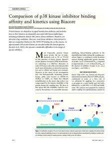
Fig. 1. Schematics of various photonic crystal waveguide-based SPR sensor implementations. a) Single mode planar photonic crystal waveguide-based SPR sensor. The dispersion relation of the core guided mode is in solid blue, that of the plasmon is in thick dashed red. Inset - coupler schematic; |Sz | of a plasmon (left) and a core mode (right). b) Solid core Bragg fiber-based SPR sensor. c) Microstructured core, honeycomb photonic crystal fiber-based SPR sensor.
the excitation by standard Gaussian laser sources. Near the point of phase matching, most of the energy launched into a waveguide core mode should be efficiently transferred into a plasmon mode. However, in the Total Internal Refraction (TIR) single mode waveguides with low refractive index-contrast, coupling with a plasmon is realized at essentially grazing angles of modal incidence on the metal layer. As follows from the basic SPR theory, coupling at such grazing incidence angles leads to an inevitable decrease of sensitivity of the SPR method. In principle, high index-contrast single mode waveguides could be employed to increase the angle of modal incidence on the interface. Overall, in the single mode waveguide-based sensors, phase matching between plasmon and fundamental waveguide mode is typically hard to realize. This is related to the fact that the effective refractive index of a core guided mode is close to the refractive index of the core material, which is typically larger than 1.45 due to practical material limitations. The effective refractive index of a plasmon is close to the refractive index of an ambient medium which is typically air na = 1 (gas sensing) or water na = 1.3 (biological sensing). Thus, large discrepancy in the effective indices makes phase matching between the two modes hard to achieve, with an exception of the high frequencies (λ < 650nm), where the plasmon dispersion relation deviates towards higher refractive indices. Thus, due to practical limitation on the lowest value of the waveguide core and cladding refractive indices, single mode TIR waveguide-based sensors were demonstrated almost exclusively in the visible where phase matching condition is easier to enforce. Problems with phase matching and loss of sensitivity due to shallow angles of incidence could be, in principle, alleviated by using multimode waveguides [20, 21, 22, 23, 24]. If launched properly, modal effective propagation angles in such waveguides can be much steeper, also resulting in smaller effective refractive indices. However, in multimode waveguides, only a certain number of higher order modes will be phase matched with a plasmon. Thus, sensitivity and stability of such sensors depend crucially on launch conditions. Moreover, as spatial field distribution in a Gaussian-like laser source is typically not well matched with the field distribution of a higher order mode of a multimode waveguide, only a small fraction of energy can be #84078 - $15.00 USD
(C) 2007 OSA
Received 12 Jun 2007; revised 22 Aug 2007; accepted 22 Aug 2007; published 24 Aug 2007
3 September 2007 / Vol. 15, No. 18 / OPTICS EXPRESS 11416
launched into such a mode resulting, again, in decreased sensitivity. In this paper, we present design principles of the novel photonic bandgap fiber-based SPR sensors, and show that they integrate advantages of both the single mode and multimode waveguide-based SPR sensors. Moreover, in photonic bandgap fiber-based SPR sensors, fundamental Gaussian-like leaky core mode can be phase matched with a plasmon at any desired wavelength of operation, thus enabling sensing anywhere from the visible to mid-IR. The term “leaky mode” generally refers to the guidance mechanism where effective refractive index of a propagating mode is smaller than that of the waveguide cladding. Such unusual modes are called leaky modes as, outside of a waveguide core, they tunnel through the finite size reflector, and finally radiate into a substrate. Leaky modes, therefore, are inherently lossy. When guided within a reflector bandgap, leaky modes decay exponentially with respect to distance into the microstructured cladding. The effective refractive indices of the leaky core modes can be arbitrarily smaller than that of a waveguide core material, thus enabling phase matching with a plasmon at any desirably frequency. Moreover, the lowest loss leaky core mode typically exhibits a Gaussian-like intensity distribution in the waveguide core region, thus enabling its convenient excitation by the Gaussian beam of an external light source. Using such a leaky mode for sensing gives the additional advantage of an effectively single mode propagation regime. In particular, when a set of modes is excited at a sensor input, higher order leaky modes radiate out faster than a fundamental mode. Consequently, after a certain propagation distance, only the lowest loss mode is left in the waveguide core. Finally, the effective angle of modal incidence onto a metal film, and hence sensitivity, can be varied at will by a proper selection of the waveguide core and reflector materials. Example of a planar photonic bandgap waveguide-based sensor (considered in great details in [28, 29]) operating at 800nm is shown in the inset of Fig. 1(a). There, a core of refractive index ncore = 1.5 is surrounded with a periodic photonic crystal reflector having refractive indices nh = 2.0 and nl = 1.5. The multilayer is covered with a thin gold layer facing aqueous analyte. Detailed analysis shows that the effective refractive index of a plasmonic wave at a gold-water interface at 800nm is ∼ 1.38. With a proper choice of the reflector layer thicknesses, one can then position reflector bandgap to be most efficient for guiding the core modes having refractive indices around that of the plasmon. In such a sensor, the core guided Gaussian-like mode (thick blue curve in the inset) is mostly confined to the waveguide core region, while the plasmon (thick dashed curve in the inset) is localized at the gold-water interface. Finally, by tuning the waveguide core size, one achieves phase matching between the two modes exactly at 800nm. In the rest of the paper, we present a theoretical study of SPR sensor designs based on the various types of photonic bandgap fibers, rather than planar waveguides. The advantages of the fiber based sensors over their planar counterparts include lower manufacturing cost, possibility of distributed sensing, and incorporation of microfluidics capabilities directly into the fibers. We start by designing sensors using solid core or analyte filled hollow core Bragg fibers (see Fig. 1(b)) operating at 633nm, 760nm, 1550nm. We argue that for plasmon excitation in the near-IR, the analyte filled hollow core Bragg fibers present a potent solution. We then present an SPR sensor based on a honeycomb photonic crystal fiber Fig. 1(c) operating at 1060nm. We further demonstrate a novel sensing mechanism based on the detection of breaking of an accidental degeneracy between the two plasmonic excitations. We conclude by summarizing major findings of the paper. 2.
SPR sensors using photonic crystal Bragg fibers
In this section, we propose two distinct approaches for fiber-based SPR sensing in aqueous solutions using respectively solid or hollow core photonic crystal Bragg fibers. In both cases, a thin gold layer is deposited on the outer surface of a Bragg fiber in direct contact with an #84078 - $15.00 USD
(C) 2007 OSA
Received 12 Jun 2007; revised 22 Aug 2007; accepted 22 Aug 2007; published 24 Aug 2007
3 September 2007 / Vol. 15, No. 18 / OPTICS EXPRESS 11417
analyte. By tailoring the dispersion relation of the core guided mode of a Bragg fiber, the phase matching condition is obtained at various wavelengths in the visible and near-IR. 2.1.
Large solid core Bragg fiber-based sensor
The first design approach consists of using the low loss HE11 Gaussian-like core mode of a Bragg fiber, and then lowering its effective refractive index towards that of a plasmon by the proper choice of the fiber reflector geometry and core size. The choice of the HE11 mode over other modes is motivated by its optimal spatial overlap with common Gaussian laser sources. Moreover, among other modes with angular momentum 1, HE11 typically exhibits the lowest loss. Thus, when long enough span of a Bragg fiber is used, an effectively single mode regime of operation can be achieved by the outward radiation of lossier modes, thus reducing the overall noise limit of the sensor. 1.47
nanalyte
1.46
nl gold layer
1.45
4
1.44
plasmon
ndgap
plasmon
1.43
µm
Re(neff)
3
TE, TM ba
2 core mode
ncore
1.42
core mode
1.41 1.4
1
1.39
Sz
1.38 0
0
a)
1
2
µm
3
4
Loss (dB/cm)
nh
5
8 7 6 nan.=1.331 nan.=1.332 5 4 3 2 1 0.6 0.61 0.62 0.63 0.64 0.65 0.66 0.67 0.68
λ (µm) 200 100 0
-100
nanalyte ~ 1.33
1.37 0.6 0.61 0.62 0.63 0.64 0.65 0.66 0.67 0.68
b)
Sensitivity (1/RIU)
5
λ (µm)
-200 0.6 0.61 0.62 0.63 0.64 0.65 0.66 0.67 0.68
c)
λ (µm)
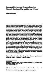
Fig. 2. Large solid core photonic crystal Bragg fiber-based SPR sensor. a) Schematic of the sensor. The low refractive index core is surrounded by a concentric photonic crystal reflector. Outside, the reflector is goldplated for plasmon excitation. The gold layer is bordered by an aqueous analyte. The energy flux distribution across the fiber cross-section is shown with a solid curve for the fundamental core mode, and with a dashed curve for the plasmonic mode. b) Band diagram of the sensor modes showing the dispersion relation of the fundamental core mode (thick solid curve), and plasmonic mode (dashed curve). Common part of the TE, TM bandgaps of a periodic planar reflector is shown as a clear region, while gray regions correspond to the continuum of bulk reflector states. In a large core Bragg fiber, the effective refractive index of the fundamental core mode is close to the refractive index of the core material. c) Upper part: solid curve shows loss of the fundamental core mode near the phase matching point with the plasmon. The modal loss reaches its maximum at the phase matching wavelength. The dashed line shows a shift of the modal loss curve when the refractive index of the analyte is varied. Lower part: computed dependence of the sensor amplitude sensitivity over wavelength.
Particularly, we consider solid core photonic crystal Bragg fibers made of two materials with refractive indices nl = 1.42 and nh = 1.60. Prototypes of such fibers have been recently fabricated in our group by using a poly(vinylene difloride) (PVDF)/polycarbonate (PC) material combinations [36]. In such fibers, a solid core of refractive index nl is surrounded by N alternating high and low refractive index reflector layers of thicknesses dl , and dh (see Fig. 2). A typical choice of the reflector layer thicknesses follows the quarter wave relation [37]:
λc dl,h = q , 2 4 nl,h − n2e f f (λc )
#84078 - $15.00 USD
(C) 2007 OSA
(1)
Received 12 Jun 2007; revised 22 Aug 2007; accepted 22 Aug 2007; published 24 Aug 2007
3 September 2007 / Vol. 15, No. 18 / OPTICS EXPRESS 11418
where λc is the operating wavelength and ne f f (λc ) is a desired effective refractive index of a bandgap guided core mode at that wavelength. This choice of the reflector parameters, guarantees efficient bandgap guidance at λc of a mode with effective refractive index ne f f (λc ), however, it does not guarantee the existence of such a mode. As it will be detailed in the following, one way of positioning a core mode dispersion relation inside of a fiber bandgap is by varying the fiber core diameter dc . Namely, in the large core diameter Bragg fibers with dc ≫ λc , the effective refractive index of the fundamental core mode is close to that of the core material. By decreasing the fiber core size, one can consistently reduce the core mode effective refractive index. In the context of SPR sensing, λc also corresponds to the wavelength of desired phase matching between a plasmon and a core mode. Then, a reasonable approximation to ne f f (λc ) is a value close to that of the effective refractive index of a plasmonic wave propagating at a planar gold-analyte interface: εgold (λc )εa (λc ) , (2) n2e f f (λc ) ≃ εgold (λc ) + εa (λc ) where εa is the dielectric constant of the analyte and εgold is the dielectric constant of the gold layer approximated by the Drude model:
εgold = ε∞ −
(λ /λ p )2 , 1 + i(λ /λt )
(3)
where ε∞ = 9.75, λt = 13.0µ m, λ p = 0.138µ m. With these choices of ne f f (λc ) and λc , we are still left with two free parameters, which are the number of layers N in the Bragg reflector, and the fiber core size dc . In metallized Bragg fibers, guided modes incur additional losses due to high absorption of the metal film. When operating within the bandgap of a Bragg fiber reflector, the fields of a leaky core mode decay exponentially into the periodic reflector. Therefore, modal presence in the metallized region also decreases exponentially with respect to the number of reflector layers. Thus, variation in the number of reflector layers will primarily effect the core mode propagation loss. We now investigate in more details the effect of the core size on the modal structure of an SPR sensor. First, we consider a Bragg fiber sensor having large core diameter dc = 6µ m, operating in the vicinity of λc = 633nm, and featuring a 4 layer reflector plated with a 40nm thick layer of gold (see Fig. 2(a)). Reflector layer thicknesses are chosen in accordance with (1) with ne f f = 1.4, thus resulting in dl = 666nm, dh = 204nm. More than 99% of the modal energy is confined within the core. In Fig. 2(b) we present the band diagram of thus defined Bragg fiber sensor. Common TM, TE bandgap of a corresponding infinitely periodic Bragg reflector is presented as a clear region, while gray regions signify a continuum of reflector bulk states. For a large core photonic crystal Bragg fiber, the effective refractive index of the lowest loss leaky mode (thick solid line) is close to that of the refractive index of the core material (thin solid line). The dispersion relation of the plasmon mode is shown as thick dashed line. By a proper design of the Bragg fiber reflector, the dispersion relations of the core guided and plasmonic modes near λc are positioned well inside of the reflector band gap. Therefore, the fundamental core mode (solid curve in Fig. 2(a)) is well confined within the Bragg fiber core, while the plasmon mode (dashed curve in Fig. 2(a)) is mostly confined to the metal coating and the last reflector layer. By design, the phase matching between the core and plasmonic modes is achieved at 634nm ≃ λc . In the upper plot of Fig. 2(c), the propagation loss of the core mode is presented as a function of wavelength. As seen from this figure, the loss of the core mode peaks at the wavelength of phase matching with the plasmon mode. Near this phase matching point, the fields of the core guided mode contain a strong plasmonic contribution. As the plasmon exhibits very high #84078 - $15.00 USD
(C) 2007 OSA
Received 12 Jun 2007; revised 22 Aug 2007; accepted 22 Aug 2007; published 24 Aug 2007
3 September 2007 / Vol. 15, No. 18 / OPTICS EXPRESS 11419
propagation loss, that of the core mode will also exhibit sharp increase near the phase matching point. An important aspect of the proposed setup is the freedom of adjusting the loss of the core mode. As penetration of the leaky mode reduces exponentially within the multilayer reflector, the coupling strength between the plasmon and core modes can be controlled by changing the number of reflector layers situated between the waveguide core and the metal film. Ultimately, higher coupling strength leads to higher modal losses, hence, shorter sensor length. When the real part of the analyte refractive index is varied, the plasmon dispersion relation displaces accordingly, thus leading to a shift in the position of the phase matching point with the core guided mode. Consequently, in the vicinity of the phase matching point, the loss of the core guided mode varies strongly with changes in the analyte refractive index (see the upper part of Fig. 2(c)). The simplest mode of operation of such a fiber-based SPR sensor consists of a detection of small changes in the bulk refractive index of an analyte. There are two main modalities of SPR detection - amplitude based and spectral based. In the amplitude based approach, all the measurements are performed at a single wavelength. The advantage of this method is its simplicity and low cost as no spectral manipulation is required. The disadvantage is a smaller operational range and lower sensitivity when compared to the wavelength interrogation approach in which transmission spectra are taken and compared before and after the change in the analyte has occurred. We start by describing a single wavelength, amplitude based detection method. We define α (λ , na ) to be the transmission loss of the core mode as a function of the wavelength and refractive index of the analyte na . Considering P0 to be the power launched into the fiber core mode, the power detected after propagation along the sensor of length L will be P(L, λ , na ) = P0 exp(−α (λ , na )L). For the operational wavelength λ , the amplitude sensitivity to the dna change in the analyte refractive index can then be defined as SA (λ )[RIU −1 ] = (P(L, λ , na + dna ) − P(L, λ , na ))/P(L, λ , na )/dna . The sensor length L is typically limited by the modal transmission loss. A reasonable choice of a sensor length is L = 1/α (λ , na ), which falls into a ∼ 1cm range for the large core Bragg fiber-based sensor described in this section. Such choice of a sensor length results in a simple definition of sensitivity for the small changes in the analyte refractive index SA (λ )[RIU −1 ] =
1 1 ∂ P(L, λ , na ) ∂ α (λ , na ) =− . P(L, λ , na ) ∂ na α (λ , na ) ∂ na
(4)
In the lower part of Fig. 2(c) we present the amplitude sensitivity of the computed large core Bragg fiber-based SPR sensor. The maximal sensitivity is achieved at 644nm and equals to 214RIU −1 . It is typically a safe assumption that a 1% change in the transmitted intensity can be detected reliably, which leads to the sensor resolution of 4.7 · 10−5 RIU. In the wavelength interrogation mode, changes in the analyte refractive index are detected by measuring the displacement of the plasmonic peak λ peak . In this case, sensitivity is defined as Sλ [nm · RIU −1 ] =
d λ peak (na ) . dna
(5)
In the case of a large core Bragg fiber-based sensor we find that the corresponding spectral sensitivity is 1900nm · RIU −1 . It is typically a safe assumption that a 0.1nm change in the position of a resonance peak can be detected reliably, which leads to a sensor resolution of 5.3 · 10−5 RIU. 2.2.
Small solid core Bragg fiber-based sensor
With this second design, we explore the possibility of considerably reducing the effective refractive index of the core mode by reducing the fiber core size. This enables plasmonic excitation to take place at higher wavelengths in the near-IR. Thus, with the same overall structure of #84078 - $15.00 USD
(C) 2007 OSA
Received 12 Jun 2007; revised 22 Aug 2007; accepted 22 Aug 2007; published 24 Aug 2007
3 September 2007 / Vol. 15, No. 18 / OPTICS EXPRESS 11420
nh
1.46 1.45
nl
6
gold layer
1.44
5 Sz
plasmon core mode
Re(neff)
µm
M ban
dgap
1.43
4 3
TE, T
1.42
ncore
1.41 1.40
plasmon
1.39
2
core mode
1.38 1 0 0
a)
1.37 1
2
3
µm
4
5
6
nanalyte ~ 1.33
1.36 0.7
b)
0.72
0.74
0.76
λ (µm)
0.78
0.8
Sensitivity (1/RIU)
nanalyte
Loss (dB/cm)
a Bragg reflector as in the prior case, by reducing the fiber core diameter down to dc = 1.8m, the plasmonic excitation at the interface with aqueous analyte is demonstrated at 760nm. 7 6 5 4 3 2 1 0 0.7
nan.=1.328
nan.=1.327
0.72
0.74
0.76
0.78
0.8
0.78
0.8
λ (µm) 300 200 100 0 -100 -200 -300 0.7
c)
0.72
0.74
0.76
λ (µm)
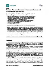
Fig. 3. Small solid core photonic crystal Bragg fiber-based SPR sensor. a) Schematic of the sensor. A low refractive index core is surrounded by a concentric photonic crystal reflector. Outside, the reflector is goldplated for plasmon excitation. The gold layer is bordered by an aqueous analyte. The energy flux distribution across the fiber cross-section is shown with a solid curve for the fundamental core mode, and with a dashed curve for the plasmonic mode. b) Band diagram of sensor modes. Dispersion relation of the fundamental core mode (thick solid curve), and plasmonic mode (dashed curve). The common part of the TE, TM bandgaps of a periodic planar reflector is shown as a clear region, while gray regions correspond to the continuum of bulk reflector states. In a small core Bragg fiber, the effective refractive index of the fundamental core mode can be much smaller than the refractive index of the core material. c) Upper part: the solid curve shows loss of the fundamental core mode near the phase matching point with the plasmon. The modal loss reaches its maximum at the phase matching wavelength. The dashed line shows a shift of the modal loss curve when the refractive index of the analyte is varied. Lower part: computed dependence of the sensor amplitude sensitivity on wavelength.
In Fig. 3(a) we show a cross-section of the small solid core photonic crystal Bragg fiber sensor, and the energy flux distributions in its leaky HE11 core mode and plasmonic mode. Reflector layer thicknesses were chosen according to (1) with nl = 1.42, nh = 1.6, λc = 760nm and ne f f = 1.39, thus resulting in dl = 654nm, dh = 240nm. The total number of layers is N = 12. The amount of energy in the core is 78%. In Fig. 3(b) we present the band diagram of thus defined Bragg fiber sensor. Common TM, TE bandgap of a corresponding infinitely periodic Bragg reflector is presented as a clear region, while gray regions signify a continuum of reflector bulk states. In this small core photonic crystal Bragg fiber, the effective refractive index of the core guided HE11 mode (thick solid line) can be considerably smaller than the refractive index of a core material (thin solid line). Dispersion relation of the plasmon mode is shown as thick dashed line. In this particular case, the dispersion relation of the core guided mode is shifted towards the lower edge of the reflector bandgap, therefore, the core mode (solid curve in Fig. 3(a)) and plasmonic mode (dashed curve in Fig. 3(a)) are not strongly confined, penetrating significantly into the reflector region. The phase matching between the core and plasmonic modes is achieved at 758nm ≃ λc . In the upper plot of Fig. 3(c), the propagation loss of the core mode is presented as a function of the wavelength. As seen from this figure, it peaks at the wavelength of phase matching with the plasmon mode. In the lower part of Fig. 3(c), we present the amplitude sensitivity (4) of the proposed small solid core Bragg fiber-based SPR sensor. Maximal sensitivity is achieved at 788nm and is equal to 293 · RIU −1 . Assuming that a 1% change in the transmitted intensity #84078 - $15.00 USD
(C) 2007 OSA
Received 12 Jun 2007; revised 22 Aug 2007; accepted 22 Aug 2007; published 24 Aug 2007
3 September 2007 / Vol. 15, No. 18 / OPTICS EXPRESS 11421
can be detected reliably, this leads to a sensor resolution of 3.4 · 10−5 RIU. Finally, we find that the corresponding spectral sensitivity (5) is 10200nm · RIU −1 . Assuming that a 0.1nm change in the position of a resonance peak can be detected reliably, this leads to a sensor resolution of 9.8 · 10−6 RIU. The sensor length in this case is in a ∼ 1cm range. 2.3.
Analyte-filled hollow-core Bragg fiber-based sensor
When designing fiber-based SPR sensors in the near-IR, one faces a difficult problem of phase matching a plasmon with a core guided mode. The reason for such difficulty is the fact that, in this spectral region, the effective refractive index of a plasmon becomes very close to that of an analyte, which for aqueous solutions, for example, is na ∼ 1.32. As described in the previous section, to lower the effective refractive index of a core guided mode to that of a plasmon, one can use a small solid core Bragg fiber with a properly positioned bandgap region. In that case, however, fiber core size becomes too small for convenient coupling. To resolve this problem, we suggest using a large analyte-filled hollow core Bragg fiber shown in Fig. 4(a). In this case, as described earlier, the effective refractive index of a core mode (thick solid line in Fig. 4(b)) is close and somewhat smaller than the refractive index of the core material (analyte). In turn, the plasmon refractive index (dashed line in Fig. 4(b)) is close and somewhat larger than the refractive index of the analyte. To enable phase matching between the core mode and the plasmon, one has to force the core mode to cross over the radiation line of the analyte. As detailed in [38], to force such a crossing, one has to introduce a defect into the structure of the reflector so as to induce anticrossing of the core mode with a reflector defect state (marked as a dashed circular region in Fig. 4(b)). The particular sensor geometry implementing this design principle is presented in Fig. 4(a). In this sensor, an analyte-filled fiber core of diameter dc = 10µ m is surrounded by an 18 layer reflector with alternating refractive indices nl = 1.42, and nh = 1.6. In accordance with (1) where λc = 1550nm and ne f f = 1.3109, all the low refractive index layers, with an exception of the 18th layer, have thicknesses dl = 710nm; all the high refractive index layers, with an exception of the first one, have thicknesses of dh = 422nm. On the outside, the reflector is plated with a 40nm gold layer. Two defects are incorporated into the structure of the Bragg reflector. The first defect is introduced by halving the outer layer thickness to 355nm. This defect is introduced to get rid of an unwanted surface state at the fiber metal-analyte interface. The second defect is introduced into the first high refractive index layer which thickness is increased to 1005nm. The high refractive index defect created by the first layer of the reflector attracts a localized state that causes anticrossing with the core mode, thus forcing the core mode to cross over the dispersion relation of the analyte, and enabling phase matching with the plasmon. The main disadvantage of this plasmon excitation mechanism is that the intensity distribution in a crossed-over core mode, is not Gaussian-like anymore. In fact, such a mode is evanescent in the analyte region, hence, it becomes somewhat difficult to excite it with a common Gaussian laser source. However, when the plasmon dispersion relation is very close to that of the analyte (as it is the case in the near-IR), then evanescent tail of a crossed-over core mode can extend substantially into the analyte filled core region, thus simplifying considerably coupling to such a mode. For example, design of Fig. 4(a) enables phase matching with a plasmon at 1550nm (as seen from Fig. 4(b)). At this wavelength, the crossed-over core mode still has 29% of its energy concentrated in the analyte filled hollow fiber core. We conclude with sensitivity analysis of the proposed near-IR SPR sensor. In the lower part of Fig. 4(c), we present the sensor amplitude sensitivity (4). the maximal sensitivity is achieved at 1561nm and is equal to 365 · RIU −1 . Assuming that a 1% change in the transmitted intensity can be detected reliably, this leads to a sensor resolution of 2.7 · 10−5 RIU. Finally, we find that
#84078 - $15.00 USD
(C) 2007 OSA
Received 12 Jun 2007; revised 22 Aug 2007; accepted 22 Aug 2007; published 24 Aug 2007
3 September 2007 / Vol. 15, No. 18 / OPTICS EXPRESS 11422
1.34
nh
core mode after crossing over
nl
14
1.32
plasmon
8 6
1.31 1.3
4
0
1.29
core mode
anticrossing with a reflector defect state TE
,T
M
ba
nd
0
a)
2
4
6
8
µm
10
12
14
16
1.28 1.5
b)
1.54
80
core mode
ga p
1.58
1.62
λ (µm)
1.66
1.7
nan.=1.311
nan.=1.312
60 40 20 0 1.5
ncore = nanalyte Sensitivity (1/RIU)
Sz
10
µm
1.33
gold layer
plasmon
12
2
Loss (dB/cm)
nanalyte
Re(neff)
16
400 300 200 100 0 -100 -200 -300 1.5
c)
1.52
1.54
1.56
1.58
1.6
1.58
1.6
λ (µm)
1.52
1.54
1.56
λ (µm)
Fig. 4. Analyte-filled large hollow core photonic crystal Bragg fiber-based SPR sensor. a) Schematic of the sensor. The analyte-filled hollow core is surrounded by a concentric photonic crystal reflector. Outside, the reflector is goldplated for plasmon excitation. The gold layer is bordered by an aqueous analyte. The energy flux distribution across the fiber crosssection is shown in solid curve for the fundamental core mode, and in dashed curve for the plasmonic mode. b) Band diagram of sensor modes. Dispersion relation of the fundamental core mode crossing over the analyte light line (thick solid curve), and plasmonic mode (dashed curve). Common part of the TE, TM bandgaps of a periodic planar reflector is shown as a clear region, while gray regions correspond to the continuum of bulk reflector states. In a large analyte-filled hollow core Bragg fiber, the effective refractive index of the fundamental core mode is close to the refractive index of the analyte. By introducing a defect into the multilayer structure, one can force a core mode to cross over the analyte radiation line. c) Upper part: solid curve shows loss of the crossed-over core mode near the phase matching point with the plasmon. The modal loss reaches its maximum at the phase matching wavelength. The dashed line shows a shift of the modal loss curve when the refractive index of the analyte is varied. Lower part: dependence of the sensor amplitude sensitivity on wavelength.
the corresponding spectral sensitivity (5) is 7000nm · RIU −1 . Assuming that a 0.1nm change in the position of a resonance peak can be detected reliably, this leads to a sensor resolution of 1.4 · 10−5 RIU. The sensor length in this case is in ∼ 1mm range. 3.
SPR sensors using microstructured photonic crystal fibers
In the previous section we have presented several design strategies for the SPR sensors based on photonic crystal Bragg fibers. In principle, any photonic bandgap fiber can be used in place of a Bragg fiber to develop such sensors. In this section we present an example of a SPR sensor based on a solid core honeycomb photonic crystal fiber. Moreover, novel sensing mechanism is discussed, where splitting of an accidentally degenerate plasmonic peak into two peaks is used for detection of changes in the analyte refractive index. In Fig.5(a) Schematic of a honeycomb photonic crystal fiber-based SPR sensor is presented. The design parameters are chosen as follows, the center to center distance between adjacent holes is Λ = 0.77µ m, the cladding hole diameter is d = 0.55Λ, the diameter of the hole in the core center is dc = 0.35Λ. The fiber is made of silica glass with a refractive index of nglass = 1.45, the core and cladding holes are filled with air nair = 1, while the large semi-circular channels are plated with a 40nm thick layer of gold and filled with an aqueous analyte na = 1.32. The central hole in the fiber core lowers its effective refractive index compared to that of a silica cladding. Under certain conditions, such a core can support a mode confined by the bandgap of the honeycomb reflector. The core guided mode in such a fiber is analogous to that of the #84078 - $15.00 USD
(C) 2007 OSA
Received 12 Jun 2007; revised 22 Aug 2007; accepted 22 Aug 2007; published 24 Aug 2007
3 September 2007 / Vol. 15, No. 18 / OPTICS EXPRESS 11423
1.336 1.334 1.332
Λ
dc
2Λ
Re(neff)
nanalyte
d
nan.=1.322
core mode
III
core mode
II
(IV)
(III)
IV
plasmon (analyte) I
1.326
double plasmon and core mode excitaion
1.324 0.99
b)
plasmon (analyte)
nan.=1.32
gold layers
a)
(II)
plasmon (cladding)
1.33 1.328
(I)
Photonic Bandgap
plasmon (cladding)
1
1.01
λ (µm)
double plasmon and core mode excitation
1.02
c)
Fig. 5. Solid core honeycomb photonic crystal fiber-based SPR sensor. a) Schematic of the sensor. The solid core having a small central hole is surrounded with a honeycomb photonic crystal reflector. Two large channels are integrated to implement analyte access to the fiber reflector region. The channels are goldplated for plasmon excitation. The gold layer is bordered by an aqueous analyte. b) Band diagram of sensor modes. Dispersion relation of the fundamental core mode ( thick solid curve), analyte bound plasmonic mode (dashed curve with circles), and cladding bound plasmonic mode (dashed curve). The bandgap of an infinitely periodic reflector is shown as a clear region. c) The energy flux distributions across the fiber cross-section are shown for the fundamental core mode (II) as well as the analyte and cladding bound plasmon modes (I,III) outside of the phase matching region. The energy flux distribution is also shown for the fundamental core mode at the phase matching point (IV) showing strong mixing of the fundamental core mode with plasmonic modes.
small solid core Bragg fiber discussed earlier. Guided by the bandgap of the fiber reflector, the effective refractive index of the core mode can be made much lower than that of the silica material. Moreover, as in the case of photonic crystal Bragg fibers, radiation loss of a bandgap guided core mode can be reduced by adding more layers into the honeycomb reflector. The main reason why we chose a honeycomb structure of the fiber reflector is because it enables a very large photonic bandgap [39, 40], thus simplifying considerably phase matching of the core guided and plasmonic modes. Unlike planar metal/dielectric interface that supports a single plasmonic excitation, finite size, microstructured metal layer separating two dielectrics can support multiple plasmonic modes [26, 27]. Thus, when tracking losses of a core guided fiber mode as a function of wavelength, one typically observes several plasmonic peaks corresponding to phase matching between the core mode and various plasmonic modes. Particularly, one of the plasmonic modes will have most of its energy concentrated in one of the neighboring dielectrics, while the other plasmonic excitation will have most of its energy concentrated in the other neighboring dielectric. In principle, simultaneous detection of changes in several plasmonic peaks can improve sensor sensitivity; additionally it gives a natural reference point in the measurements. In the case of a honeycomb photonic crystal fiber-based sensor we design the fiber so that two plasmonic peaks are degenerate at 1009nm with nanalyte = 1.32. Fig. 5(b) shows the dispersion relations of the Gaussian-like core mode (thick solid line), analyte bound plasmonic mode (thin solid line with circles) and cladding bound plasmonic mode (thick solid line). These dispersion relationes are positioned well inside the bandgap of an infinite honeycomb reflector, which can be confirmed by the plane wave method [40]. Corresponding flux distributions of the core guided and plasmonic modes are presented in Fig. 5(c). The core mode loss shows a single plasmonic peak (solid curve in Fig. 6(a)). When the refractive index of the analyte is varied,
#84078 - $15.00 USD
(C) 2007 OSA
Received 12 Jun 2007; revised 22 Aug 2007; accepted 22 Aug 2007; published 24 Aug 2007
3 September 2007 / Vol. 15, No. 18 / OPTICS EXPRESS 11424
−1
Ampltuide Sensitivity (RIU )
300
Loss (dB/cm)
250 200
nan.=1.32
150
nan.=1.322
100
a)
∆λpeak
50 0.94
0.96
0.98
1
λ (µm)
1.02
1.04
1.06
500 400 300 200
0
−100 0.94
b)
two plasmon excitation region
100
0.96
0.98
1
λ (µm)
1.02
1.04
1.06
Fig. 6. Sensitivity of the honeycomb photonic crystal fiber-based SPR sensor. a) The solid curve shows loss of the fundamental core mode near the degenerate phase matching point with two plasmonic modes and nanalyte = 1.32. Due to degeneracy, only one peak is distinguishable in the loss curve. Dashed line shows splitting of the degeneracy in plasmonic modes when the analyte refractive index is changed to nanalyte = 1.322. b) Dependence of the sensor amplitude sensitivity on wavelength.
this affects the two plasmonic dispersion relations differently. Particularly, the analyte bound plasmon mode is affected much strongly by the changes in the analyte refractive index than the cladding bound plasmonic mode. As a result, degeneracy is lifted, and two closely spaced plasmonic peaks appear in the core mode loss curve (dashed curve in Fig. 6(a)). For example, a 0.002 change in the analyte refractive index splits a single plasmonic peak into two peaks separated by 27.5nm. This permits a novel spectral detection technique, where relative peak separation can be used to characterize changes in the analyte refractive index. By defining spectral sensitivity as: (6) Sλ = |λ peak1 − λ peak2 |/dnanalyte , we find spectral sensitivity of 13750nm · RIU −1 . It is typically a safe assumption that a 0.1nm change in the position of a resonance peak can be detected reliably, which results in a sensor resolution of 7.2·10−6 RIU, which is, to our knowledge, the highest reported spectral sensitivity of an aqueous fiber-based SPR sensor. Finally, in Fig. 6(b), we present the amplitude sensitivity of the proposed honeycomb photonic crystal fiber-based sensor as defined by 4. The maximal sensitivity is achieved at 1009nm and equals to 400 · RIU −1 . It is typically a safe assumption that a 1% change in the transmitted intensity can be detected reliably, which leads to a sensor resolution of 2.5 · 10−5 RIU. It is interesting to note that for this sensor design, the sensitivity curve has a single maximum, unlike the sensitivity curves associated with the Bragg fiber designs reported in the preceding section. Sensor length in this case is in ∼ 1mm range. 4.
Conclusion
In conclusion, we have presented a novel approach to the design of photonic crystal fiberbased SPR sensors for measuring changes in low refractive index analytes. In such sensors, a Gaussian-like fiber core mode is phase matched with a surface plasmon propagating along the metallized fiber microstructure. Due to bandgap guidance, operational wavelength of such sensors can be designed anywhere from the visible to near-IR. Moreover, a wide variety of material combinations can be used to design such a sensor as there is no limitation on the upper value of the waveguide core refractive index. Finally, the coupling strength between the #84078 - $15.00 USD
(C) 2007 OSA
Received 12 Jun 2007; revised 22 Aug 2007; accepted 22 Aug 2007; published 24 Aug 2007
3 September 2007 / Vol. 15, No. 18 / OPTICS EXPRESS 11425
waveguide core and plasmon modes can be varied by changing the number of the photonic crystal reflector layers, which also permits designing the overall sensor length. The methodology for the photonic crystal waveguide-based SPR sensor design is quite general and its particular implementation can be based on metal plated planar integrated photonic crystal waveguides, Bragg fibers or microstructured photonic crystal fibers. Particularly, one starts with a choice of an operational wavelength λc . Then, plasmon effective refractive index ne f f (λc ) at λc is approximated by a value close to the effective refractive index of a plasmon excitation on a planar metal-analyte interface (2). For a given λc , this allows to center the photonic bandgap of a waveguide reflector around ne f f (λc ). By varying the waveguide core size (or by varying the microstructure of the core), one can shift the dispersion relation of a core mode towards that of a plasmonic mode until phase matching occurs at λc . The sensor length can be changed by varying the number of layers in a photonic crystal reflector, with larger reflectors resulting in the longer sensors. Finally, we have presented examples of the aqueous SPR sensors based on the planar photonic crystal waveguide, solid and analyte filled Bragg fibers, as well as solid core microstructured photonic crystal fiber. The amplitude sensitivity of the proposed designs was as high as 400 · RIU −1 . Assuming that a 1% change in the transmitted intensity can be detected reliably, a sensor resolution as good as 2.5 · 10−5 RIU was demonstrated. The spectral sensitivity of the proposed designs was as high as 13750nm · RIU −1 . Assuming that a 0.1nm change in the position of a plasmonic loss peak can be detected reliably, a sensor resolution as good as 7.2 · 10−6 RIU was demonstrated. The sensor lengths in our examples varied from a mm to a cm range. For measuring changes in the aqueous analyte refractive index, the sensitivities of our fiber designs surpass those of the best existing waveguide-based sensor designs [41]. Acknowledgments This work is supported in part by the Canada Institute for Photonic Innovations grants BP5 and FP3, Canada Research Chair program, and NSERC Strategic grant “Miniaturized Si-based plasmonics platform for gas detection.”
#84078 - $15.00 USD
(C) 2007 OSA
Received 12 Jun 2007; revised 22 Aug 2007; accepted 22 Aug 2007; published 24 Aug 2007
3 September 2007 / Vol. 15, No. 18 / OPTICS EXPRESS 11426