Aug 16, 2006 - Photonic Crystal Lens: From Negative Refraction and Negative Index to Negative Permittivity and Permeability. T. Decoopman,1,2 G. Tayeb,1 ...
PHYSICAL REVIEW LETTERS
PRL 97, 073905 (2006)
week ending 18 AUGUST 2006
Photonic Crystal Lens: From Negative Refraction and Negative Index to Negative Permittivity and Permeability T. Decoopman,1,2 G. Tayeb,1 S. Enoch,1 D. Maystre,1 and B. Gralak1 1
Institut Fresnel, UMR CNRS 6133, Faculte´ des Sciences et Techniques, case 161, Universite´ Paul Ce´zanne Aix-Marseille III, 13397 Marseille Cedex 20, France 2 Institut d’Electronique, de Microe´lectronique et de Nanotechnologie, UMR CNRS 8520, Universite´ des Sciences et Technologies de Lille, 59 652 Villeneuve d’Ascq, Cedex, France (Received 30 January 2006; published 16 August 2006) We consider a dielectric photonic crystal made of cylindrical holes in a high index matrix. We show that a given finite size photonic crystal can mimic a homogeneous material whose permittivity and permeability are negative. We pay attention to the limitation of the homogeneous medium model and the vital role of the truncation of the crystal. DOI: 10.1103/PhysRevLett.97.073905
PACS numbers: 42.70.Qs, 78.20.Ci
A seminal paper by Pendry published in 2000 has opened a new research line: the metamaterials [1]. Following a work published in 1968 by Veselago, Pendry proposed to build a lens using a slab of material whose permittivities and permeability should be both equal to minus one [1,2]. The tremendous result he obtained is that this slab would act as a perfect lens, i.e., that the diffraction limit would be overcome. Huge practical and theoretical implications could be foreseen and there has been a lot of debate about the possibility to obtain perfect focusing [3,4] and also about the limits of actual devices [5]. Unfortunately, nature does not provide us with such a material; thus, researchers have proposed to build a composite material that would mimic its properties, i.e., a metamaterial. Thanks to the "double C resonators" structure negative refraction has been demonstrated [6]. When visible light is considered, metals become lossy. In order to overcome this difficulty, the use of purely dielectric structures can be envisaged. Moreover, it has been shown that losses will necessarily limit the performances of a metamaterial lens [4]. However, it should be noticed that recent results have shown the metallic device to be relevant at optical wavelength [7]. Negative refraction using dielectric photonic crystal was demonstrated before light was shed on metamaterials [8]. Yablonovitch and John have proposed photonic crystals simultaneously, but with different aims [9,10]. Recently some papers have shown that the richness of the dispersion relation of Bloch modes propagating in photonic crystals can give birth to several interesting effects such as superprism effect, self-guiding, or negative refraction [8,11–13]. It was consequently a natural following step to consider the possibility of building lenses using negative refraction in dielectric photonic crystals [14,15]. Several experimental papers have demonstrated negative refraction and even focusing effects generated by dielectric photonic crystals [16 –20]. However, though the idea of an effective permeability of a dielectric material 0031-9007=06=97(7)=073905(4)
is not new [21], the question of the determination of the effective permittivity and permeability of a dielectric lefthanded metamaterial has been rarely addressed [14,22]. Our main objective in this Letter is to show that negative effective permeability and permittivity can be defined under certain conditions for a dielectric photonic crystal that exhibits negative refraction. Especially, we show that, by contrast with usual homogeneous materials, the effective permeability and permittivity strongly depend on the boundary of the crystal. Negative refraction in photonic crystals is the consequence of the conservation of the tangential component of the wave vector at the boundary of a slab of photonic crystal and of specific features of the dispersion relation of the Bloch modes [11]. Let us recall that the average energy velocity ve is equal to the group velocity vg and is given by ve � vg � gradk �!�, and thus is perpendicular to the constant frequency dispersion diagram (i.e. the extremity of the possible Bloch wave vectors at a given frequency). Thus, one can define an effective optical index, whose meaning is that the mean energy propagation direction will be refracted at the boundary of the crystal following a Snell-Descartes law with a negative index. Note that this definition does not rely on any properties of the phase velocity inside the crystal. Some additional conditions should be added to this definition. Indeed, in order to be able to use this definition one should take care about the shape of the constant frequency dispersion diagram. For a homogeneous isotropic material with optical index n this diagram would be a sphere of radius k � n�!=c� and, thus, so should be the diagram of a metamaterial. Eventually, an ellipsoid could be obtained if one wants to simulate an anisotropic homogeneous material. Note that we assume also that only one band exists at the frequency of interest. At last, the analysis proposed in Ref. [11], for example, is valid only if the slab of photonic crystal can be considered as a grating; i.e., the photonic crystal truncation at its boundary with the
073905-1
© 2006 The American Physical Society
week ending 18 AUGUST 2006
PHYSICAL REVIEW LETTERS
PRL 97, 073905 (2006)
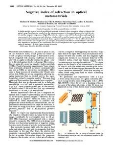
external medium should be such that the interface is periodic and moreover at the wavelength of interest only one propagative order should exist. For the sake of simplicity we will consider here a twodimensional (2D) photonic crystal and the electromagnetic field is assumed to be invariant along the axis of the rods (z axis). Furthermore, we assume also that the crystal is made of vacuum cylinders with circular cross section drilled in a dielectric matrix. The parameters have been chosen from Ref. [23]. Figure 1 shows the dispersion relation of the Bloch modes in the crystal for E k polarization (the electric field is parallel to the cylinders) and H k polarization (the magnetic field is parallel to the cylinders). In order to find a wavelength at which the effective optical index would be minus one, we should seek for a negative slope of the dispersion relation and a constant frequency diagram as close as possible to a circle with radius k0 � !=c � 2�=�0 . The solid slanting right line passing through point A in Fig. 1 represents the dispersion relation of plane waves in vacuum. Thus, the intersection between this line and the second band in E k polarization (point labeled A) gives the frequency !0 of interest, since moreover it can be verified (see the inset in Fig. 1) that the constant frequency diagram at !0 is reasonably close to the circle with radius k0 , and thus all the required conditions in order to get an effective optical index neff � �1 are fulfilled. To validate our solution, we have computed the field when a limited beam at frequency !0 illuminates the structure (see Fig. 2). The calculations have been carried out using the scattering matrix method (also called multipole method or Rayleigh method) developed a few years ago and recently extended to be able to cope with a limited extent of the homogenous dielectric surrounding the rods [24 –26]. This method, whose origin can be found in the work done by Rayleigh [27], is also known in solid-state physics as the K. K. R. method [28,29]. As expected, the
beam is negatively refracted with an angle opposite to the incidence angle showing the validity of our analysis. Another feature should be noted: the transmitted energy rate is relatively low; about 73% is reflected in normal incidence. Let us conjecture that this result can be interpreted as follows: the propagation direction is given by the conservation of the tangential component of the Bloch wave vector, allowing us to define the effective optical index, that is to say the product of the permittivity and the permeability. But, if one wants to define effective permittivity "eff and permeability �eff , any combination with �eff � n2eff ="eff will obviously be acceptable. However, the different values lead to different surface impedances and thus to different reflection coefficients. According to this model, our interpretation is that in our case the photonic crystal mimics a homogeneous material with �eff � 1="eff � �1. Let us emphasize that a priori both "eff and �eff are complex and, provided that their product is real, the material is lossless. In the simplest case of 1D photonic crystals it can be shown that both are real only when the elementary cell has a top-down symmetry [30]. This emphasizes how important the role of the interface is. In order to check our hypothesis we achieved a numerical experiment. Is it possible to find the characteristics of an external homogeneous medium in such a way that the photonic crystal does not diffract the incident wave? We consider the finite size photonic crystal identical to that of Fig. 2, but surrounded by a homogeneous material with �eff � 1="eff , both parameters being negative. Then, we make the permittivity vary and look for a minimum of the integral around the crystal of the difference between the modulus of the total field when the crystal is enlighten by a plane wave at the wavelength �0 and the modulus of the incident field itself. Notice that using this procedure we obtain a minimum for "eff � �5:7 and �eff � �1=5:7 � �0:175 when the crystal is enlighten in normal incidence. We have checked that with this symmetric elementary cell,
0.8 3
-1
ky (µm )
0.6
0 0
1
2
y (µm)
ωa/2πc
1
0.4
1.00 0.900 0.800 5 0.700 0.600 0.500 0 0.400 0.300 0.200 0.100 -5 0
5
2
-1
3 kx (µm )
A
0
-5
0.2
-15
10 -
-5
0
x (µm)
0.0
X
Γ
J
X
FIG. 1 (color online). Dispersion relation of the Bloch modes in a 2D hexagonal dielectric photonic crystal made of vacuum cylindrical holes with radius r � 0:294 �m drilled in a dielectric matrix with permittivity " � 12, and period a � 0:68 �m (solid lines E k to the axis of the cylinders and dashed line H k ). The solid slanting right line is the light line in vacuum given by ! � ck0 . The inset shows the constant frequency diagram for plane waves in vacuum and for the Bloch mode at the frequency corresponding to the point labeled A on the dispersion relation.
5
10
15
-15
10 -
-5
0
5
10
15
x (µm)
FIG. 2 (color online). Modulus of the electric field for a crystal made of 364 cylindrical holes drilled in a dielectric material and parameters identical to Fig. 1. The crystal is surrounded by vacuum. The top and bottom boundaries of the crystal are chosen right in between two successive rows of holes. The Gaussian incident beam is polarized along the axis of the holes and its width is 5 �m. Note that given our 2D problem the beam is invariant along the axis of the holes. The angle of incidence is 0� (left) or 30� (right) and the wavelength �0 � 2:02 �m. The color scale of the field maps is kept identical throughout the Letter.
073905-2
5
0
0
-5
-5 10 -
-5
0
5
10
15
-15
10 -
-5
x (µm)
0
5
10
15
x (µm)
FIG. 3 (color online). Identical to Fig. 2 but the crystal is surrounded with a homogeneous medium whose permittivity is " � "eff � �5:7 and permeability is � � �eff � �0:175.
y (µm)
the minimum occurs for real values. Figure 3 shows the corresponding map of the modulus of the electric field. Notice that our determination of the effective permittivity and permeability values does not rely on any properties of the field inside the crystal, except for the direction of propagation of the energy, but depends on the field diffracted by the crystal, that should vanish in order to have a total field as close as possible to the incident one. Thus, the effective properties are effective in the sense that the crystal mimics a homogeneous material that would produce a similar diffracted field. We have plotted in Fig. 4 the map of the modulus of the electric field when the structure is surrounded by a homogeneous material with " � 5:7 and � � 0:175 (both positive), i.e., a material having the same impedance as in Fig. 3. Indeed, at least if we restrict ourselves to the notion of impedance, the couples (", �) and (�", ��) cannot be distinguished since the impedance is given by � � p������������������������ �0 �=�"0 "�. Thus we expect to get the same amount of reflected energy with both couples. Figure 4 shows that the reflected field is weak, as the interference fringes between the incident and reflected fields are hardly perceptible, especially for normal incidence (the transmitted energy rate is now equal to 98%). Note that the negative refraction that occurs in Fig. 4 but not in Fig. 3 confirms the fact that the effective parameters should be negative. Some comments should be added. The idea of negative refraction using photonic crystals is now well understood and accepted, the notion of effective index (positive or negative) has been clarified, but except few papers, to the best of our knowledge, this is the first attempt to clarify the notion of effective permittivity and permeability in this case. In Ref. [14] the authors have proposed homogenization-based arguments to remark that dielectric photonic crystals can generate negative permeability ma5
5
0
0
-5
-5
-15
-10
-5
0
x (µm)
5
10
15
-15
terials at the boundary of a stop band. We propose here evidence that indeed a photonic crystal can mimic a negative �eff and "eff material (at the same frequency), and furthermore we will try to make clear the limits of the concept of effective material for photonic crystals. Note that in Ref. [22] a numerical procedure similar to ours has been used to determine effective properties. However, the authors of Ref. [22] have considered a priori that the values of �eff and "eff are real without justification. More important, in the following we will show that the values of �eff and "eff depend on the cut of the finite size crystal (i.e. where exactly the crystal is truncated within the elementary cell). This conclusion is in contradiction with the model developed in Ref. [22] that suggests that the effective parameters could be deduced from the dispersion relation only. First of all, one should recall that one of the limits that cannot be overcome is given by the characteristic size of the inhomogeneities of the structure. As shown in Ref. [5] it will necessarily limit the range of evanescent waves that could participate in the process of imaging by any metamaterial. The second limitation of the model comes also from the inhomogeneity: the surface impedance of the crystal strongly depends on the position of the boundary within the unit cell, and so will be the effective permittivity and permeability. The crucial importance of the truncation of the crystal has been emphasized recently. It conditions the existence of surface modes, and plays an important role in negative refraction [31]. In order to point out the influence of the truncation of the crystal, we have repeated the procedure described above but for a crystal truncated at the middle of the air holes. In this case we have obtained significantly different values: "eff � �9:0 and �eff � �1=9:0 � �0:11. This result shows a very important point: the value of the effective permittivity and permeability of a photonic crystal cannot be defined as long as its boundary (and specially the way of truncation of the elementary cells located on this boundary) is not defined. Figure 5 shows that for the determined parameters the reflected field is of the same order of 5
y (µm)
y (µm)
5
-15
week ending 18 AUGUST 2006
PHYSICAL REVIEW LETTERS
PRL 97, 073905 (2006)
0
-5 -10 10 -
-5
0
5
10
-5
0
5
10
x (µm)
15
x (µm)
FIG. 4 (color online). Identical to Fig. 3 but the crystal is surrounded with a homogeneous medium whose permittivity is " � 5:7 and permeability is � � 0:175.
FIG. 5 (color online). Identical to Fig. 3 but here the finite crystal is cut in the middle of air holes (top and bottom). The crystal is surrounded by a homogenous medium with "eff � �9:0 and �eff � �1=9:0 � �0:11.
073905-3
PHYSICAL REVIEW LETTERS
PRL 97, 073905 (2006) 10
composite material that mimics a homogeneous material with some unusual properties. This work was partly supported by the research program METAPHORE (AC nanosciences et nanotechnologies of the French Ministe`re de la Recherche et des Nouvelles Technologies). The support of the EC-funded projects PHOREMOST (no. FP6/2003/IST/2-511616) is gratefully acknowledged.
y (µm)
5 0 -5 -10 -20
-15
-10
-5
0
5
10
15
week ending 18 AUGUST 2006
20
x (µm)
FIG. 6 (color online). Photonic crystal lens. Identical to Fig. 4 but the crystal is enlighten by a wire source located at x � 0 and y � 5:3 �m.
magnitude as in the case of the truncation between the rods but with a very different value of effective parameters. Figure 6 shows a map of the modulus of the electric field when a point source is placed above the slab of dielectric material in a homogeneous material with " � 5:7 and � � 0:175. The structure considered here is identical to the one of Fig. 4 (truncation of the crystal between two rows of rods). Clearly a focusing of the transmitted field is obtained. We can also evaluate the lateral size of the image. We obtain a lateral size of about 0.66 �0 showing that a slightly subwavelength focusing is attainable with our parameters. To summarize, we have shown that one can define effective permittivity and permeability for dielectric photonic crystals. We have given necessary conditions and some limitations of the effective homogeneous medium model. It turns out that a dielectric photonic crystal can mimic a material whose effective permittivity and permeability are simultaneously negative. Nevertheless, we stress that the underlain homogeneous medium model is only based on the idea that a given object (made of a piece of photonic crystal) would be able to produce a diffracted field similar to that diffracted by the homogenous piece of effective material. We have clearly shown that the interfaces play a vital role on the values of effective permittivity and permeability. As a consequence, one cannot define any effective properties as long as the truncation of the crystal is not defined. Of course, a definition of effective parameters lying on the dispersion relation only is impossible. We have pointed out that despite being local permittivity and permeability cannot be defined properly; it is possible to define effective parameters based on the idea that the crystal mimics an homogeneous material from the point of view of the field outside the crystal. In some ways we directly apply the definition of metamaterials, that is, a
[1] J. B. Pendry, Phys. Rev. Lett. 85, 3966 (2000). [2] V. G. Veselago, Sov. Phys. Usp. 10, 509 (1968). [3] P. M. Valanju, R. M. Walser, and A. P. Valanju, Phys. Rev. Lett. 88, 187401 (2002). [4] N. Garcia and M. Nieto-Vesperinas, Phys. Rev. Lett. 88, 207403 (2002). [5] D. Maystre and S. Enoch, J. Opt. Soc. Am. A 21, 122 (2004). [6] R. A. Shelby, D. R. Smith, and S. Schultz, Science 292, 77 (2001). [7] A. N. Grigorenko et al., Nature (London) 438, 335 (2005). [8] H. Kosaka et al., Phys. Rev. B 58, R10096 (1998). [9] E. Yablonovitch, Phys. Rev. Lett. 58, 2059 (1987). [10] S. John, Phys. Rev. Lett. 58, 2486 (1987). [11] B. Gralak, S. Enoch, and G. Tayeb, J. Opt. Soc. Am. A 17, 1012 (2000). [12] M. Notomi, Phys. Rev. B 62, 10 696 (2000). [13] H. Kosaka et al., Appl. Phys. Lett. 74, 1212 (1999). [14] S. O’Brien and J. B. Pendry, J. Phys. Condens. Matter 14, 4035 (2002). [15] M. L. Povinelli et al., Appl. Phys. Lett. 82, 1069 (2003). [16] E. Cubukcu et al., Nature (London) 423, 604 (2003). [17] Z. Lu et al., Phys. Rev. Lett. 95, 153901 (2005). [18] X. Zhang, Phys. Rev. B 70, 195110 (2004). [19] X. Zhang, Phys. Rev. B 70, 205102 (2004). [20] C. Luo et al., Phys. Rev. B 68, 045115 (2003). [21] D. Strout and F. P. Pan, Phys. Rev. B 17, 1602 (1978). [22] A. L. Efros and A. L. Pokrovsky, Solid State Commun. 129, 643 (2004). [23] S. Rowson, A. Chelnokov, J.-M. Lourtioz, and F. Carcenac, J. Lightwave Technol. 17, 1989 (1999). [24] D. Felbacq, G. Tayeb, and D. Maystre, J. Opt. Soc. Am. A 11, 2526 (1994). [25] N. A. Nicorovici, R. C. McPhedran, and L. Botten, Phys. Rev. E 52, 1135 (1995). [26] G. Tayeb and S. Enoch, J. Opt. Soc. Am. A 21, 1417 (2004). [27] J. S. W. Rayleigh, Philos. Mag. 34, 481 (1892). [28] J. Korringa, Physica (Amsterdam) 13, 392 (1947). [29] W. Kohn and N. Rostoker, Phys. Rev. 94, 1111 (1954). [30] R. Pierre and B. Gralak, Phys. Rev. Lett. (to be published). [31] A. Martı´nez and J. Martı´, Phys. Rev. B 71, 235115 (2005).
073905-4