Passive Interferometric Ocean Currents Observation Synthetic Aperture Radar (PICOSAR) Thomas Börner(1), Paco López Dekker(1), Gerhard Krieger(1), Markus Bachmann(1), Alberto Moreira(1), Hartmut Müller(2) (1) DLR, Microwaves and Radar Institute Münchner Str. 20, 82234 Weßling, Germany Phone: +49-8153-28-2368, Fax: +49-8153-28-1449,
[email protected] (2) DLR, Institute of Space Systems Robert-Hooke-Str. 7, 28359 Bremen, Germany Abstract This paper describes PICOSAR (Passive Interferometric Ocean Currents Observation Synthetic Aperture Radar), a concept consisting of two small, low-cost and low power spacecraft carrying a passive, receive-only SAR payload. PICOSAR enhances the functionality of a full SAR system such as Sentinel-1 or TerraSAR-X by adding a unique along-track interferometer dedicated to ocean surface current measurements. The passive nature of this system and the focus on a single application and single operation mode allows the implementation of PICOSAR using a very cost effective payload design and the use of a compact and low-cost micro-satellite bus. Besides the clear scientific value of PICOSAR, it would also foster the development of several key technologies: micro-satellite architectures, autonomous formation flying, and multi-static SAR constellations.
1. Introduction PICOSAR is a mission concept conceived to fill major gaps in the observation, and subsequent understanding, of the oceans. In particular, PICOSAR would allow direct global measurements of ocean surface velocities with unprecedented accuracies, allowing the study of mesoscale and, in particular, sub-mesoscale processes. Submesoscale phenomena, with scales in the 10 to 70 km range, are responsible for vertical mixing key processes that play an important role in climatic processes (e.g. vertical transport of CO2) and transport of nutrients necessary to sustain marine ecosystems. In addition, PICOSAR would provide improved observations of the global sea state (significant wave height, wave spectra) and surface winds.
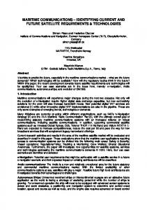
Fig. 1: Illustration of PICOSAR constellation following Sentinel-1 satellite at a safe distance.
The PICOSAR space segment consists of two compact receive-only radar satellites flying in close formation to form an along-track interferometric pair. Both satellites are flying in a safe distance to a Sentinel-1 radar satellite, which serves as a transmitter of
opportunity. This multi-static add-on approach allows the implementation of a high performing system at a very low cost. In addition to the scientific goals of PICOSAR, the mission would also serve as a technology demonstrator for several novel technologies, i.e. multi-static SAR (consolidating TanDEM-X experience and taking a first step towards multi-static configurations) and autonomous formation flying (a very tight formation is required that can only be achieved implementing operationally automated formation control).
2. Science Case and Background A major challenge for physical oceanography is to directly map the complex mesoscale and sub-mesoscale structures of surface currents in the open ocean and in the coastal regions. The global surface current field is, on one hand, highly relevant to the shipping industry and for ship route optimization. On the other hand, from a scientific perspective, it is important for atmosphere/ocean prediction and climate research through its role in the shallow overturning ocean circulation and transport of heat, nutrients, freshwater and carbon. The open ocean is mostly dominated by mesoscale flows and eddy systems, the building blocks of the ocean weather, which are found in all parts of the ocean with length scales of 10-100 km, periods of 10 days to several months and velocities of 0.1-2 m/s. Any surface-current mapping method must therefore be capable of resolving these mesoscale features and their variations in time and space in order to measure and study the characteristics of the upper ocean dynamics. In addition to this mesoscale systems, smaller sub-mesoscale processes play a crucial role in vertical mixing processes involved in the vertical transport of CO2, with its impact on climate, and, for example, nutrients. The sub-mesoscale processes are also responsible for a large share of the Total Kinetic Energy (TKE) budget. They are therefore very important for the understanding of ocean dynamics. Sub-mesoscale processes cannot be adequately observed with current EO assets. In particular, since these processes are not in geostrophic equilibrium, the associated currents cannot be derived from altimetry measurements.
3. Along-Track Interferometric (ATI) SAR The classical single-baseline ATI-SAR technique is based on the acquisition of two complex SAR images in identical geometries separated by a short time-lag, which is obtained by the usage of two separate antenna phase centers along the flight axis of a platform [1]. The estimation of the radial surface velocity field of the ocean can be obtained from the mean Doppler shift measurement, which can be based on the estimation of the phase difference between the two complex SAR images on a pixel by pixel basis. In single-baseline ATI there is a trade-off in the selection of the optimum baseline between the interferometric phase accuracy, temporal decorrelation and unambiguous velocity range. A short baseline is preferred to avoid the temporal decorrelation of the backscattered signal and to increase the range of velocities that can be estimated without ambiguity. On the other hand, a long baseline provides higher interferometric phase sensitivity. Typically, the phase estimation accuracy is improved by averaging of independent looks at the cost of a lower product resolution. It has to be
noticed that single-beam ATI provides only the radial component of the ocean surface velocity. In order to obtain the 2-D surface velocity, dual-beam interferometry (DBI) can be applied as proposed in [2]. The main idea is to employ an along-track pair of dual-beam antennas, each antenna producing a forward and an aft beam. Therefore, the radial velocity components can be obtained for both beams (i.e. both line-of-sights) from which the 2-D surface velocity can be derived [3].
4. Mission Objectives and Science Requirements The main observational objective of PICOSAR is to measure surface currents at mesoand sub-mesoscales. Ocean currents velocity and direction are the most requested variables by European oceanographers, according to a recent survey [4]. It is interesting to note that aside from ocean currents, PICOSAR measurements could also provide significant information regarding six other quantities in the top-10 list (e.g. significant wave height (SSH), wave period, wave direction spectrum, etc.). Table 1 provides a summary of the mission requirements. Unlike most other EO missions, a high resolution final product is not required. In fact, it would be even difficult to define a high resolution ocean current product, since at small scales waves dominate the surface motion. Nevertheless, the nominal resolution of the system needs to be high enough to provide a sufficient number of looks.. For global observations, the wave mode of Sentinel-1, with its characteristic 20x20 km vignettes could be adequate. Note that wider (but not longer) vignettes are achievable without any modification to S1’s operating mode. Inter-agency collaboration should make it possible to acquire larger scenes without having a significant impact on the S1 mission, which would allow the observation of full mesoscale features.
Quantity Relative velocity accuracy
Table 1: Scientific requirements. Requirement Notes 0.03 - 0.1 m/s Scientific target/minimum requirement
Ocean current velocity range
0 to 5 m/s
Spatial resolution (L2 product)
1 to 10 km
Coverage requirements
Global samples (vignettes)
Image size
20 x 20 to 100 x 100 km2
Resolution is application dependent.
Global/local monitoring.
5. Mission and Satellite Formation Concept As illustrated by fig. 1, the PICOSAR mission concept is to fly two compact satellites in very close formation at a safe distance to a Sentinel-1 (S1) spacecraft (or a similar Cband SAR satellite). The two PICOSAR satellites would carry a receive-only radar payload, allowing a very simple, light and low power instrument design. The Sentinel-1
is used as a transmitter of opportunity. PICOSAR’s mission concept is closely related to, for example, the Interferometric Cartwheel concept [5], proposed over a decade ago. The distance to the S1 satellite is uncritical, and can be in a range from 25 to 100 km, or even more. The PICOSAR satellites form an along-track interferometric pair. The along-track separation results from three considerations: • The range of ocean surface velocities considered should fit within the unambiguous velocity window. This is illustrated in Fig. 2 a), which shows the ambiguous velocity range as a function of baseline for different operating frequencies. Considering surface velocities in the -5 to +5 m/s margin, the corresponding 10 m/s unambiguous range limits the along-track separation to about 100 m. • The interferometric intrinsic sensitivity is improved with increasing baselines. • Temporal decorrelation of the ocean surface, which results in interferometric coherence loss, increases as the temporal lag due to the baseline increases.
a)
b)
Fig. 2: a) Unambiguous velocity margin as function of along-track baseline at L-, C-, X- and Ka-band; b) RMS surface velocity error as function of baseline.
The combination of these two considerations leads to an optimum baseline that will depend on the observation geometry (incident angle) and on the sea state, which is mainly driven by wind conditions. This trade-off is illustrated in Fig. 2 b), which shows the RMS error of the estimated surface velocity as a function of the baseline for different wind speeds and directions relative to the track of the spacecraft. These performance estimates show that a 100 m separation is near the optimum for high wind conditions, and results in satisfactory performance in all cases. This 100 m distance is, therefore, set as the nominal separation of the two PICOSAR spacecraft. This distance may vary significantly (e.g. ±30%) without impacting too much the mission performance. However, the baseline knowledge needs to be in the order of 1 mm. The cross-track separation between the PICOSAR satellites should stay within 20% of the along-track separation. This is small, but allows a small Helix [6,7] for safe formation flying (i.e. for some degree of passive safety, like in the case of TanDEM-X). The close formation considered requires autonomous formation flying capabilities and,
therefore, a mutual exchange of precise GPS data. The required autonomous formation flying capabilities (see table 2) have been demonstrated by the PRISMA mission.
Relative position control
Table 2: Formation requirements. S1-PICOSAR PICOSAR formation Not critical < 20 m
Relative position knowlege
Not critical
Attiude control accuracy
N/A
< 1 cm along-track < 1mm in line-of-sight 0.1°
Attiude knowledge
N/A
0.01°
6. Acquisition Modes PICOSAR operations are tied to the operating modes of Sentinel-1. PICOSAR’s mission concept is to operate primarily while Sentinel-1 operates in wave mode (WM). In this mode, 20 x 20 km2 vignettes are acquired every 100 km, alternating a 23° and a 36° incident angle. Sentinel-1 will operate in WM quasi-continuously when it flies over the oceans, so that PICOSAR would obtain global samples of the current fields.
7. Instrument Concept The architecture of the receive-only SAR instrument (see fig. 3) is a standard architecture consisting of a double-pole-double-throw (DPDT) switch, an RF down converter, an ultra-stable oscillator (USO) and a digital subsystem encompassing a timing unit, an analog-digital converter (ADC) and a field-programmable gate array (FPGA). For all of these components redundancy is required. The redundancy not only fulfills safety issues, but also enables the instrument to acquire two separate channels at the same time and thus enabling a polarimetric experimental mode. The sync-link, transmitting and receiving information about the USOs from each other’s instrument, consists of a transmit/receive unit and a digital subsystem (similar to the SAR digital subsystem). Also these components need to be redundant. The basic instrument operation concept is to keep it always running, since its power consumption is low and, in particular, this would provide thermal stability, hereby relaxing the calibration requirements. This means that the instrument is always receiving, and the control unit decides when to store data according to a maintained acquisition scheme, strongly related to the acquisition scheme of Sentinel-1. As a baseline for the SAR antenna a solid parabolic reflector with an aperture of approximately 2.0-2.5 m is assumed. The advantages of such reflectors are that they have space heritage, are generally available off-the-shelf, do not require critical mechanisms for deployment, have a high mechanical stability, and should be inexpensive. The clear disadvantage is that the size cannot be reduced (folding, etc.) and that the antenna aperture is thus the main driver for the spacecraft size, which makes the selection of a suitable launch vehicle more difficult. A first alternative could be to use cylindrical reflectors, where one dimension can be reduced without losing spatial resolution. The second alternative is to use so-called unfurlable antennas.
Fig. 3: Sketch of the SAR instrument components including the Sync Link and the interfaces to the control unit and power supply of the satellite bus. Table 3: SAR instrument technical specifications. 2.0 to 2.5 m Antenna diameter Reflector (solid or Antenna type unfurlable) Feed polarisation
H and V
Number of feeds
2
Center frequency
5.4 GHz
Receiver bandwidth
80 MHz
Signal bandwidth
48 / 75 MHz
swath / beam dependent
Sampling frequency
150 MS/s
allowing downsampling to 50 / 75 MS/s
Number of bits
8
BAQ 8:3 and/or 8:2 for data reduction
Mass budget
35 kg
including SAR antenna reflector
Power budget
50 W
to access two swathes with 23° and 36° incident angles
Although the accuracy of such antennas is absolutely sufficient for PICOSAR, they would be more expensive and introduce a higher risk, because they have to be deployed. The big advantages are, of course, the extremely compact size for the launch and the reduced weight. Some basic technical specifications of the instrument are provided in table 3.
8. Operations Concept and Data Rates The acquisitions concept has a stringent connection to Sentinel-1 acquisitions over oceans (in particular to the acquisition of wave mode vignettes, but also, in some cases, to other Sentinel-1 imaging modes, as e.g. the wide-swath mode). The acquisition plan therefore has to be maintained according to the Sentinel-1 acquisition plan, which has to be available and shall be followed. In the following it will be shown that it will not be possible to cover the worst case of maximum acquisitions with the available memory and downlink capacity. However, with an intelligent selection of the acquisitions and modes it will always be possible to reduce the data rate without a general loss of usefulness for the scientific needs. Three scenarios have been taken into account, i.e. (i) a nominal scenario with the goal to optimize for acquisitions of ocean currents, (ii) an experimental scenario with dedicated campaigns for high peak data rates dual pol acquisitions (HH/HV or VV/VH), and (iii) a minimum scenario in case of eclipse or unavailability of ground stations. For the nominal mode the following assumptions are considered for the calculation of data rates: • 12% duty cycle (Sentinel-1 transmit) • PRF: 1650 Hz • 20 km ground range (5 m resolution) • Data sampling rate: 75 MHz • On-board compression: 8:3 bit BAQ • Plus overhead/margins Table 4: Summary of data rates and volumes. Nominal single-pol Dual pol experimental mode mode (1 channel) (2 channels) 100 Mbit/s 200 Mbit/s Peak data rate (recording of vignette) 22 Mbit/s 44 Mbit/s Average data rate during instrument operation 120 Gbit not exceeding nominal mode Peak volume per orbit Rates / Volumes
Average volume per day
800 Gbit (goal)
not exceeding nominal mode
With these assumptions we can derive a peak data rate for a 23° vignette of 100 Mbit/s and a peak data rate for the 36° vignette of 80 Mbit/s, respectively. Since the incidence angles of the vignettes are alternating, the average data rate will be 22 Mbit/s, taking into account the 80 km gap between the gaps. For an orbit without ground terrain and mainly ocean, the peak volume would then sum up to about 120 Gbit. This leads to
a “theoretical” average volume per day of 1.26 TBit, which is not applicable, since it exceeds the downlink capabilities of PICOSAR. But, as mentioned before, an intelligent selection of acquisitions will be used to further reduce the data rate. Possibilities are e.g.: Areas with sea ice are only mapped occasionally; for some areas a stronger compression of 8:2 bit BAQ is applied; the mapping grid over areas of the ocean, where it is more stable, could be reduced, whereas the grid is kept at more detail in coastal areas. The goal is to acquire and downlink 800 Gbit/day. However, if necessary, this can be further reduced. The results, also for the other scenarios, are summarized in table 4.
9. Conclusions In this paper the PICOSAR mission concept for global measurements of ocean currents using two small passive – and hence cost-effective – SAR receivers has been presented. As the primary benefit PICOSAR would fill an important observational gap allowing direct measurements of ocean currents associated to sub-mesoscale processes, which cannot be observed with currently available Earth Observation assets. These submesoscale processes are the key for estimating and understanding vertical transport and mixing of CO2 (i.e. climate) and nutrients (i.e. maritime ecosystems). The predicted performance for PICOSAR clearly meets the scientific requirements. In combination with the yet clear and technologically feasible mission concept we yield a strong mission proposal. In addition DLR has leading expertise in all critical aspects of the mission, i.e. SAR, Bistatic SAR and formation flying, and the TanDEM-X heritage is certainly the key for a successful and cost-effective mission implementation. The general mission concept is not restricted to use Sentinel-1 as the transmitter, but could easily be adjusted to combine with other SAR satellites, too. A close collaboration with the Agency operating the transmitting satellite (e.g. the European Space Agency in case of S1) is practically mandatory. Exact knowledge of the transmitter system, modes and acquisitions schemes is required.
References [1] R. M. Goldstein and H. A. Zebker, “Interferometric radar measurement of ocean surface currents,” Nature, vol. 328, no. 6132, pp. 707–709, Aug. 1987. [2] S. J. Frasier and A. J. Camps, “Dual-beam interferometry for ocean surface current vector mapping,” Geoscience and Remote Sensing, IEEE Transactions on, vol. 39, no. 2, pp. 401–414, 2001. [3] J. V. Toporkov, D. Perkovic, G. Farquharson, M. A. Sletten, and S. J. Frasier, “Sea surface velocity vector retrieval using dual-beam interferometry: first demonstration,” Geoscience and Remote Sensing, IEEE Transactions on, vol. 43, no. 11, pp. 2494 – 2502, Nov. 2005. [4] N. C. Flemming, Operational Oceanography: Implementation at the European and Regional Scales : Proceedings of the Second International Conference on EuroGOOS, 11-13 March, 1999, Rome, Italy. Elsevier, 2002. [5] D. Massonnet, “Capabilities and limitations of the interferometric cartwheel,” IEEE Trans. Geosci. Remote Sensing, vol. 39, no. 3, pp. 506–520, Mar. 2001. [6] A. Moreira, G. Krieger, and J. Mittermayer, “Satellite configuration for interferometric and/or tomographic remote ...,” U.S. Patent 667788413-Jan-2004. [7] S. D’Amico and O. Montenbruck, “Proximity Operations of Formation-Flying Spacecraft Using an Eccentricity/Inclination Vector Separation,” Journal of Guidance Control and Dynamics, vol. 29, no. 3, pp. 554–563, 2006.