PID and Fuzzy Logic Optimized Control for Temperature in Infant Incubators Abdel Rahman Shabaan, Shereen M. El-Metwally, Moustafa M.A. Farghaly, Amr A. Sharawi
Abstract— This paper presents the design and implementation of a real-time system for the temperature monitoring and control in an infant incubator using a PIC16F877 microcontroller. The implementation of a set of control approaches on the microcontroller is investigated: direct on-off control, proportional (P-control), proportional-integral (PI-control), proportional-integral-derivative (PID-control) and fuzzy logic control. The temperature is measured using reusable skin/surface probe sensor. The controller output determines the amount of power supplied to the heater by employing pulse width modulation and a triac-triggered circuit. The performance of the applied control approaches is evaluated and compared. It was concluded that the fuzzy logic controller resulted in the most accurate response with the least settling time and standard deviation compared with the other approaches. Index Terms— PID-control, fuzzy logic, temperature
control, PIC16F877, infant incubator. I. INTRODUCTION Premature birth is a one of the major problems nowadays all over the world. About two hundred thousand infants are born prematurely out of 2.4 millions every year in Egypt, which is about 8.3 percent [1]. The risks of complications increase with the decrease of the term of pregnancy. The risk of death increases in the first few weeks of premature delivery. Premature babies and other high risk infants do not have the ability to regulate temperature and produce heat, because they don't have a fully developed thermal regulatory center, as a result of prematurity [2]. They have a large surface area to volume ratio and very low metabolic rate [3]-[6]. As a result, a higher heat loss from the skin occurs without the ability of producing enough heat. The chances of survival for these premature babies are very low in the first few weeks of their lives; from this point thermo regulation of the media around premature infants in infant incubators is a major factor to be considered [7], [8]. The core temperature of Abdel Rahman Shabaan is with the Department of Systems and Biomedical, Shorouk Higher institute of Engineering, EL-Shorouk, Egypt and with the Department of Systems and Biomedical Engineering, Cairo University, Giza, Egypt (corresponding author: +02-0100-7745988; e-mail:
[email protected]). Shereen M. El-Metwally is with the Department of Systems and Biomedical Engineering, Cairo University, Giza, Egypt (e-mail:
[email protected]). Moustafa M.A. Farghaly is with the Department of Systems and Biomedical, Shorouk Higher institute of Engineering, EL-Shorouk, Egypt (e-mail:
[email protected]). Amr A. Sharawi is with the Department of Systems and Biomedical Engineering, Cairo University, Giza, Egypt (e-mail:
[email protected]). .
the human body needs to be kept at a constant temperature of 37ºc. Variations in temperature can result in organ damage, illness, or in some cases death. Neurological damage can be a result of slight to significant increase in brain temperature [9]. The temperature controlling process is affected by many factors. These factors may depend on infant-related parameters or incubator-related parameters [10]. Infant-related parameters depend on variables such as size, maturity level, metabolic factor, etc. The smaller the size of the infant, the more care he needs. The incubator-related parameters include incubator size, wall thickness, mattress material, incubator heating type (convective heating), and control mechanisms. The temperature control mechanism is the main and most important parameter. Different mechanisms mainly employ either the infant skin temperature or the incubator air temperature. New incubator designs allow the user to choose between the air control and the skin control [11]. Most previous studies make a model for infant incubators and use direct on-off control approach [12], [13]. This method is the easiest feedback control mechanism but it shows large fluctuations in temperature. In [12], PID control resulted in a decreased fluctuation of air temperature but the tuning of its parameters needs much effort. In [13], fuzzy logic control was used with skin temperature and air temperature as inputs and its output controls the heater driver circuit in order to reduce fluctuations in air and skin temperature. Fuzzy logic control is one of the best decision making techniques. The reason fuzzy logic is applied in this work is that it helps in making decision in case it is difficult to tune the system without its modeling. In this paper, a set of control approaches is implemented on a PIC16F877 microcontroller as a standalone system for the temperature control inside infant incubators. The temperature is acquired using infant skin sensors. The paper is organized as follows. First, an explanation of the temperature control circuit employed including sensors, microcontroller, and the heater circuit is given. Second, the applied feedback control systems including on-off, P-control, PI-control, PID-control and fuzzy logic are described. A comparison between the performances of the various applied controllers is then presented. II. MATERIALS AND METHODS
A. The temperature Control System The incubator is provided with a motor and a fan that sucks the air through it, the air then passes through a 400W-heater resistance. A temperature sensor measures the actual air
temperature inside the incubator chamber. A measurement amplifier circuit takes the output of sensor, amplifies it then delivers it to the microcontroller that to begin the control process. The output of the microcontroller controls the power of the heater by pulse width modulation and a triac triggering circuit. The block diagram of the whole system is shown in figure 1. The details of the circuitry are listed below [14].
Integral control is almost always used with proportional control. Proportional integral control eliminates forced oscillations and steady state error resulting from the on-off control and P-control actions, respectively. The control signal resulting from the proportional integral controller is given by:
A.1 Input layer The circuitry of the input layer is shown in figure 2. It consists of a 427 (Measurement Specialties, Inc.) reusable skin/ surface probe temperature sensor and a measurement amplifier. The sensor relation between the output voltage and measured temperature is
where Ti is the integral time constant of proportional integral controller and e(t) is the error signal. In a discretized form, the control signal is given by:
(
) (1)
A.2 Microcontroller A PIC16F877 is used to monitor and control the temperature. The analog temperature signal is read from the on-chip analog to digital converter port pin (A.0). The resolution of the converted digital word is 10bits. The digital temperature value is processed using the implemented control mechanism in order to control the duty cycle of the heater ac supply by using pulse width modulation. The microcontroller output is sent through the port pin (C.0).The microcontroller pin connections are illustrated in figure 3. An LCD screen (2x16) connected to the microcontroller to set and display the desired and actual temperature. A.3 Heater driver The microcontroller output is applied to an NPN transistor. The transistor supplies sufficient current to a solid state relay which adjusts the power of the heater in accordance to the pulse width of the triggering signal. The heater driver circuit is illustrated in figure 4. B. The Control Process B.1 On-off controller The on-off control action is illustrated in figure 5. The heating power is either fully on when the temperature inside the incubator is below the set point or fully off when it is above it. As a result the temperature oscillates about the set point. B.2 Proportional control Proportional control is the one of the simplest feedback control to implement, and the most common kind of control loop [15]. In proportional control, the error signal is just multiplied by a constant gain and fed out to the driver. The controller output is calculated according to the following equations: ( ) (2) ( ) ( ) (3) Where e(k) is the error signal, u(k) is the output of the controller, and kp is the proportional gain. B.3 Proportional integral control (PI)
()
* ()
( )
(∫ ( )
( )
)+
∑
(4)
( )
(5)
where kp and ki are the proportional and integral gains, respectively. B.4 Proportional integral derivative control (PID) The derivative part of the PID controller is proportional to the prognosis of error signal at time t + Td where Td is the derivative time constant of the controller [15],[16]. The control signal of the PID controller is given by: ()
* ()
∫ (
()
)
+
(6)
Or, the output of the controller can be written as: ()
()
*∫ (
)
+
()
(7)
where kp, ki and kd represent the proportional, integral and derivative gains, respectively. B.4.1 Discretized PID Controllers Taking the Laplace transform of equation (6): ( )
(
*
( )
)+
(8)
In order to discretize the PID controller, the backward difference transformation was chosen as the method of approximation. This gives the relationship between s and Z: (9) where Ts is the sampling time. By substituting this in equation (7 )then taking the ztransform, we obtain: ( )
[
(
)
(
)] ( )
(10)
By taking the inverse z-transform, the control output is given by: ( ) (
( )
∑
( )
( ( )
)) (11)
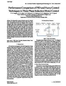
B.5 Parameter tuning according to Ziegler-Nichols recommendations Ziegler and Nichols recommendations describe simple mathematical procedures for tuning PID controllers. Ziegler-Nichols formulae for specifying the controllers are based on plant step responses. The first method is applied to plants with step responses of the form displayed in figure 6. This type of response is typical of a first order system with transportation delay. The two parameters characterizing the response are: L, the delay time, and T, the time constant. T and L are found by noting the intersection between the time axis and the steady state value of the tangent to the step response at its point of origin [17], [18]. The Ziegler-Nichols recipe for the parameters tuning is given in Table I. B.6 Fuzzy Logic Control The implemented fuzzy logic system incorporates both the error (e) and the change of the error (∆e) to control the power supply to the heater; there by control the temperature of hot air flow into the incubator. The error as well as the change of error were calculated and used as inputs to the fuzzy logic system. The implementation process of the fuzzy logic control involved many steps. The very first step was to convert the crisp values of input parameters (℮ and ∆℮) into a set of fuzzy variables. Membership values for the fuzzy sets were obtained using the membership functions. A set of fuzzy rules were defined depending on the needs of the system [19], [20]. The membership values were then input to the rule based system (look up table III). These rules decide the fuzzy output based on the fuzzy input variables. After the fuzzy output was attained a centroid defuzzifier was used to convert the fuzzy output into the crisp output [20]. The block diagram in Figure 7 illustrates the procedure. The system has 2 inputs and 1 output. B.6.1 Inputs: 1) Error (e): is calculated by subtracting the actual air temperature measured using a probe placed in the incubator from the desired temperature. 2) Change in error (∆e): It provides additional information on whether the temperature is increasing, decreasing or stable, therefore, further enhances the ability of the controller to control the temperature. This change in error is derived by taking the derivative of the error in temperature with respect to time. B.6.2 Output: The power of the heater is the output variable. It is controlled by ratio of the time the heater is on with respect to the sum of the time the heater is on and off. Therefore, the output is varied from a minimum value of zero to a maximum value of one. B.6.3 Fuzzy subsets and membership functions: Fuzzy subsets are different from the crisp sets defined in classical theories. For crisp sets, the value of a parameter does or does not belong to a subset. However, for the fuzzy sets, a parameter can partially belong to two subsets at the same time. A fuzzy set is completely characterized by its
membership function (MF). Due to their simple formulas and computational efficiency, both triangular and trapezoidal MFs have been used extensively, especially in real-time implementations [2]. Fuzzy subsets were defined for the two input variables: error, change in error, and the output power of the heater. The domains of the input and output variables were divided into four subsets and correspondingly four membership functions were formed. These domains are specified as follows: 1) Error: very close, close, far, very far. 2) Change in error: very slow, slow, fast, very fast. 3) Heater power: very light, light, heavy, very heavy. The crisp input and output variables were fuzzified by converting it into membership values corresponding to the four subsets. Membership values actually define the extent to which a variable belongs to a subset. A combination of triangular and trapezoidal functions was used. Table II shows the membership functions used for the various subsets of the input error and change in error. The Membership functions for the error, change of error, and output power are figure 8, 9 and 10, respectively. B.6.4 Fuzzy Rules: The fuzzy system rules were obtained by examining the different possibilities that could occur from the combinations of ℮ and ∆℮ adjectives as given in Table III. The fuzzy rules manipulate the value of power depending on actual ℮ and ∆℮ values. For example, if the ℮ is close and ∆℮ is slow, power should be very heavy. System tuning was done so that for the various values of the error and the change of error, the corresponding fuzzy rules give the output power required to keep air temperature inside the incubator constant at the desired temperature. B.6.5 The Controller’s defuzzification interface: The commonly used defuzzification method called the Centre of Gravity (COG) is used to compute the crisp value of the controller’s output. The COG defuzzification is determined by: ∑
(12)
∑
Where Rj represents the centroid of domain j, and represents the output membership value for the domain j. III. RESULTS AND DISCUSSION
A. Direct on-off control Figure 11 shows the temperature time response using the direct on-off control algorithm for a desired temperature of 35 °C The control input is equal to 100 percent of power when the temperature inside the incubator is below the set point, and when temperature above set point it is OFF. As seen from figure 11, the temperature exhibits large oscillations around the desired set point within ±0.4 °c.
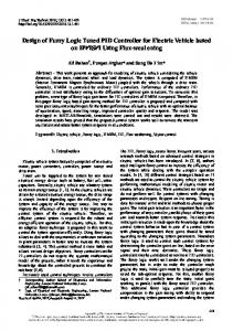
B. Stabilization on-off controllers The Ziegler-Nichols method was applied to adjust the parameters of PID control. Using this method, it was found that T=160 sec and L=8 sec. The parameters kp, Ti and Td are given in table IV. B.1 Response using Proportional controller Using Zeigler-Nichols tuning method, kp was set to 20. Figure 12 shows the actual temperature versus time using pure proportional feedback control for different values of kp. It can be seen that as kp increases, the system becomes faster and closer to the desired set point. At kp = 20, the steady state error is 0.6°c. B.2 Response using Proportional Integral controller (PI) Using Ziegler-Nichols tuning rule, kp and ki are set to 18 and 0.65, respectively figure 13 shows the resulting temperature time response for different values of kp and ki. For kp = 18 and ki = 0.65, it can be seen that the steady state error decreases to 0.042 and the settling time is approximately 18.8 minutes and the overshoot is approximately 0.28%. B.3 Response using Proportional Integral Derivative controller (PID) Using Ziegler-Nichols tuning rule, the controller parameters are set as follows: kp = 24, ki = 1.45 and kd = 99.Figure 14 shows the obtained temperature time response using the PID controller. It can be seen that the settling time is about 14.6 minute which is less than the settling time using the PI controller. However, it results in an overshoot of approximately 1.14% but it will not appreciably affect the performance in steady state. C. Fuzzy logic control Figure 15 shows the resulting temperature time response using fuzzy control on the heater system. It can be seen that the steady state error decreases to 0.0168 and the settling time is approximately 7.8 minutes with no overshoot.
most accurate response, showing no overshoot. Table V shows a comparison of the measured parameters for the temperature time responses obtained using the various controllers. From table V it can be deduced that the on-off and P- control are not accepted due to the very high oscillatory response for the direct on-off control and the over-damped response obtained using the P-control. The fuzzy logic control resulted in the temperature time response with the smallest deviation, no overshoot, and the least settling time in comparison to the PI and PID controllers. IV. CONCLUSION
The goal of this paper was to develop a microcontroller-based temperature controller for infant incubators. A set of control approaches were implemented on a PIC16F877 microcontroller and their performances were compared. The presented design could provide an optimum automatic control of temperature using the fuzzy logic control approach with the error and change in error in temperature as inputs and the power of the heater as output. The fuzzy logic control was shown to result in the temperature time response with the highest accuracy and smallest settling time compared to the other controllers' responses. REFERENCES [1] [2]
[3]
[4]
[5]
[6] [7] [8]
D. Controllers' performance evaluation A set of parameters are measured in order to evaluate the obtained temperature time responses using the various controllers. 1) Standard deviation: is the deviation of the measured temperature values from the mean temperature. 2) Overshoot: is the magnitude by which the measured temperature 'swings' past the set point. 3) Settling time: is the time taken by the process output to stay within +/- 0.5% of set point. 4) Rising time: is the time taken by the response to reach desired temperature. Figure 16 shows the temperature time responses using the various controllers: P, PI, PID and fuzzy logic controllers. It can be deduced that the fuzzy logic controller resulted in the
[9]
[10]
[11] [12]
[13]
[14]
http://www.capmas.gov.eg/ P.H Perlstein, H. Atherton, ―Infant incubators,‖ in Encyclopedia of Medical Devices, J.G. Webster, Ed. NY: Wiley, 1988, pp. 1643- 1656. K. Brück, ―Heat production and temperature regulation,‖ in Perinatal Physiology, U. Stave, Ed. New York: Plenum, 1978, pp. 455–498. M. H. LeBlanc, ―The physics of thermal exchange between infants and their environment,‖ Med. Instrum, vol. 21, no. 1, pp. 11-5, Feb. 1987. P. H. Perlstein, ―Physical environment,‖ in Neonatal-perinatal medicine: diseases of the fetus and infant, 6th ed. vol. 1, A. A. Fanaroff, R. J. Martin, Eds. St Louis : Mosby, 1997, pp. 259-277. Garima Mathur, ―Fuzzy logic control for infant incubator system,‖ M.Sc dissertation, University of Akron, August 2006. V. Hurgoiu, ―Thermal regulation in preterm infant,‖ Early Hum Dev., vol. 28, no. 1, pp. 1-5, Jan. 1992. K. A. Thomas, ―Preterm infant thermal responses due to care giving differ by incubator control mode,‖J Perinatol, vol. 23, no. 8, pp. 640-5, Dec 2003. G. Simbruner, E. M. Ruttner, A. Schulz, and K. Perzlmaier, ―Premature infants are less capable of maintaining thermal balance of head and body with increases of thermal environment than with decreases,‖ Am J Perinatol, vol. 22, no. 1, pp. 25-33, Jan. 2005. K.A Thomas, R. Burr, ―Preterm infant thermal care: differing thermal environments produced by air versus skin servo-control incubators,‖ J Perinatol, vol. 19, no. 4, pp. 264-70, Jun 1999. K. H. Marks, ―Incubators,‖ Med. Instrum, vol. 21, no. 1, pp. 259– 277, 1987. Med Aymen Zermani, Elyes Feki and Abdelkader Mami, ― Application of Adaptive Predictive Control to a Newborn Incubator,‖ American J. of Engineering and Applied Sciences, vol. 4, no. 2, pp. 235-243, ISSN 1941-702, 2011. Narender P. Reddy, ― Toward a Fuzzy Logic Control of the Infant Incubator,‖ Annals of Biomedical Engineering, vol. 37, no. 10, pp. 2146–2152, Oct. 2009. Aritra De, ―Water temperature controller using microcontroller and correction using fuzzy logic,‖ International Journal of Emerging Technology and Advanced Engineering, ISSN 2250-
2459, vol. 2, no. 6, June 2012. [15] Ioan D. Landau and Gianluca Zito, Digital Control Systems Design Identification and Implementation. Springer, 2006, pp. 57-166. [16] B.V Sreenivasappa, ―Analysis and implementation of discrete time PID controllers using FPGA,‖ International Journal of Electrical and Computer Engineering, ISSN 0974-2190, vol. 2, pp. 71—82, 2010. [17] J.G Ziegler, N.B Nichols, ―Optimum settings for automatic controllers,‖ Transactions of the A.S.M.E., vol. 64, pp. 759-768, 1942. [18] Payam Solatian, ―Simulation Study of Flow Control Based On PID ANFIS Controller for Non-Linear Process Plants,‖ American Journal of Intelligent Systems, p-ISSN: 2165-8978, e-ISSN: 2165-8994, 2012. [19] A. Das, N. P. Reddy, and J. Narayanan, ―Hybrid fuzzy logic committee neural networks for recognition of swallowing acceleration signals,‖ Compute. Methods Programs Biomed, vol. 64, no. 2, pp. 87-99, Feb. 2001. [20] S. Suryanarayanan, N. P. Reddy, and E. P. Canilang, ―A fuzzy logic diagnosis system for classification of pharyngeal dysphagia,‖ Int J Biomed Comput., vol. 38, no. 3, pp. 207-15, Mar 1995. [21] White, ―Infant incubators,‖ in Encyclopedia of Medical Devices, edited by J. G. Webster, Ed. NY: Wiley, 2006, pp. 114–157.
Fig. 4. Heater driver circuit.
Fig. 5. On-off control action.
Fig. 1. Block diagram of microcontroller-based temperature control system Fig. 6. Response curve for Ziegler-Nichols method. Table I: Ziegler-Nichols recipe: First method PID Kp Ti=Kp/Ki Td=Kd/Kp P T/L ∞ 0
Fig. 2. Temperature sensor and measurement amplifier.
Fig. 3. PIC16F877 pin connections and LCD drive circuit.
PI
0.9*T/L
L/0.3
0
PID
1.2*T/L
2L
0.5L
Fig. 9. Membership functions for change of error
Fig. 7. Flow chart of fuzzy logic control system. Table II: Membership functions of the error and change in error subsets Fuzzy subset Equation Very slow ( ) { Slow
Fast
Very fast
very close Close
Far
)
{
(
( ( )
{
( )
{
( )
{
((
)
(
)
((
( )
) (( (
{ {
)
)
((
( )
Fig. 10. Membership functions for power of heater.
)
{
( )
)
((
)
) )
)
Table III : Fuzzy rules ∆℮ very low ℮
low
fast
very fast
very close
very heavy very heavy very heavy
very heavy
close
Heavy
very heavy very heavy
very heavy
far
light
Heavy
very heavy
very heavy
very far
very light
Light
heavy
very heavy
0
20
30 40 50 Time (min)
) (
) )
36
)
Temperature °C
Very Far
(
( )
34 32 30 28 26 24
Fig. 8. Membership functions for error.
10
60
70
Fig. 11. Temperature time response using direct on-off control algorithm
Table IV: Parameters using Ziegler-Nichols Kp 20
Ti=Kp/Ki ∞
Td=Kd/Kp 0
37
PI
18
27.6
0
35
PID
24
16.5
4.125
Temperature(°C)
PID P
Temperature (°C)
37 35 33
33 31 29 27 25
31
KP=10
29
KP=15
27
KP=20
0
10
20
30 40 Time(min)
60
70
Fig. 15. Temperature time response using fuzzy logic control.
36
25 0
20
40
60
80
35 Temperature (°C)
Time (min) Fig. 12. Temperature time response using P control
37
Temperature (°C)
35 33
34 33 32 31
31
Kp=18,Ki=0.65
29
kp=9.8,Ki=0.1
27
kp=12,ki=0.1
2
20
40 Time (min)
42 Time (min)
Rising time (min)
60
on-off control P-control
Fig. 13. Temperature time response using PI controller.
Overshoot (%) 1%
Over damped
PI control PID control Fuzzy logic
35
30
25 0
10
20
30 40 Time (min)
50
60
Fig. 14. Temperature time response using the PID controller.
62
Fig. 16. the temperature time responses using the various controllers: P, PI, PID and fuzzy logic controllers.
23 0
22
Table V : Summary of the performance of the closed-loop systems for the on-off, P, PI, PID and fuzzy logic controllers.
25
Temperature(°C)
50
70
No overshoot
Standard deviation
Settling time (min)