PID and State Feedback Control of a Single-Link Flexible Joint Robot Manipulator İsmail H. AKYUZ†, Ersin YOLACAN†, H. Metin ERTUNC† and Zafer BINGUL† †
Department of Mechatronics Engineering Kocaeli University, Kocaeli, TURKEY
[email protected],
[email protected],
[email protected],
[email protected] Abstract – In this work, a single – link flexible joint robot manipulator is constructed and controlled using various control techniques. The position and trajectory control is performed by PID and State Feedback control methods for this system. The purpose of this study is to keep the rotate angle of the link at desired position and to eliminate the oscillation angle of end effectors. The experimental results were compared for each method. The control blocks required for the system are performed on Matlab – SIMULINK and applied dSpace 1103 control board. The experimental results of the system based on PID and State Feedback controller are quite satisfactory. Key Words: PID control, State Feedback Control, Single – Link Flexible Joint Manipulator
I. INTRODUCTION In modern robot systems, flexibility has become very important due to satisfying special needs of industrial automation. To date, control engineers have been working on the development of a mathematical model and control of flexible structures. Flexible mechanisms and flexible joint manipulators are usually used in servicing sector, various space station building and maintenance, gantry cranes, atomic force microscopes, medical and defense industries [1]. Generally, flexibility is an undesirable feature in robot manipulators because of causing significant control problems such as vibration and static deflection. These control problems emerge from external effects, designing errors and nonlinear dynamic behavior of flexible materials. The nonlinear vibrations decrease the end-point accuracy, increase settling time and make the controller design scheme be complicated. However, special purpose robot manipulators have been currently designed with flexible links which offer the following benefits: increased payload capacity (greater the ratio of payload weight to robot weight), reduced energy consumption (use of less powerful actuators), cheaper construction (fewer materials and smaller actuators), faster movements (higher accelerations because of lighter links), longer reach (more access and space because of a more slender construction) and safer operation (no damage because of the compliance and low inertia). According to a survey about flexible structures [2], the control algorithms developed for existing flexible systems have various limitations for precision and accuracy. But these features of the controllers could be improved using different control structures.
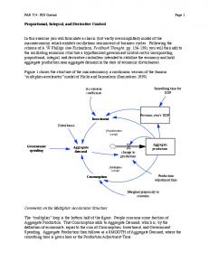
There exist two different control approaches to control flexible link mechanisms in the literature: i) Linear control, ii) Nonlinear control methods. Applied linear control methods developed for flexible robot manipulators are: linear quadratic regulator (LQG) [3], H∞ control algorithms [4], PID control methods [5] and state feedback control [6]. It is quite difficult to control flexible mechanisms with conventional linear control methods due to nonlinear dynamics of flexible structures. Applied nonlinear control methods in the literature are as follows: adaptive control schemes such as adaptive neuro fuzzy inference system (ANFIS) [7], fuzzy model reference learning control method (FMRLC) [8], sliding mode control methods [9], hybrid actuator scheme with sliding mode controller [10], adaptive nonlinear boundary control [11], and PI – PD – PID like fuzzy logic controllers [12]. In this study, vibration control and trajectory tracking control of a flexible robot arm with PID and State Feedback Control are developed and the flexible system is produced for research purposes. II. MODELING OF SINGLE - LINK FLEXIBLE JOINT MANIPULATOR A. Mathematical Model A mathematical model for single joint flexible manipulator can be obtained easily from Lagrange equations [13,14]. As shown Fig. 1, the system has two degree of freedoms and the joint which is mounted to the shaft moves according to rotate direction of the motor. In the Fig. 1, θ is rotate angle and α is oscillation angle of end effectors.
Fig. 1. Structure of single – link flexible joint manipulator.
The values and symbols of system parameters are summarized in Table 1. TABLE I SYMBOL Jlink Rm Kg Km Ks M G H Jh
PARAMETERS OF FLEXIBLE J OINT ROBOT M ANIPULATOR DESCRITION VALUE Inertia of flexible manipulator 0.003882 kgm2 Motor resistance 15.5 Ω Gear ratio of reductor 1/36 Motor constant 0.0089 N/(rad/sn) Flexibility coefficient of joint 5.468 N/m Mass of the flexible joint 0.03235 kg Gravitational acceleration -9.81 N/m Distance to center of gravity of rotational platform of flexible 0.06 m manipulator
Consequently, the system can be expressed in the following equations: x1 x3 x2 x4 2
x3
h
l
2
(8)
2
K K K K Ks K mgh x2 m g x3 m g s x2 Jh Rm J h Rm J h Jl Jl
where the system input is u V , outputs are the rotate angle of flexible joint (θ) and deflection angle of end effectors (α). As shown, system has two outputs y x1 x2 ( x1 and x 2 ). In this case, state space model of the system can be given as follows: x f x g x u y x1 x2
(2)
x3 x 4 2 2 (9) Km K g Ks x2 x3 f x Jh Rm J h 2 2 K Km K g Ks mgh s x2 x2 x3 sin x1 x2 Jl Rm J h Jl Jh 0 0 KmKg g x R J m h Km K g R J m h
(3)
1
where τ is the motor torque. As known, the torque is obtained by the voltage that is applied to armature. In this study, the voltage ‘V’ is determined as system input. Also the relationship between torque and voltage can be expressed as follows: iRm K m K g
2
K K K K Ks x2 m g x3 m g Jh Rm J h Rm J h
x4
The system can be expressed as follows for basic motion; J l J l K s mgh sin( ) 0 J J J mgh sin( )
(7)
3
(1)
L L 0 L L
(6)
x4
where, K and P are kinetic and potential energy of the system, respectively. The Lagrange motion equations are given as follows; d dt d dt
K 2m K 2 g Rm
x1 x2 x
The system can be expressed by energy based Lagrange method. The Lagrangian equation is computed from kinetic and potential energy; L K P
Rm
In this study, the state variables are determined as follows:
0.00035 kgm 2
Inertia of rotational platform
KmK g
(4)
B. System Design and Development of the Solid the Solid Model
where ω is angular velocity of motor, i is armature current, Rm is motor resistance, Km and Kg is the motor parameters. Furthermore;
The solid model of the real system designed in Solid Works® shown in Fig. 2. In addition material specifications of the single – link flexible joint robot manipulator are given in the following list.
Km K g i Rm Rm
i
K g Km
(5)
Thus the relationship between torque and voltage can be rewritten as:
2.5 mm rotating platform from galvanized sheet, 3 mm upper cover from aluminum sheet, Spring mounting part from stainless steel, 16 mm optical encoder bush and 7 mm diameter stainless steel material.
Moreover except from this detail, total weight of this mechanical model is 1435.6 gr. On the other hand, the joint length of the model is 400 mm and it can be extended to 580 mm. Thus, different experiments can be developed for various links.
Moreover, Simulink real time control blocks are analyzed for dSpace Ds1103 controller board. A. PID Control PID (Proportional – Integral - Derivative) control is one of the classical control methods that is frequently used nowadays especially on industry because of simple structure and working stable. PID control block scheme is shown in Fig. 4.
Fig. 4. PID Control block scheme Fig. 2. Solid model of single – link flexible joint robot manipulator
The physical model of flexible manipulator which is produced according to Fig. 2 is shown in Fig. 3
PID algorithm is used to compute the control signal that activates the real system based on the following formula. u (t ) K p e(t ) K I e(t )dt K D
d e(t ) dt
(10) (11)
e(t ) r (t ) y (t )
where u(t) is control parameter, e(t) is error and y(t) is output parameter. Furthermore K p , K D and K i are PID parameters which need to be tuned. In this method, e(t) is the error variable that is reduced to zero upon parameter tune. Thus the system response is adjusted to desired reference. As shown from equation (10), u(t) control signal is consist of three sums. The first one is product of e(t) error signal by K p , proportional gain, and the second one is the product of K i integral gain by integral of e(t), finally the last one is product of K D , derivative gain, and derivative of e(t). In general the effects of K p ,
K D and K i PID parameters on system
response is shown in Table 2. Fig. 3. Physical model of single – link flexible joint robot manipulator
III. CONTROLLER DESIGN FOR F LEXIBLE JOINT ROBOT MANIPULATOR In this section, PID and State Feedback controllers are designed for single-link flexible joint robot manipulator.
Kp KD Ki
TABLE II EFFECT OF PID P ARAMETERS ON SYSTEM RESPONSE Rise Time Overshoot Settling Steady Time State Error Reduce Increase Small Reduce Change Reduce Increase Increase Eleminate Small Change
Reduce
Reduce
Small Change
Main scheme of PID control for this study is illustrated in Fig. 5. As shown in Fig. 5, the controller scheme includes four blocks: measurement block, input block, controller block and output block.
IV. EXPERIMENTAL RESULTS AND COMPARISION In this study, trajectory tracking for sinus – kane functions and step response experiments are performed for PID control and state feedback control. The test results are given in Figs. 8 -10 for the PID control.
Fig. 5.Main block of PID control for single joint flexible robot manipulator
B. State Feedback Control The state feedback control is considered as the basis of modern control techniques [15]. In this control method, state variables are multiplied by definite gain values and feedback to sum node. State feedback control method is frequently used on position control application in industry. The block scheme of the state feedback control is shown in Fig. 6.
Fig. 8. Sinus trajectory tracking of flexible manipulator
As seen Fig. 8, theta angle is tracking the reference signal as desired. Since there is smooth change on the sinus signal, PID controller response is satisfactory. Besides the alpha angle has small oscillation around the zero. The oscillation is between -1.8° and +1.8°.
Fig. 6. Block diagram of state feedback control
where r(t) is reference input, u(t) is comparator output signal, x(t) is state variable and y(t) is output variable. Moreover, K is feedback vector and C is defined matrix for coefficients. In this method there are two main problems: (1) Impossibility of measurement of all states and (2) sensor necessity for all states. This necessity is a factor that increases the system cost. Both to decrease the cost and to obtain the immeasurable state data, it should be designed an observer. State feedback controller block for this study is shown in Fig. 7.
Fig. 7.State feedback control main block of single link flexible joint manipulator
Fig.9. Step response of both flexible link and end effecter
The step response of both theta and alpha angle are given are given in Fig. 9. As seen from the figure, theta angle is tracking to desired reference. However, there is an overshoot occur due to instantaneous changing of the step function. At the changing time, derivation has big value and this cause an overshoot on the system.
Fig. 10. Kane trajectory tracking of flexible link
Fig.12. Sinus trajectory tracking of flexible manipulator of State feedback control
In Fig. 10, the kane trajectory response is given. Despite there is small deflection, theta angel response is satisfactory for this control method. As seen that, alpha angel has more oscillation than sinus trajectory tracking at first. However, oscillation is eliminated by the controller.
As seen Fig. 12, theta angle is tracking the reference signal as desired. Since there is smooth change on the sinus signal, the state feedback controller response is satisfactory. Besides the alpha angle has small oscillation around the zero. The oscillation is between -1° and +1°. We obtained better trajectory tracking response than PID Control.
As seen from the experimental results, the performance of PID controller applied in this study is quite satisfactory. Despite there is occur small deflections, oscillations and overshoot theta and alpha angles are stabilized to desired reference. The test results are given in Figs. 11 -13 for the state feedback control.
Fig.13. Kane trajectory tracking of flexible link of State feedback control
The kane trajectory response of state feedback control is given in Fig. 13. Despite there is small overshoot in theta angle and small oscillation in alpha angle, both theta and alpha angles are stabilized to desired reference. V. CONCLUSIONS Fig.11. Step response of both flexible link and end effector of State feedback control
As seen Fig.11, through theta angle is tracking to desired reference, the alpha angle has oscillations. Just as in the case of PID control, there is an overshoot occur due to instantaneous changing of the step function. In this control method, the overshoots and oscillations of both flexible link and end effecter are more than that of PID method.
In this study, PID and State feedback control methods have been studied for Single - Link Flexible Joint Robot Manipulator. The obtained results are compared due to various input signals for each control methods. Despite PID and state feedback control responses are similarly, each control methods have advantages and disadvantages. It can be seen easily from the experimental results, step responses of PID control method are more satisfactory than the state feedback control. Because of step and kane trajectory responses of the state feedback control method have more overshoot and oscillation. The
results show that state feedback control slightly outperforms the PID control for single-link flexible manipulator. REFERENCES [1] [2]
[3]
[4]
[5]
[6]
[7]
[8]
[9]
[10]
[11]
[12]
[13] [14] [15]
Passino K., and Yurkovich S., “Fuzzy Control”, Addison-Wesley Publishing Company, 1998. Book, W.J., “Modeling, design and control of flexible link manipulator arms: a tutorial review”, Proceedings of IEEE Conference on Decision and Control. 500-506, 1990. Cannon R.H., Schmitz E.,Jr., “Initial experiments on the end-point control of a flexible one-link robot”, International Journal of Robotics Research 3, 62-75, 1984 Trautman C., Wang D., “Experimental control of a single flexible link with a shoulder joint”, IEEE International Conference On Robotic and Automation 1, 1235-1241, 1995. Tzu Ho M., Wei Tu Y., “PID Controller Design for a FlexibleLink Manipulator”, 44th IEEE Conference on Decision and Control, and European Control Conference, 6841-6846, 2005. Tien L.L., Schaffer A.A., Hirzinger G., “MIMO State Feedback Controller for a Flexible Joint Robot with Strong Joint Coupling”, IEEE International Conference on Robotics and Automation, 3824-3830, 2007. Jang J.-S.R., “ANFIS: Adaptive-Network-based fuzzy inference systems”, IEEE Transactions on Systems, Man and Cybernetics 23, 665-685, 1993. Passino K.M., Yurkovich S., “Fuzzy Learning Control for a Flexible-Link Robot”, IEEE Transactions on Fuzzy Systems 3, 199-210, 1995. Kitamura Y., Iwabuchi K., Nonami K., Nishimura H., “Positioning control of flexible arm using frequency-shaped sliding mode control”, Third International Conference on Motion and Vibration Control, 178-183, 1996. Choi S.B., Shin H.C., “A hybrid actuator scheme for robust position control of a flexible single-link manipulator”, Journal of Robotic Systems 13, 359-370, 1996. De Querrioz M., Dawson D., Agarwal M. And Zhang F., “Adaptive nonlinear boundary control of a flexible link robot arm”, IEEE International Transactions on Robotics and Automation 15, 779-787, 1999. Siddique M.N.H., Tokhi M.O., “GA-based Neural Fuzzy Control of Flexible-link Manipulators”, Journal of Engineering Letters 13, 2006. http://www.quanser.com (Access date:1.8.2010) http://www.ece.osu.edu/~passino/lab5prelabnlc.pdf (Access date:1.8.2010) Kuo B.C., “Automatically Control Systems”, Prentice-Hall, Inc. A Simon &Schuster Company.