Email: {kumm,zipf}@uni-kassel.de. AbstractâCompressor trees offer an effective realization of the multiple input addition needed by many arithmetic operations.
Pipelined Compressor Tree Optimization using Integer Linear Programming Martin Kumm and Peter Zipf University of Kassel, Germany Digital Technology Group Email: {kumm,zipf}@uni-kassel.de
Abstract—Compressor trees offer an effective realization of the multiple input addition needed by many arithmetic operations. However, mapping the commonly used carry save adders (CSA) of classical compressor trees to FPGAs suffers from a poor resource utilization. This can be enhanced by using generalized performance counters (GPCs). Prior work has shown that high efficient GPCs can be constructed by exploiting the low-level structure of the FPGA. However, due to their irregular shape, the selection of those is not straight forward. Furthermore, the compressor tree has to be pipelined to achieve the potential FPGA performance. Then, a selection between registered GPCs or flipflops has to be done to balance the pipeline. This work defines the pipelined compressor tree synthesis as an optimization problem and proposes a (resource) optimal method using integer linear programming (ILP). Besides that, two new GPC mappings with high efficiency are proposed for Xilinx FPGAs.
I. I NTRODUCTION Many arithmetic operations require the summation of partial results. These include multiplications (real and complex), polynomials (e. g., for function approximation), digital filters and linear transforms, just to name a few. The problem of building fast and compact multiple input adders has a long history and was motivated by the design of fast parallel multipliers. Compressor trees as introduced by Wallace [1] and refined by Dadda [2] in the 1960’th are still the fastest and most efficient circuit structure which can be found in the arithmetic units of today’s CPUs together with Booth’s encoding technique. The main idea is the avoidance of long carry propagations by ‘saving’ the carry-out of the full-adders for the next stage, leading to the carry save adder (CSA). However, the situation on FPGAs is much different. With the introduction of fast carry chains on FPGAs, the ripple carry adder (RCA) became so fast that CSA based compressor trees became worse as the short carry propagation was shattered by the large routing delays. However, it was demonstrated in the last years that the usage of generalized parallel counters (GPCs) as replacement of fulladders can reduce the combinatorial delay in compressor trees while having a similar resource consumption [3]–[8]. A fulladder (also known as 3:2 counter) basically counts the number of input bits which are one. GPCs [9] (also called multicolumn counters [10]) allow that input bits may have different weights. A GPC is commonly denoted as tuple (pk−1 , pk−2 , . . . , p0 ; q), where pj represents the number of input bits of weight 2j and q is the number of output bits. A (3,5;4) GPC, for example,
computes the sum of three input bits of weight two plus five input bits of weight one. The result is a number in the range 0 . . . 2 · 3 + 5 = 11 and is thus represented by a 4 bit number. Optimization methods for delay-optimized combinatorial compressor trees using GPCs for FPGAs were proposed by Parandeh-Afshar et al. [3]–[5]. They proposed a heuristic [3] and an integer linear programming (ILP) method [4] for compressor tree synthesis using look-up table (LUT) based GPCs. Their ILP method can only be applied to small problems [5], so the heuristic was extended in a later work where also parts of the FPGA carry chain were considered for the GPCs [5]. Their heuristic focuses on a good utilization of GPCs having a high compression ratio (the ration between input and output bits) to reduce the number of stages and, thereby, the delay. They achieved delay reductions of 33% (Xilinx Virtex 5) and 45% (Altera Stratix III) and a similar resource usage compared to state-of-the-art adder trees built from ternary adders, which are supported on modern FPGAs. An ILP formulation targeting the power and delay optimization of compressor trees was proposed recently by Matsunaga et al. [6], [8]. Here, power and delay are minimized by minimizing the number of compression stages as well as the number of GPCs. Their ILP formulation is given for LUTbased GPCs of input size 6 and output word size 3 but should be easily extendable to different GPCs. They could reduce the runtime of a previous ILP [4] and showed that up to 28% GPC reductions can be achieved compared to previous heuristics [3], [7] by using an optimal ILP approach. A versatile method for representing compressor trees in arithmetic core generation as a data structure which is called a ‘bit heap’ was proposed recently by de Dinechin et al. [11]. It is a direct representation of dot diagrams [10] (see Fig. 1(a)) which yields to a great abstraction from a software engineering point of view. They also analyzed different compressors for their efficiency and use the most efficient ones in their heuristic instead of forcing a good utilization. One interesting result from their efficiency analysis is that the ternary adder has the best efficiency (implied that all of the inputs can be used). However, it was shown by us that ternary adders are slow compared to common two-input adders on Xilinx FPGAs [12]. While the performance penalty compared to a two-input adder is up to 10% for Altera FPGAs, it is close to 50% for Xilinx FPGAs which makes the ternary adder unattractive for high speed applications on Xilinx FPGAs. Hence, we searched for
TABLE I: Dot transformations for various compressors Compressing element
i= 4 3 2 1 0 ↑i
j= 4 3 2 1 0
Dot transformation
Compressing element
Dot transformation
⇓
(3, 2) counter (full-adder)
i+j = 8 7 6 5 4 3 2 1 0
←j
←i+j
(6; 3) GPC ⇓ ⇓
(a)
(b)
(c)
Fig. 1: Example dot diagrams: (a) 5-input addition; (b) 5×5 multiplier; (c) compression of a 5-input adder using full-adders
high efficient compressors by exploiting the low-level structure of Xilinx FPGAs and found novel GPCs as well as a fast 4:2 compressor [13]. The relatively large routing delays of FPGAs usually require the use of pipelining to reach the throughput capabilities of the FPGA. It was shown in another adder-based arithmetic circuit for constant multiplication that it is important to use the output flip-flops located in the Slice/ALM which contain logic instead of adding new Slice/ALM resources to add required flip-flops to balance the pipeline [14]. Thus, the focus and the main contribution of this paper are a novel ILP-based optimization method for the pipelined compressor tree synthesis on FPGAs. Besides that, more efficient GPCs for Xilinx FPGAs are proposed. In the ILP formulation, we are not trying to reduce the overall combinatorial delay like in previous work but to use a resource-minimal pipelining for a throughput increase of multiple times. For that, we assume that each compressor stage is pipelined which leads to a critical path consisting of a local routing, one layer of logic and a short carry chain. II. C OMPRESSOR T REE S YNTHESIS The synthesis of compressor trees is explained by introducing the dot-representation of the compression problem. Take for example the simple unsigned multiple-input addition, represented as X XX Xi = 2j xi,j , (1) S= i
i
j
where each Xi represents a bit vector with xi,j denoting a single bit of weight j. The compression problem can be represented in a dot-diagram, where each bit which has to be added is represented as a single dot. An example dot-diagram where five bit vectors of five bits each have to be added is shown in Fig. 1(a). By convention, the rightmost dot represents weight zero with increasing weight to the left. The order of the bits within a column does not matter. Another example is the multiplication of two bit vectors X X ·Y = 2i+j xi yj , (2) i,j
where xi and yi represent the bits of X and Y , respectively. The corresponding dot diagram is shown in Fig. 1(b).
(6, 0, 6; 5) GPC
(1, 4, 1, 5; 5) GPC ⇓
⇓
(1, 4, 0, 6; 5) GPC
(2, 0, 4, 5; 5) GPC ⇓
⇓
ternary adder
...
⇓ ...
...
4:2 compressor
⇓ ... ...
The synthesis of a compressor tree can now be obtained by applying compressors to the dot diagram. With ‘compressor’ we denote any circuit which is able to reduce the number of bits. This can be a single column counter like the (3,2) full-adder, a GPC like the (3, 5; 3) GPC or an N : M compressor [10] like the 4 : 2 compressor mentioned before. Each compressor can be seen as a transformation in the dot diagram. The full-adder for example can replace three dots in the same column (two inputs and carry-in) by a row of two dots (the sum and carry-out). Hence, one dot is removed with each full-adder. Transformations for various compressors are shown in Table I. An example of the first compression stage of the 5-input adder tree of Fig. 1(a) using full-adders is shown in Fig. 1(c). Bits that are compressed or generated by the same full-adder are highlighted with the same color. The 25 bit are reduced to 20 bit. This procedure is repeated until at most two or three rows remain; these are then compressed to a single row using a ripple-carry adder or a ternary adder, respectively. This last adder is commonly called the vector merge adder (VMA). It can be observed that only the number of bits in each column matters. Therefore, we introduce a more compact tabular representation for the compression process which is also beneficial for later explanation of the ILP optimization. The tabular representation of the complete compression of the 5-input adder example is shown in Fig. 2. Each column in the tabular representation corresponds to the bit weight
5
5
5
5
5 3 1
bits o in stage 0 (3;2) counter o (3;2) counter o (3;2) counter o (3;2) counter o (3;2) counter
− + − + − + − + − +
1
1 3 1
=
1
4
4
4
4
3
bits in stage 1
1
4
4
4
4
3 3 1
bits in stage 1 o (3;2) counter o (3;2) counter o (3;2) counter o (3;2) counter o (3;2) counter
− + − + − + − + − + = − + − + − + − + =
1 3 1
1 3 1
1 3 1
1 3 1
1 3 1
1 3 1
1
1 3 1
1
3
3
3
3
1
bits in stage 2
1
3
3
3
3 3 1
1
bits in stage 2 o (3;2) counter o (3;2) counter o (3;2) counter o (3;2) counter
1
1 3 1
2
2
1 3 1
2
1 3 1
2
1
1
bits in stage 3
TABLE II: Comparison of different compression elements GPC / Compressor
#LUT6 (k)
Efficiency (E = δ/k)
delay
LUT based GPCs from [11] (3;2) GPC 1 1 τL ≈ τ (6;3) GPC 3 1 τL ≈ τ (1,5;3) GPC 3 1 τL ≈ τ Improved GPC mappings from [13], originally introduced in [5]: (6;3) GPC 3 1 2τL + τR + 3τCC ≈ 3τ (1,5;3) GPC 2 1.5 τL + 2τCC ≈ τ (2,3;3) GPC 2 1 τL + 2τCC ≈ τ (7;3) GPC 3 1.33 2τL + τR + 3τCC ≈ 3τ (5,3;4) GPC 3 1.33 2τL + τR + 3τCC ≈ 3τ (6,2;4) GPC 3 1.33 2τL + τR + 3τCC ≈ 3τ GPCs and 4:2 compressor from [13]: (5,0,6;5) GPC 4 1.5 (1,4,1,5;5) GPC 4 1.5 (1,4,0,6;5) GPC 4 1.5 (2,0,4,5;5) GPC 4 1.5 4:2 compressor k 2 − k2 Adder with k BLE: 2-input adder 3-input adder
k k
Proposed GPCs: (6,0,6;5) GPC (1,3,2,5;5) GPC
4 4
1 2−
2 k
1.75 1.5
τL + 4τCC ≈ τ τL + 4τCC ≈ τ τL + 4τCC ≈ τ 2τL + τR + 4τCC ≈ 3τ τL + kτCC τL + kτCC 2τL + τR + kτCC ≈ 3τ + kτCC τL + 4τCC ≈ τ τL ≈ τ
Fig. 2: Tabular representation of the compression of the 5-bit, 5-input adder using full-adders (increasing from right to left as in the dot diagram). Each numeric entry corresponds to the number of bits of equal weight. Each compressor removes and adds bits from specific columns which is denoted by rows starting with a ‘−’ or ‘+’, respectively. After one stage of compression the sum of each column is computed (rows starting with a ‘=’), which is taken as the input of the next compression stage. Hence, our example can be compressed to two rows by using 14 fulladders, distributed over three stages. Note that only connected inputs of the compressors have to be subtracted (see, e. g., the (6, 0, 6; 5) GPC in Fig. 4 where only five inputs are used each). III. FPGA S PECIFIC C OMPRESSION Recent work on FPGA compressor trees revealed that an important metric for FPGA compressors is the efficiency [11] which is defined as the number of removed bits, given by the difference between the input bits bi and output bits bo , denoted δ = bi − bo , in relation to the number of the LUTs needed (k): δ (3) k It turned out that previous compressors like the GPCs mapped to LUTs and carry-chains [5] as well as LUT-based GPCs have an efficiency of at most one which is identical to the efficiency of a two-input adder [11]. Optimized GPC mappings led to efficiencies of up to 1.5 [11], [13]. The ternary adder as well as the 4 : 2 compressor have an efficiency of E = 2 − k2 , E=
where k is the number of LUTs which is equal to the number of input columns [11], [13]. Hence, their efficiency is getting close to two for large values of k. The list of compressors used in this work and their properties (LUT6 cost, efficiency and delay) are summarized in Table II. The delays are denoted by the symbols τL , τCC and τR and correspond to the LUT, one bit of carry propagation and a local routing, respectively. As τL ≈ τR (typically 0.3 ns for the Virtex 6 family) while τCC � τ (typically 15 ps), an approximate delay is given with τ ≈ τL ≈ τR . The upper part of the table was published earlier [11], [13] and is reproduced here for the sake of comparison. The lower part of the table lists the properties of the two GPCs proposed in this work (see Section V). Applying these highly efficient compressors leads to two FPGA related problems: First, the ‘shapes’ of most of the high efficient GPCs are highly irregular, i. e., the number of input bits per column is varying (from zero to six) as illustrated in the middle part of Table I. Hence, a method is needed to find an efficient covering even for these irregular GPCs. Second, the delay becomes pretty high only after a few stages of compression due to the large routing delays of FPGAs. The common countermeasure is using pipelining. There, the schedule of pipeline stages is a crucial issue as a lot of additional pipeline registers may be needed. FPGA-based compressors can be typically pipelined without extra resources as the (otherwise unused) flip-flops of the slice (Xilinx) or ALM (Altera) are used. Thus, for stages in which a pipeline stage is foreseen, it may be better to cover more bits with (possibly underutilized) GPCs instead of covering bits with
− + − + =
5
5 4 1 1 1
5 1 1 4 1
5 5 1
1
1 1 1
5 1 1 4 1
bits o in stage 0 (1,4,1,5;5) GPC o (1,4,1,5;5) GPC
1
6
2
2
2
1
bits in stage 1
1
2
2
2
1
bits in stage 1 o (6;3) GPC
2
2
2
1
bits in stage 2
− +
1
1
6 6 1
=
1
2
1
Fig. 3: Tabular representation of the compression of the 5-bit, 5-input adder using GPCs 5
− + − + − +
1
= − + − +
1
=
1
1
1 5 1
5 2 1 0 1 3 3
5 0 1 5 1
5 4 1
5 5 1
bits o in stage 0 (2,0,4,5;5) GPC o (6,0,6;5) GPC o 4 FF for pipeline balancing
1 1
1
1
2
5
2
2
1
bits in stage 1
1 1 1
1 1 1
2 2 1
5 5 1 3 3
2
2
1
2 2
2 2
1 1
bits o in stage 1 (1,3,2,5;5) GPC o 5 FF for pipeline balancing
1
2
2
1
bits in stage 2
1
1
1
Fig. 4: Tabular representation of the pipelined compression of the 5-bit, 5-input adder using pipelined GPCs and flip-flops
additional flip-flops to balance the pipeline. The first problem is illustrated in Fig. 3, where the same problem as in Fig. 2 was optimized using FPGA-specific GPCs. Only three GPCs are needed which are distributed over two stages. The total cost for compression is 11 (4+4+3) according to the LUT6 cost in Table II. The full-adder solution of Fig. 2 would consume 14 LUT6 which are distributed over three stages, leading to a delay increase of about 50%. The second problem is illustrated in Fig. 4 where the pipelined compression is considered. Each GPC now includes a flipflop at the output. Additional flip-flops (for pipeline balancing) are now also considered as compressors even though they do not compress anything. The cost of each flip-flop was set to 0.5 as for each LUT6, two flip-flops exist on modern FPGAs. A complete covering of compressor inputs (incl. flip-flops) is necessary to obtain a valid pipeline. This can be easily checked by subtracting the bits of the first row of each stage from the number of compressor inputs which has to be less-or-equalthan zero for each column. In this example, three registered GPCs of cost 12 (4+4+4) are used and nine additional flipflops (cost 4.5) to balance the pipeline leading to a total cost of 16.5. Pipelining the full-adder solution in Fig. 2 would require 15 additional flip-flops and a total cost of 21.5. IV. ILP F ORMULATION
without pipelining) is proposed in this section. It can be solved by any standard ILP solver like the commercial CPLEX [15] or the open-source tool SCIP [16]. Similar to previous work [6], [8], the optimization is performed on a set of integer variables ks,e,c which denote the number of compressors of type e = 0 . . . E − 1 in stage s = 0 . . . S − 1 and column c = 0 . . . C − 1. The used compressors are target dependent (number of LUT inputs and carry-chain layout). Each compressor e is characterized by the number of input bits Me,c that are removed and the number of output bits Ke,c that are generated in column c, respectively. If compressor e = 4 is a (1, 5; 3) GPC, then M4,0 = 5, M4,1 = 1 and K4,0...2 = 1. With this notation, also compressors with more that one output bit per column can be represented. Furthermore, a cost value ce is assigned to each of the compressors as a real number. One key element in the model is that we always include a single-input, single-output compressor in the set of compressors. In pipelined compressor trees, this represents a flip-flop with real cost, in combinatorial compressor trees it represents a wire with zero cost. With this, we can simply constraint a complete coverage of input bits by compressors without the need of a special treatment for wires. Of course, a mixture of both can be applied by adjusting the flip-flop/wire cost for each stage, e. g., if only every 2nd stage should be pipelined. Another set of integer variables Ns,c is used which represents the number of bits in column c and stage s. Clearly, the variables N0,1...C−1 correspond to the number of input bits (first line in the tabular representation) and are hence constant. At the output stage the number of bits in each column must be less than the number of input rows of the VMA (typically 2 or 3). The stage limit S is chosen as large as necessary but the actual stage count may be much lower than S. To account for that, an additional binary variable is introduced for each stage: ( 1 if the output stage is equal to s Ds = (4) 0 otherwise The problem can now be stated as follows: minimize
ce ks,e,c
s=0 c=0 e=0
subject to C1: Ns−1,c ≤
E−1 e −1 X CX
)
s = 1 . . . S − 1, c = 0 . . . C − 1, if Ds = 0
)
s = 1 . . . S − 1, c = 0...C − 1
Me,c+c0 ks−1,e,c+c0
e=0 c0 =0
C2:
Ns,c =
E−1 e −1 X CX
Ke,c+c0 ks−1,e,c+c0
e=0 c0 =0
� C3:
A. Basic Formulation An integer linear programming (ILP) formulation for the problems described above (compressor tree synthesis with or
S−1 X C−1 X E−1 X
C4:
Ns,c ≤ S−1 X s=1
2 3
for two-input VMA for ternary VMA
Ds = 1
if Ds = 1
The first constraint (C1) ensures that all bits in each column and stage except the output stage are connected to inputs of compressors (Ce provides the number of columns for compressor e). Constraint C2 is used to compute the number of bits produced by compressors which is taken as input to the next stage. The column height of the output stage is constrained by C3. Constraint C4 simply ensures that there is exactly one stage that is marked as the output stage (only one of the Ds variables has to be set to true). So far, the formulation above is not linear as there are ‘ifconditions’ in constraints C1 and C3. They can be linearized by the following constraints: C1’: Ns−1,c ≤
E−1 e −1 X CX
C3’:
Ns,c ≤
s=0
c=0 e=0
Again, L must be a sufficiently large constant (larger than the total number of LUTs in the compressor tree). Take, e. g., L = 1000, if there exist feasible solutions with 80 LUTs using four stages and 100 LUTs using three stages, the resulting objective value will be 4080 and 3100 for D4 = 1 and D3 = 1, respectively, and the lower depth will be preferred. D. Support for Variable Column Compressors
Me,c+c0 ks−1,e,c+c0 + IDs
e=0 c0 =0
�
minimum possible stage count is by modifying the objective as follows: ! S−1 X C−1 X E−1 X minimize ce ke,c + sLDs
2 + (1 − Ds )I 3 + (1 − Ds )I
for two-input VMA for ternary VMA
Here, constant I has to be set to a sufficiently large positive number such that I > Ns,c (for any s and c). Then, C1 and C3 get unconstrained in case of Ds = 1 and Ds = 0, respectively. Note that the ILP formulation was independently developed but contains similar ideas compared to the ILP formulation of Matsunaga et al. [6], [8]. There, integer variables are also used to count the number of GPCs per column and stage. However, the presented formulation is more general as it is capable of using any GPC (including target specific ones) with even more than one output bit per column, and, the most important difference, it supports the optimization of pipelined compressor trees. B. Upper Bound for the Stage Count The minimum number of stages greatly depends on the compression ratio (bi /bo ). The higher the ratio, the lower the depth. For single column counters and GPCs with equal column heights, the minimal number of stages can be directly computed [9]. For a mixture of different compressors with unequal height like for the given problem this is not that trivial. As we only have to specify an upper bound on the number of stages (S), we use the minimum stage count of a full-adder compressor tree. This can be obtained from Dadda’s recursion formula, which gives the maximum column height in stage s � � 3 hs , (5) hs+1 = 2 starting from h0 = 2, leading to the sequence {2, 3, 4, 6, 9, 13, 19, 28, 42, 63, ...}. With this rather pessimistic bound, we can always guarantee that a solution is found within S stages. C. Limiting the Stage Count An important property is the delay in combinatorial compressor trees and the latency in pipelined compressor trees. Although the stage count will be low due to the cost function, it may be higher than needed. Of course, a fixed depth can be achieved by setting DS 0 = 1 for a required S 0 and checking if the solution is feasible. A more elegant way to force the
The considered compressors so far had a fixed shape. However, there exist compressors with varying width like the common two-input adder, the ternary adder or the 4 : 2 compressor as shown in the lower part of Table I. Of course, one can model n different compressors for n different column sizes but this will blow up the number of variables and, thus, the optimization time. This can be avoided by splitting a compressor with variable size in several dependent compressors and adding constraints on how these parts are related. This procedure is demonstrated for the example of a ternary adder. The ternary adder can be divided into three partial compressors: eL (the lowest column), eM (multiple columns in the middle) and eH (the highest column). The lowest (rightmost) column compressor reduces four bit of the first column (three plus carry-in) into one bit (MeL ,0 = 4 and KeL ,0 = 1, see Table I). The middle column compressors reduce three bits to one bit of the same column (MeM ,0 = 3 and KeM ,0 = 1). The highest (leftmost) compressor has a single input bit and produces two output bits in two columns (MeH ,0 = 2 and KeH ,0...1 = 1). These partial compressors only work if they are connected in the right order (due to the internal carry propagation) which can be obtained by introducing the following constraints: ) C5: ks,eM ,c+1 = ks,eL ,c s = 1 . . . S − 1, c = 0...C − 2 C6: ks,eM ,c+1 + ks,eH ,c+1 = ks,eM ,c The first constraint (C5) guarantees that if there are compressors of type eL in column c, there must be the same number of eM compressors in the succeeding column c + 1. A similar way was used for constraint C6, namely that if there are eM compressors in column c, an identical number of eM and eL compressors have to be in column c + 1. V. P ROPOSED GPC S FOR X ILINX FPGA S Although the ILP optimization yields in optimal solutions, it strongly depends on the quality of the set of available compressors. It was shown previously that compressors with high efficiency can be obtained by exploring the low-level architecture of the FPGA [13]. More compressors can be obtained from that idea which are presented in this section. The basic idea is to take an FPGA slice and to push as much compression logic as possible into the LUTs while using the
700 600
0 1
FA FA
0 1
FA FA
FA FA
FA FA
FA FA
FA FA Slice LUT
500 #LUT
FA FA
FA FA
300 200
0 1
0 1
400
Heuristic [8]
100 Carry Logic
0
prop. ILP 0
50
100
150
200
250
300
Input bits
(a)
(a) (6, 0, 6; 5) GPC
250
FA FA
0 1
FA FA
0 1
HA FA
HA FA
FA FA
0 1
FA FA
Slice LUT
#LUT
200 150 100 Heuristic [8]
50
prop. ILP
0 1
Carry Logic
0
0
50
100
150
200
250
300
Input bits
(b) (b) (1, 3, 2, 5; 5) GPC
Fig. 5: Proposed GPC slice mappings for Xilinx FPGAs
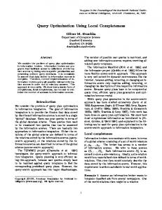
carry-chain. A slice mapping of a novel (6, 0, 6; 5) GPC is shown in Fig. 5(a). In the least significant LUT (the rightmost one), two full-adders are used to compute the sum out of five inputs. An additional input of the same column is added by the full-adder of the carry chain. The shown XOR gates are necessary to complete the carry logic to a ripple carry adder (RCA). A similar structure is used in the second LUT, but now the two carry bits are computed and fed to the RCA. This structure is repeated, leading to the (6, 0, 6; 5) GPC. Its efficiency is E = 1.75 which is the highest efficiency reported so far. Even the ternary adder or the 4 : 2 compressor have a lower efficiency of E = 1.5 for the same size (k = 4). Its critical path only consists of a single LUT delay plus four stages of fast carry propagation. A GPC with different input configuration is shown in Fig. 5(b), namely the (1, 3, 2, 5; 5) GPC. Although it has a lower efficiency of E = 1.5, it may be favorable in cases where not all of the inputs of the (6, 0, 6; 5) GPC are utilized. The delay is identical to that of the (6, 0, 6; 5) GPC. Note that the carry-in of the (6, 0, 6; 5) GPC can not be used as additional input due to routing constraints within the slice (when the 0-input of the carry-chain MUX is fed from a slice input). VI. R ESULTS The proposed ILP formulation was integrated within the open-source arithmetic core generator FloPoCo1 [17], which 1 Currently
managed in a branch of the FloPoCo subversion repository
Fig. 6: Resulting number of LUTs over the number of input bits using the heuristic [11] and the proposed ILP model for (a) Virtex 4 and (b) Virtex 6 FPGAs
is a nice framework that supports the handling of compressor trees as a bit heap (including signed number support) [11] as well as the support for VHDL code generation and automated tests. It also includes the recently proposed heuristic compression method [11] which makes it perfectly suitable for comparisons as both methods work on identical data structures and use the same VHDL generation framework. To be able to provide our method as open-source tool it was decided to use the open-source ILP solver SCIP [16], although it is well known that the commercial CPLEX ILP optimizer is much faster (we observed speedups about 10× which is confirmed by a benchmark provided at [16]). A. Evaluation of the Optimization Quality To evaluate the performance of the compression we implemented a multiple-input adder with a variable number of inputs as well as a variable word size. We chose this type of circuit because it uses only the compressor tree plus an additional VMA at the output. As VMA we chose a common two-input adder for performance reasons. In the experiments we target Virtex 4 and Virtex 6 FPGAs from Xilinx as candidates with different LUT input sizes. For Virtex 4 (4input LUTs), we used the same LUT-based GPCs that are used in the FloPoCo framework, namely the (3; 2), (4; 3) and (1, 3; 3) GPCs with LUT cost 2, 3 and 3, respectively. FloPoCo allows the specification of a target frequency to decide how many pipeline stages are used. This frequency was set to
TABLE III: Synthesis results for Virtex 4 FPGA Heuristic [11] Size LUT4 FF [bits]
Slices
fmax LUT4 [MHz]
FF
Slices
fmax [MHz]
16 25 36 49 64 81 100 121 144 169 196 225 256
25 29 59 73 109 117 174 181 255 277 368 410 459
501.5 455.2 489.5 444.8 412.9 420.7 414.8 332.6 376.2 344.8 355.0 333.9 343.3
28 46 54 79 123 141 181 242 272 309 407 444 506
21 45 56 78 120 135 178 247 273 317 416 451 518
25 39 35 46 100 106 109 211 223 197 340 349 438
562.4 562.1 491.4 481.9 471.5 477.8 454.6 435.4 441.1 428.3 423.2 424.3 410.3
401.9 –
217.8 219.6 30.3% -19.6%
34 45 78 123 181 209 267 332 395 492 582 622 706
Avg.: 312.8 Imp.: –
(a)
(b)
Fig. 7: Compression of a 16-bit 16-input adder: (a) FloPoCo Heuristic, (b) Proposed ILP solution
600 MHz for the heuristic to yield similar timing results and thus comparable resource consumptions. The input word size as well as the word length were varied from 4 to 16 leading to rectangular bit heaps of size 16 to 256 bit. As the ILP optimization may be very time-consuming, SCIP was set to a time limit of 1 hour, which we thought is reasonable. In most cases, a valid solution was found within seconds or minutes which already outperformed the heuristic results. The current implementation allows to interrupt the optimization at any point and VHDL code is generated for the best solution found so far (if any). The resulting LUT cost from the optimization using the heuristic [11] and the proposed ILP method (with respecting flip-flops cost for pipelining) are shown in Fig. 6(a). It can be observed that the LUT costs follow a fairly linear trend related to the number of bits, independent of the method used. However, the proposed method has a much lower gradient of 1.9 LUT/bit compared to 2.5 LUT/bit. The average LUT reduction is 22.8%. Up to a complexity of 100 bits, an optimal solution was always found within the given time limit, often within a few seconds. As the trend in Fig. 6 continues for higher complexities, it can be assumed that the non-optimal solutions are not too far from being optimal.
proposed ILP
20 39 63 86 108 132 173 182 243 283 328 345 386
183.7 195.1 – –
170.6 466.5 12.5% 16.1%
The same procedure was applied to Virtex 6 FPGAs which allow the use of 6-inputs LUTs. Here, much more LUT-based GPCs are possible and some of them use the fact that 6-input LUTs can be configured to two 5-input LUTs with shared inputs (which is the case for GPCs with five or less inputs). The LUT-based GPCs used from the FloPoCo framework have the configurations (6; 3), (1, 5; 3), (5; 3), (1, 4; 3), (4; 3), (2, 3; 3), (1, 3; 3). In addition to that, we used the fastest of the Virtex 6 optimized GPCs from [13] (1, 4, 1, 5; 5), (1, 4, 0, 6; 5) and (2, 0, 4, 5; 5) as well as the (1, 3, 2, 5; 5) and (6, 0, 6; 5) GPCs proposed above for the ILP optimization. The results are shown in Fig. 6(b) which shows a similar progression. The obtained gradient is 0.65 LUT/bit compared to the 0.9 LUT/bit of the heuristic. The average LUT reduction is 30.4%. The number of compressor stages could be drastically reduced compared to the heuristic, even though the optimization goal was the cost minimization (the stage minimization of Section IV-C was not used). The average reduction of stages is 45.1% (from 7.8 stages to 4.3) and 28.3% (from 3.5 stages to 2.5) for Virtex 4 and Virtex 6, respectively. The compression of the largest 256 bit instance is shown in Fig. 7. While the heuristic tries to reduce the maximum height in each step (Fig. 7(a)) there are some pretty high columns in the ILP solution (Fig. 7(b)). It is interesting to note that this is contrary to the well known compression using full-adders. There, the strategy for minimal depth is to always first reduce the largest column [2]. Hence, one can conclude that the reduction of the highest column may not always be the best strategy when using GPCs. B. Synthesis Experiments All designs from the previous subsection were also synthesized for Virtex 4 (XC4VLX100-10FF1148) and Virtex 6 (XC6VLX760-FF1760) FPGAs using Xilinx ISE v13.4. The standard ISE settings often result in designs with poor slice utilization, i. e., full slices are often used to implement single
TABLE IV: Synthesis results for Virtex 6 FPGA Heuristic [11] Size LUT6 FF [bits] 16 25 36 49 64 81 100 121 144 169 196 225 256
12 24 32 44 59 76 96 116 134 161 189 216 251
Avg.: 108.5 Imp.: –
Slices
proposed ILP fmax LUT6 [MHz]
FF 9 25 36 40 48 59 98 112 121 155 160 236 251
Slices 3 7 7 10 13 15 20 25 24 30 35 57 55
fmax [MHz]
7 11 13 15 19 21 47 26 28 60 76 81 74
3 6 9 12 16 20 26 32 35 43 50 56 66
478.0 636.5 595.6 492.4 407.7 442.9 435.9 401.6 383.9 396.8 358.0 327.2 338.3
10 26 27 35 47 56 77 89 94 119 131 192 204
639.4 452.9 603.1 407.7 506.8 480.1 437.5 438.6 469.0 470.6 408.0 364.0 372.3
36.8 –
28.8 –
438.1 –
85.2 103.8 23.2 465.4 21.5% -182.4% 19.5% 6.2%
LUTs. Hence, the slice utilization was obtained by setting the map tool to a minimum packfactor (option -c 1) yielding a maximum packing density. This leads to more realistic results as the situation is similar to a device utilization close to 100%. Even if the routing may not possible in such situations, a valid routing was found in all the considered cases. To get a realistic timing evaluation, the maximum frequency was obtained by inserting registers at the inputs. The synthesis results for the LUT, FF and slice usage as well as the maximum clock frequency are listed in Table III and Table IV. Even though the number of flip-flops is significantly higher in the proposed method, the slices could be reduced by 12.5% and 19.5% on average for Virtex 4 and Virtex 6, respectively, while achieving a higher performance. This results from the fact that most of the flip-flops are located in the same slice as the compressors do and, thereby, not require extra resources. VII. C ONCLUSION A novel method for optimizing compressor trees on FPGAs based on ILP is proposed. In contrast to previous ILP formulations [4], [6], [8] it focusses on minimizing the resources for high throughput pipelined designs rather than minimizing the combinatorial delay. It was shown that average LUT reductions of 22.8% for 4-input FPGAs and 30.4% for modern 6-input LUT FPGAs (using novel GPCs in addition) compared to a recent heuristic [11] can be achieved. This leads to average slice reductions of 19.5% for Virtex 6 FPGAs. The ILP formulation is flexible and can be simply adjusted for a minimal stage count and compressors with variable columns. Further work has to be done for comparison with previous
work [4], [6], [8] and to reduce the complexity in case an optimal solution can not be found in a reasonable time. Instead of optimizing the whole compressor tree it could be simply applied stage-by-stage. Alternatively, a complexity reduction could be achieved by a preprocessing stage, where large high-efficient compressors (like the 4 : 2 compressor or the (6, 0, 6; 5) GPC) are applied to the bits they perfectly cover. This should drastically reduce the problem size and should still be close to the optimum. R EFERENCES [1] C. Wallace, “A Suggestion for a Fast Multiplier,” IEEE Transactions on Electronic Computers, no. 1, pp. 14–17, 1964. [2] L. Dadda, “Some Schemes For Parallel Multipliers,” Alta Frequenza, vol. 45, no. 5, pp. 349–356, 1965. [3] H. Parandeh-Afshar, P. Brisk, and P. Ienne, “Efficient Synthesis of Compressor Trees on FPGAs,” in Asia and South Pacific Design Automation Conference (ASPDAC). IEEE, 2008, pp. 138–143. [4] ——, “Improving Synthesis of Compressor Trees on FPGAs via Integer Linear Programming,” in Design, Automation and Test in Europe (DATE). IEEE, 2008, pp. 1256–1261. [5] H. Parandeh-Afshar, A. Neogy, P. Brisk, and P. Ienne, “Compressor Tree Synthesis on Commercial High-Performance FPGAs,” ACM Transactions on Reconfigurable Technology and Systems (TRETS), vol. 4, no. 4, pp. 1–19, 2011. [6] T. Matsunaga, S. Kimura, and Y. Matsunaga, “Power and Delay Aware Synthesis of Multi-Operand Adders Targeting LUT-Based FPGAs,” International Symposium on Low Power Electronics and Design (ISLPED), pp. 217–222, 2011. [7] ——, “Multi-Operand Adder Synthesis Targeting FPGAs,” IEICE Transactions on Fundamentals of Electronics, Communications and Computer Sciences, vol. E94-A, no. 12, pp. 2579–2586, Dec. 2011. [8] ——, “An Exact Approach for GPC-Based Compressor Tree Synthesis,” IEICE Transactions on Fundamentals of Electronics, Communications and Computer Sciences, vol. E96-A, no. 12, pp. 2553–2560, Dec. 2013. [9] W. J. Stenzel, W. J. Kubitz, and G. H. Garcia, “A Compact HighSpeed Parallel Multiplication Scheme,” IEEE Transactions of Computers, no. 10, pp. 948–957, 1977. [10] M. D. Ercegovac and T. Lang, Digital Arithmetic. Elsevier, 2004. [11] N. Brunie, F. de Dinechin, M. Istoan, G. Sergent, K. Illyes, and B. Popa, “Arithmetic Core Generation Using Bit Heaps,” in IEEE International Conference on Field Programmable Logic and Application (FPL), 2013, pp. 1–8. [12] M. Kumm, M. Hardieck, J. Willkomm, P. Zipf, and U. Meyer-Baese, “Multiple Constant Multiplication with Ternary Adders,” in IEEE International Conference on Field Programmable Logic and Application (FPL), 2013, pp. 1–8. [13] M. Kumm and P. Zipf, “Efficient High Speed Compression Trees on Xilinx FPGAs,” in Methoden und Beschreibungssprachen zur Modellierung und Verifikation von Schaltungen und Systemen (MBMV), 2014. [14] ——, “High Speed Low Complexity FPGA-Based FIR Filters Using Pipelined Adder Graphs,” in IEEE International Conference on FieldProgrammable Technology (FPT), 2011, pp. 1–4. [15] IBM. (2014, Feb.) High-Performance Mathematical Programming Solver for Linear Programming, Mixed Integer Programming, and Quadratic Programming. [Online]. Available: http://www.ibm.com/software/commerce/optimization/cplex-optimizer/ [16] Konrad-Zuse-Zentrum f¨ur Informationstechnik Berlin. (2014) A MIP Solver and Constraint Integer Programming Framework. [Online]. Available: http://scip.zib.de [17] (2013) FloPoCo Project Website. [Online]. Available: http://flopoco.gforge.inria.fr