JOURNAL OF APPLIED PHYSICS 98, 093907 共2005兲
Polarization-modulated magnetic soft-x-ray transmission microscopy Bo-Sun Kang,a兲 Dong-Hyun Kim, Erik Anderson, and Peter Fischerb兲 Ernest Orlando Lawrence Berkeley National Laboratory, Center for X-ray Optics, 1 Cyclotron Road, Berkeley, California 94720
Gyuseong Cho Korea Advanced Institute of Science and Technology, 373-1 Guseong-dong, Yuseong-gu, Daejeon 305-701, Republic of Korea
共Received 10 May 2005; accepted 27 September 2005; published online 14 November 2005兲 An adjustable aperture element has been integrated into the full-field soft-x-ray microscope at the Advanced Light Source to select either the right or left elliptically polarized x rays emitted at an inclined angle from a bending magnet. Magnetic contrast recorded at the Fe L3 edge in a 59-nm-thin Gd25Fe75 layer can be modulated and scales with the degree of circular polarization in agreement with theoretical calculations. Nonmagnetic background contributions can be reduced and magnetic contrast is enhanced by comparing two images taken with opposite circular polarization. The fast modulation speed of this technique allows for lock-in recording schemes in high-resolution magnetic soft-x-ray microscopy. © 2005 American Institute of Physics. 关DOI: 10.1063/1.2128051兴 I. INTRODUCTION
Nowadays, magnetism of low-dimensional systems, such as thin films, multilayered systems, and geometrically confined elements, is the focus of both fundamental and applied studies. A thorough characterization of magnetic microstructures in such systems, occurring on short length scales in the nanometer range, provides valuable key information. Magnetic exchange lengths, which characterize the region of spin inhomogeneities and thus act as characteristic length scale, are determined from material specific constants of the species to be studied, such as the anisotropy and the exchange constant. To illustrate the associated length scales, the magnetic exchange length with respect to the stray field in a weak ferromagnetic system, e.g., permalloy 共Ni80Fe20兲, has a value of 5.7 nm while for a hard magnetic system such as SmCo5 the corresponding exchange length with respect to the anisotropy drops to 1.3 nm. The behavior of the magnetic domain structure in external magnetic fields is of particular interest when the geometrical size of the objects approaches these characteristic length scales. The study of the nucleation and its stochastical character, the reproducibility of magnetic domain configurations on short length scales within full magnetization reversal cycles, and their relation to local anisotropies, defects, and inhomogeneities are of utmost interest. In addition to the quasistatic characteristics of magnetic microstructures, their dynamics on a microsecond to picosecond time scale have recently attracted significant scientific interest driven again by scientific curiosity and feasible technological applications. While the areal density and the miniaturization in magnetic storage and sensor applications have witnessed a dramatic increase during the last decade of a factor of more than 1000, the associated dynamical behavior a兲
Also at KAIST, 373-1 Guseong-dong, Yuseong-gu, Daejeon 305-701, Republic of Korea. b兲 Electronic mail:
[email protected] 0021-8979/2005/98共9兲/093907/4/$22.50
of the magnetization, e.g., the writing speed of magnetic information, has not been increased to a similar extent, since reversing the magnetization by applying an opposite magnetic field relies on a rather slow process launched by thermal fluctuations of the magnetization. Current concepts of a fast magnetization reversal consider the precessional motion of electronic spins with time scales in the subnanoscale regime. To experimentally study these magnetic domain configurations and their spatial and temporal behaviors several versatile powerful techniques have been developed so far. Amongst others Kerr microscopy is a full-field magnetic imaging system with magnetic contrast provided by the magneto-optical Kerr effect 共MOKE兲.1 MOKE is manifested by the change of the polarization and/or the intensity of incident polarized light when it is reflected from the magnetic sample surface.2 Kerr microscopy is a well-established technique with a diffraction-limited spatial resolution and a high time resolution limited by the time structure of the engaged laser systems. Since the detectable MOKE signal is weak, it is common in Kerr microscopy to use polarizationmodulated light to enhance and to separate the magnetic contrast from the nonmagnetic background signal. Being an optical technique, Kerr microscopy cannot be applied to explore magnetic domain behavior on a submicrometer length scale. The x-ray counterpart to MOKE is x-ray magnetic circular dichroism 共X-MCD兲, which detects the dependence of the absorption of circularly polarized x rays on the magnetization of the ferromagnetic species. In effect, X-MCD reflects the difference in the x-ray absorption coefficient for parallel and antiparallel orientations between the magnetization in the sample and the helicity of the x rays. The magnetic contributions to the x-ray absorption coefficient occur predominantly in the vicinity of element-specific x-ray absorption edges, which correspond to binding energies of inner-core atomic levels. At the L edges of 3d transition metals, such as Fe, Co, and Ni, with binding energies between
98, 093907-1
© 2005 American Institute of Physics
Downloaded 06 Dec 2005 to 143.248.62.221. Redistribution subject to AIP license or copyright, see http://jap.aip.org/jap/copyright.jsp
093907-2
J. Appl. Phys. 98, 093907 共2005兲
Kang et al.
700–800 eV X-MCD reaches values up to almost 30%. Therefore X-MCD can be considered as magnetic contrast mechanism if it is combined with imaging techniques relying on the photoabsorption process. The first study reported in literature engaged a photoemission electron microscope. Magnetic soft-x-ray transmission microscopy combines X-MCD with high-resolution x-ray microscopy.3,4 Since the refractive index of x rays is close to 1, conventional lenses do not work for x rays. However, it is well established that Fresnel zone plates used as optical elements allow for imaging x rays with a very high lateral resolution which is largely determined by the width of the outermost ring in the circular grating structures with a radially increasing line density. Currently the best resolution that has been demonstrated is as low as 15 nm.5 At synchrotron-radiation laboratories circularly polarized x rays with photon energies in the sub-keV to keV regime are readily available nowadays. They are easy to obtain at a bending magnet where the radiation emitted above and below the orbital plane of the synchrotron yields elliptical polarization of reversed helicity. Helical undulators produce high brilliant polarized x rays where the degree of polarization can be modulated by mechanically shifting the phase of the permanent magnet array allowing for a switching rate in the 0.1 Hz regime. In the hard x-ray regime quarter-wave plates utilize dynamic scattering theory to generate polarized light if the photon propagation direction is modulated in the vicinity of the Bragg angle by a few arcsec. This can be achieved at a high switching rate.6 Here we report on a recent development at a full-field imaging x-ray microscopy station, located at a bending magnet that allows us to modulate the x-ray polarization by an adjustable slit aperture system. Thus magnetic images can be recorded where the nonmagnetic background is strongly reduced and the magnetic contrast is considerably increased. II. EXPERIMENTAL DETAILS
For our studies we used the full-field soft-x-ray transmission microscope XM-1 共BL 6.1.2兲 at the Advanced Light Source 共ALS兲 in Berkeley, CA. XM-1 is located at a bending magnet station. The setup of the x-ray microscope and its application to image magnetic systems are described elsewhere.7 X rays being reflected from a SiRu-coated mirror at an angle of 3° are transmitted through a condenser zone plate 共CZP兲 which together with a 20m diameter pinhole acts as a linear monochromator due to the wavelength dependence of the focal length of the CZP. The CZP has a diameter of 9 mm with an outermost zone width of 60 nm and a total of more than 50 000 zones. After passing through the sample a magnified image of the transmitted photons is created by a second microzone plate 共MZP兲 with 400 zones, an outermost zone width of 40 nm, and a diameter of 65m. The image is then recorded with a commercial backside-illuminated thinned charge-coupled device 共CCD兲 camera. In order to modulate the x-ray helicity and thus the magnetic contrast we installed a vertically movable slit aperture upstream to the condenser zone plate in order to select either the radiation emitted above or below the orbital plane. The
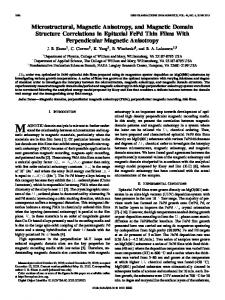
FIG. 1. 共Color online兲 Schematical arrangement of the vertically movable aperture systems with a variable slit width indicating the masking of the condenser zone plate. A and B are the areas for slit widths of 5 and 2 mm, respectively. The center positions of the slits are indicated by hA and hB.
accuracy for the vertical positioning was 0.2 mm. The slit width could be adjusted with an accuracy of about 0.1 mm and varied from 0 to 10 mm. The schematic beam cross section on the condenser with different sizes of slit openings is shown in Fig. 1. The magnetic images were taken at the Fe L3 edge at 706 eV. The sample was a 59-nm-thin amorphous Gd25Fe75 single layer used in previous experiments at XM-1. Due to the polyimide substrate relatively large magnetic patterns are observed largely determined by local pinning centers. Typical illumination times are in the 1–3 s range following the continuous decrease of the beam current in the storage ring. By varying the slit width and height position of our aperture system we were able to scan vertically along the beam profile so as to obtain magnetic images with different degrees of circular polarization. The magnetic contrast was determined from the images by analyzing the measured intensity recorded in the pixels of the CCD. To compare intensities the images were normalized to the beam current at the time of recording. We used the following expression for the magnetic contrast C: C=
I+ − I− , I+ + I−
with I+ and I− being the intensities at dark and bright regions. To average over the statistical fluctuations and the nonuniform illumination intensity scans across the domain boundary of adjacent magnetic domains at 30 different regions were carried out and analyzed yielding an average value of the magnetic contrast for the entire field of view of an image. The degree of circular polarization PC as a function of the vertical angle from the electron orbital plane was calculated by PC =
兩IR − IL兩 , IR + IL
where IR and IL are the x-ray intensities with their polarization states being right and left, respectively. The vertical distance at the location of the CZP was determined taking into account a distance between source and condensor of 15 m.
Downloaded 06 Dec 2005 to 143.248.62.221. Redistribution subject to AIP license or copyright, see http://jap.aip.org/jap/copyright.jsp
093907-3
Kang et al.
J. Appl. Phys. 98, 093907 共2005兲
FIG. 3. 共Color online兲 Profile of the magnetic contrast 共for a definition see text兲 vs vertical position of the aperture system 共left scale兲 in comparison with theoretical calculations of the circular degree of polarization taking into account the averaging due to the opening of the slit 共right scale兲.
FIG. 2. Magnetic soft-x-ray transmission microscopy images of a 59-nmthin amorphous layer of Gd25Fe75 recorded at a photon energy of 706 eV 共Fe L3 edge兲. 共a兲 Recorded with a 5 mm aperture located 2.5 mm above the orbital plane, 共b兲 aperture located 2.5 mm below the orbital plane, and 共c兲 image obtained by dividing 共a兲 by 共b兲 shows reduced nonmagnetic background and increased magnetic contrast. 共d兲 Image recorded with the aperture located at the center of the orbital plane.
PC was calculated at various vertical positions and averaged by the slit width. III. RESULTS
Figures 2共a兲 and 2共c兲 show two images taken with slit positions of +2.5 and −2.5 mm above/below the electron orbital plane. The slit width was 5 mm, i.e., half of the condenser was blocked by the aperture. The reversal of the magnetic contrast is clearly observed with respect to the slit position, which indicates the reversal of the degree of polarization. By analyzing the profile of the averaged magnetic contrast, we could determine the vertical position of the beam center, i.e., where the magnetic contrast disappears 共Fig. 3兲. This position was found to be consistent with an independent measurement of the vertical intensity profile of the beam with a photodiode detector. Figure 2共d兲 shows the corresponding magnetic image recorded at the center of the electron orbit where no magnetic contrast is observed since there is no circular degree of polarization. By analyzing images recorded with opposite helicity one can reduce nonmagnetic background contributions and also enhance significantly the magnetic contrast compared to the individual images. This is demonstrated in the image shown in Fig. 2共c兲 which was obtained by dividing Fig. 2共a兲 by Fig. 2共b兲. The profile of the magnetic contrast derived from the magnetic x-ray images as a function of the vertical position of the aperture is plotted in Fig. 3 共left scale兲. The right scale corresponds to the profile of degree of circular polarization calculated from theory taking into account the averaging of
the polarization due to the limited slit width of the aperture. The good agreement between the experimental and theoretical profiles proofs that a degree of polarization up to 70% can be achieved with this technique at a bending magnet station. Furthermore the slit widths between 2 and 5 mm seem to have no significant influence and therefore masking the top/bottom half of the condenser is a good compromise. A further reduction of the slit width is not acceptable with regard to a dramatic loss of intensity.
IV. CONCLUSIONS AND OUTLOOK
We have demonstrated that using a vertically adjustable aperture system located upstream to the condenser in a fullfield x-ray microscope one can selectively illuminate the specimen with x rays of opposite circular polarization. The partial illumination of the condenser does not degrade the image quality. The magnetic contrast can be enhanced and nonmagnetic background contributions significantly suppressed thereby increasing the magnetic sensitivity in systems with an only weak magnetic X-MCD contrast. The vertical profile of the magnetic contrast allows for an exact determination of the orbital plane position. This opens the possibility to use this setup for accurate beam line alignment issues. The reduction of intensity with increasing vertical distance was found to be compensated by the increase of magnetic contrast. In future this technique opens the possibility to modulate the degree of polarization at high frequencies by opening/ closing the top/bottom aperture in a double slit system. In principle the magnetic signal can be modulated with a lock-in amplifier so that even small signals can be separated from the background. Compared to current developments of full-field x-ray microscopes at high brilliant helical undulator sources where more complex optical concepts have to be engaged in order to match the numerical aperture8 the operation of a full-field x-ray transmission microscope at a high-flux bending mag-
Downloaded 06 Dec 2005 to 143.248.62.221. Redistribution subject to AIP license or copyright, see http://jap.aip.org/jap/copyright.jsp
093907-4
J. Appl. Phys. 98, 093907 共2005兲
Kang et al.
netic source seems to be a cost-effective alternative, in particular, for applications to nanomagnetism where the control of the polarization of the x rays is essential.
program for financial support. This work was supported by the Director, Office of Science, Office of Basic Energy Sciences, of the U.S. Department of Energy under Contract No. DE-AC03-76SF00098.
ACKNOWLEDGMENTS 1
We would like to thank S. Rekawa, D. Kemp, K. Bradley, R. Oort 共Center for X-ray Optics兲, and the Survey and Alignment Group at the ALS 共A. Gavidia, D. Ellis, H. Meyer, and D. Jones兲 for their support to align the beam line for this experiment and D. T. Attwood for his continuous support of XM-1. One of the authors 共B.S.K.兲 would like to thank the Korean Institute of Science and Technology Evaluation and Planning 共KISTEP兲 and Korean Ministry of Science and Technology 共MOST兲 of Korean government through national nuclear fellowship of Korean nuclear R&D
S.-B. Choe, D.-H. Kim, Y.-Ch. Cho, H.-J. Jang, K.-S. Ryu, H.-S. Lee, and S.-Ch. Shin, Rev. Sci. Instrum. 73, 2910 共2002兲. C.-Y. You and S.-Ch. Shin, Appl. Phys. Lett. 69, 1315 共1996兲. 3 P. Fischer, G. Schütz, G. Schmahl, P. Guttmann, and D. Raasch, Z. Phys. B: Condens. Matter 101, 313 共1996兲. 4 P. Fischer, G. Denbeaux, T. Eimüller, D. Goll, and G. Schütz, IEEE Trans. Magn. 38, 2427 共2002兲. 5 W. Chao, B. D. Harteneck, J. A. Liddle, E. H. Anderson, and D. T. Attwood, Nature 共London兲 435, 1210 共2005兲. 6 C. Giles et al., Rev. Sci. Instrum. 66, 1549 共1995兲. 7 P. Fischer et al., Rev. Sci. Instrum. 72, 2322 共2001兲. 8 P. Guttmann, B. Niemann, S. Rehbein, C. Knöchel, D. Rudolph, and G. Schmahl, J. Phys. IV 104, 85 共2003兲. 2
Downloaded 06 Dec 2005 to 143.248.62.221. Redistribution subject to AIP license or copyright, see http://jap.aip.org/jap/copyright.jsp