MEASUREMENT SCIENCE REVIEW, Volume 1, Number 1, 2001
Portable System for High Resolution ECG Mapping Rosík V., Tyšler M., Jurko Š., Rášo R., Turzová M. Institute of Measurement Science, Slovak Academy of Sciences, Bratislava, Slovak Republic email:
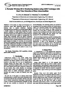
[email protected] Abstract In the paper a high resolution ECG mapping system based on personal computer or notebook equipped with fast IEEE 1284 parallel port working in ECP mode is introduced. Concept of the device enables high-resolution multi-channel ECG mapping using up to 256 ECG leads. Concept of the device and description of electrical and mechanical solution of portable 134-channel system is given. 1. Introduction Body surface potential mapping (BSPM) is a non-invasive electrocardiographic method enabling more precise diagnostics of cardiac diseases. However, results obtained from maps constructed from 24 to 32 leads showed that the information contents is not substantially greater than that of standard 12-lead ECG. It is hoped that maps constructed from more leads measured with better accuracy could improve the diagnostic information in BSPM. ProCardio 7 system described in this paper is designed for recording of ECG signals from limb leads and up to 134 chest leads. It enables high resolution BSPM using several electrode sets. 2. Method and Results Concept of the mapping system ProCardio 7 mapping system is designed as a specialized portable or mobile configuration of a multichannel measuring subsystem placed in patient terminal box PT134 connected to a personal computer through fast parallel port IEEE 1284 working in ECP mode. The patient terminal is powered by an isolated power supply placed in separate shielded box. Block scheme of the system is shown in Fig.1.
Patient terminal
C1÷C16
C17÷C32
Module for limb leads
DAS Controller,
Module for chest leads 1 Module for chest leads 2
optical insulation
R L F N
MUX 256 PGA ADC 12
WCT C112÷C128
Module for chest leads 8
FIFO buffer memory and
IEEE 1284 (ECP mode) Parallel port Controller
Personal computer IEEE 1284 Parallel port
Isolated power supply Fig.1. Block scheme of the mapping system with patient terminal PT134.
27
Measurement in Biomedicine ● V. Rosík et al.
This concept enables independent design and selection of basic parts of the mapping system and setting of an optimal configuration corresponding to the user's requirements to number of channels, portability of the system, signal processing speed, and the system price. Structure of the patient terminal unit enables to build a measuring system respecting regulations for medical electrical equipment of type BF or CF using commercial personal computer or notebook. From the user's point of view, measuring system has following important features: - standard PC or notebook with the fast parallel port is used; no hardware intervention into the PC unit is needed during system installation or service, - optical isolation of the measured object enables measurement of signals for body surface potential mapping and also acquisition of patient's heart electrograms (with CF-type unit), - contact of measuring electrodes and integrity of measured leads is continuously checked and faulty leads are reported on computer screen during the test phase of the measurement process, - upper cut-off frequency of measuring channels can be set under program control depending on the measured signals and the actual sampling frequency, - individually programmable gain of each measuring channel enables optimal resolution of signals even with very different amplitudes, - all standard bipolar and unipolar ECG signals are generated by the hardware of the measuring channels and no additional computations of combined signals are required during recording. Patient terminal unit Patient terminal PT134 represents a specialized data acquisition system (DAS) for use in biology and biomedicine. It consists of three basic sections: - amplifying section, - measuring section containing DAS and optoelectronic insulation, - interface section with microcontroller and fast parallel port driver. Internal structure of the amplifying section is shown in Fig. 2. Its task is to amplify ECG signals measured on the body surface or on epi- and endocardium and optimize their amplitudes for connection to the DAS inputs. The amplifying unit fulfills safety requirements for ECG measuring equipment [1]. Arrangement of the measured leads conforms to demands for ECG lead standards [2, chap.3.2.2.]. Disposable adhesive pre-gelled Ag-AgCl electrodes for ECG recording are used because of their low differences of the polarizing potential. Signals from limb electrodes R, L, F are processed in one limb lead module LL6A, signals from chest electrodes C1, C2, … are processed in up to eight 16-channel unipolar chest lead modules CL16A. Full configuration of the PT134 patient terminal contains 6 measuring channels for standard limb leads and 128 measuring channels for unipolar chest leads. Neutral electrode N on the patient's left leg is connected to the output of a neutralization amplifier placed in the limb lead module. It supplies to the measured object (patient) an amplified and inverted signal of the common mode voltage derived from the R electrode. By this active neutralization level of disturbing common mode voltage on the measured patient caused by the presence of mains in the examination rooms is reduced. Common mode interference caused by currents induced into lead cables by capacitive coupling with mains is minimized by shielding of the lead cables. To reduce the influence of high parasitic capacity of cable shielding on the stability of the active neutralization loop, shielding of all cables is also driven by the common mode voltage signal derived from the R electrode. Signals from R, L and F electrodes are preamplified in the limb lead module and connected to the standard Wilson/Golberger resistor network. Signals from its nodes are processed in 6 differential amplifiers and signals of Einthoven's bipolar limb leads I, II, III and Golberger's augemented limb leads aVR, aVL, aVF are available on their outputs. Wilson's central terminal potential (WCT) obtained in the Wilson/Golberger resistor network is used as the reference potential for all unipolar leads and is fed to the inverting inputs of all differential amplifiers in the chest lead modules CL16A.
28
MEASUREMENT SCIENCE REVIEW, Volume 1, Number 1, 2001
Module LL6A
R L
>
F
>
Active Lead Cable Shielding A=0,98
Limb Lead Preamplifiers (6 channels) A=34
+15V -15V
RM >
RM > >
3 //
Wilson / Goldberger Resistor Network
// >
6
6
// W
>
Differential amplifiers and active filters (fh) A=29,41
+15V -15V AGND DGND
6 // FRI0 FRI1 M/TI
Active patient
Module CL16A No.1
< C1 C2 C3 C4
C13 C14 C15 C16
EBNKI0 ALI0 ALI1 ALI2 ALI3 MXO
16 channel analog multiplexer
+15V -15V AGND DGND
+15V -15V
Active Lead Cable Shielding A=0,98