76
IEEE TRANSACTIONS ON POWER ELECTRONICS, VOL. 17, NO. 1, JANUARY 2002
Design and Precise Realization of Optimized Current Waveforms for an 8/6 Switched Reluctance Drive Patrick L. Chapman, Member, IEEE, and Scott D. Sudhoff, Member, IEEE
Abstract—Optimized shaping of the stator current in the switched reluctance motor drive can be used to mitigate electromagnetic torque ripple and decrease the rms current. Previously, optimal current waveshaping has been based upon defining the optimal current waveform as a set of discrete points and interpolating intermediate points. In this work, an alternate approach is employed in which the current waveform is treated as a set of harmonic coefficients, rather than as an array of discrete values. This has advantages in terms of computation speed and in programming of the microcontroller. A second feature of this new method is that it incorporates a multiple reference frame estimator/regulator that ensures each harmonic of the current converges to its commanded value thereby avoiding the degradation in performance associated with imperfect tracking that other methods are susceptible to. The experimental and simulated results demonstrate the optimality of the waveforms and the importance of the multiple reference frame estimator/regulator, particularly in mitigating torque ripple. Index Terms—Electric drive, optimal control, switched reluctance, torque ripple.
I. INTRODUCTION
T
HE switched reluctance machine (SRM) has several attractive features, including low-cost and rugged construction. However, this drive also exhibits some difficulties in performance, particularly with regard to efficiency and torque ripple. One method to improve performance at low to medium speeds is optimal shaping of the stator current waveform. This method is attractive since it requires little, if any, additional hardware when compared to a standard current-regulated SRM drive. Optimized shaping of the stator currents has been considered in several previous works [1]–[6]. In these, several attempts were made to minimize or eliminate torque ripple with varying degrees of assumption and applicability. For example, some authors used prohibitively simplified representations of the machine, used analysis pertinent to only specific machine designs, or neglected the effect of constrained voltage. For example, the experimentally validated method set forth in [1] was shown to yield good results, but since saturation of the machine was neglected, the applicability of the analysis is not as general as desired. Among the most recent efforts was [2] wherein the current
Manuscript received August 16, 2000; revised October 22, 2001. Recommended by G. K. Dubey. This work was supported by the Office of Naval Research (ONR) under Contracts N00014-98-1-0727 and N00014-98-1-0716. P. L. Chapman is with the University of Illinois at Urbana-Champaign, Urbana, IL 61801 USA (e-mail:
[email protected]). S. D. Sudhoff is with Purdue University, West Lafayette, IN 47907 USA. Publisher Item Identifier S 0885-8993(02)02173-7.
waveforms were designed to eliminate torque ripple for a drive with general characteristics and constrained bus voltage. Another method, set forth in [3], seeks to eliminate torque ripple and minimize rms current subject to constrained bus voltage. This seems to be the first instance of recognizing the secondary objective of minimizing rms current while minimizing torque ripple. These methods are similar in a methodology which consists of representing the optimal current waveforms into arrays of discrete points. The measured nonlinear flux linkage versus current and rotor position data is used along with coenergy techniques to determine the torque versus current and rotor position relationship. Numerical optimization is applied to determine each of the discrete points in the resulting current waveform array. Numerical differentiation is used in enforcing the voltage constraint. The method presented herein mainly differs in that it treats the current waveform as a small set of harmonic coefficients rather than as a long array of discrete points of current values versus rotor position. This has the advantages of computational efficiency, analytical rather than numerical differentiation to enforce the voltage constraint, reduced memory requirements in the controller, elimination of the need for interpolation between discrete positions, and the property of being readily amenable to the use of a multiple reference frame synchronous estimator/regulator which can be used to ensure that the desired current waveform is actually achieved. The method is also different from previous work is that it has the flexibility to directly use torque versus current and position characteristic of the machine, in addition to these obtained by using coenergy principles. Another characteristic of previous work has been that the assumption that standard current regulation techniques (such as hysteresis and delta modulation [7]) ensure the current will satisfactorily track the command. However, it has been shown in [8], [9] that satisfactory tracking may not be achieved as hysteresis and delta modulator generally do produce error. It happens that the average torque is most sensitive to the fundamental component of the current, and that the torque ripple is generally most sensitive to the harmonics in the current. Therefore, it is important that every harmonic of the current be realized as precisely as possible to ensure that the optimized set point is achieved. The problem becomes more evident at lower switching frequencies. This work makes use of a multiple reference frame synchronous estimator/regulator that ensures the nonsinusoidal current command is precisely obtained in the steady state. While originally set forth for permanent-magnet motor drives [8], it is applied here to the 8/6 SRM drive. A key point of the
0885–8993/02$17.00 © 2002 IEEE
CHAPMAN AND SUDHOFF: OPTIMIZED CURRENT WAVEFORMS
77
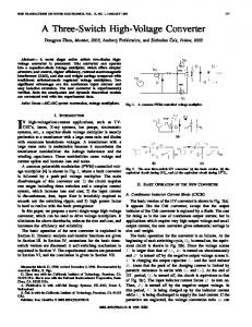
Equations (1)–(3) are sufficient to determine from known voltage, but it remains to calculate electromagnetic torque. It is common in the analysis of electric machines to utilize coenergy techniques. For the SRM, this procedure yields (4) In a number of applications, (4) is sufficiently accurate to model the machine. Since accuracy of the torque is of utmost importance in the analysis to follow, a direct method of torque calculation is preferred. This relies on using the following functional relationship: (5) Fig. 1. Cross-sectional diagram of 8/6 switched reluctance machine.
application is that the four-phase SRM drive can be converted, in a mathematical sense, to an equivalent two-phase drive. Simulated and experimental results are used to demonstrate the optimization method and how the multiple reference frame synchronous estimator/regulator ensures optimality in practice. II. SWITCHED RELUCTANCE MOTOR MODEL A cross-sectional diagram of a typical SRM is depicted in stator teeth, rotor teeth, and Fig. 1. The SRM has phases. It shall be assumed that the machine is balanced and symmetrical, mutual phase coupling is negligible, and that hysteresis and eddy currents are absent. The voltage equation can then be written as (1) , and are, respectively, the voltage, current, and where and flux linkage of the ’th phase where denotes the phase resistance. is depenAssuming there is no coupling between phases, . This dependence is nondent only on and rotor position, linear but it is periodic in rotor position. It is convenient to desuch that one pefine electrical rotor position as is the smallest interval within which periodicity exriod of ists. Herein, will be taken to be zero at an aligned position of , and is complicated phase 1. The relationship between and can be generally expressed as (2) where (3) The form of (3) assumes that if rotation is taken as positive in the clockwise sense as illustrated in Fig. 1, then the stator sequence in the counteeth are wound to have a 1, 2, 3, 4, 1, terclockwise direction. Activating the phases in sequence then gives clockwise rotation.
In (5), the function is determined from static torque data produced by finite element analysis, design data, or from physical measurement. Also note that (5) is particularly useful for the optimization procedure in the following section since it is stated directly in terms of the optimization variable, . While not apparent from (4)–(5), the torque is independent of the direction of the current. A periodic combination of sinusoids and polynomial terms can ensure the proper symmetry of and . A suitable form for can be determined by noting that at positions, , the torque the phase torque is zero. Furthermore, when must be zero. A suitable form for is then (6) The appropriate form of is then derivable from (4). Particularly, there is a ninety-degree shift in (7) and are determined by least-squares The coefficients fitting to data obtained from measurement or finite element anal, and represent the maxysis. The constants imum order of the functions considered in (6)–(7) and must be specified such that the error will be acceptably low. There is the notable disadvantage that for current outside the data set, these functions can exhibit unbounded, nonphysical behavior. This restricts the peak phase current in our analysis but presents little lack of generality since the peak current must be restricted already to ensure physical limitations of the motor and inverter are not exceeded. Other forms for and are certainly possible. For example, a popular form for is suggested in [10]–[12] that is relatively simple and behaves well regardless of current. The function in [10]–[12], however, was found to have insufficient accuracy for this application in the regions surrounding aligned rotor position and is more suitable for the real-time control application it was originally developed for. As an example, a 4 kW machine that has , and is considered herein, similar to the machine
78
IEEE TRANSACTIONS ON POWER ELECTRONICS, VOL. 17, NO. 1, JANUARY 2002
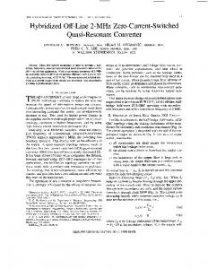
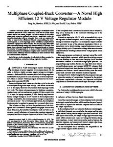
Fig. 4. Split-capacitor inverter for 8/6 switched reluctance drive. Fig. 2. Flux linkage versus current and rotor position for phase one.
so that it can be rapidly solved by commercially available optimization software. The objective is that a function is to be minimized (8)
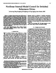
Fig. 3.
Torque versus current and rotor position for phase one.
depicted in Fig. 1. The torque data was obtained with static tests using an in-line torque sensor. Flux linkage versus current data was obtained by first locking the rotor and applying a step voltage, capturing the voltage and current waveforms with a digital oscilloscope, and then integrating (1) off-line to determine the flux-linkage. The procedure is then repeated at many other rotor positions. The least-squares fitting for has an average percent error of 0.94% over 500 data points. The fitting of has an average percent error of 1.98% over 546 data points. Figs. 2–3 depict plots of the flux linkage and torque relationships versus current and rotor position for phase 1, respectively. There are several inverters that can be used for four-phase machines [13]. The one chosen for this investigation is depicted in Fig. 4 and was chosen because the 4 kW machine was manufactured with a common phase connection. This inverter restricts . In the experimental appathe applied phase voltage to ratus, the IGBT and diodes are rated at 50 A and 1200 V and the capacitors are 1000 F. Each phase is equipped with a current sensor, which can be used for fault protection as well as control.
III. DEVELOPMENT OF OPTIMIZED CURRENT COMMANDS This section sets forth the method for calculating the optimal currents for the SRM. Due to the extreme nonlinearity of the torque and flux linkage equations, only a numerical approach can be taken. The main effort lies in formulating the problem
is the square of the rms phase current, and is where the square of the rms torque ripple. Three general modes are considered based on (8). Minimum current (MC) mode occurs when the positive constant takes on a very high value. Minimum ripple (MR) modes occurs when is near zero. Minimum current-minimum ripple (MCMR) mode is represented when takes on an intermediate value chosen by the designer. This represents a compromise for situations in which either MC or MR modes are too restrictive. Certainly, more complicated versions of (8) could be composed if it were desired to minimize total motor losses. Since relatively lowspeed operation is considered herein, the resistive losses dominate and (8) will suffice. If so desired, the analyst could employ a number of techniques to add closed-form iron loss terms to (8) without changing any other aspect of the analysis. The remainder of this section is devoted to developing the formulas necessary for applying the optimization routine to (8). For a given torque and speed, the phase currents are periodic in . Taking the current to be balanced and symmetrical (9) holds for each . Therefore, it is sufficient to determine and then apply (9) to determine the other three currents. Since the SRM is operated such that any phase current is either positive or zero, an important simplification can be achieved at the outset. It can be observed from (9) that
(10) and produce torque It can be shown that for any given in opposite directions. The same relationship holds for phases is positive, should 2 and 4. This suggests that while be zero, and vice versa. In order to simplify the analysis, it is convenient to define
(11)
CHAPMAN AND SUDHOFF: OPTIMIZED CURRENT WAVEFORMS
79
Since and are never simultaneously nonzero, all of the and . That is, the four relevant information is contained in phase currents can be found from
(12) where a similar relationship holds for . The definitions (11)–(12) achieve a reduction of currents to be considered from four to two, but also introduce a further simpliand are half-wave symmetric since fication. In particular, it can be derived from (10)–(11) that
Now, the rms current of phase 1 can be minimized by minimizing (17) and the problem becomes to determine the optimal vector (16). Since the currents are now explicit functions of , the and the vector , torque is now only a function of . Since for a given i.e., is constant, the torque is only steady-state operating point dependent on . This allows the straightforward calculation of the average torque as (18) and calculation of the rms torque ripple
(13) (19) Half-wave symmetry implies that there are only odd harmonics present in the waveform, while the original phase currents, , generally contain odd and even harmonics including a dc component. Thus the definitions (11)–(12) also reduce the order of harmonics that need to be considered. This is important from a computational standpoint and will make the optimized currents more amenable to the current controller presented in the next section. and for optiThe problem now becomes to calculate mality. To this end, note that the rms current of phase 1 is equal to the rms current of all the phases by (9). Thus, minimizing the rms current of phase 1 is sufficient for minimizing the rms current for all the phases. It can be shown that (14) is the squared rms value of the phase 1 current. This suggests is sufficient for minimizing that minimizing the rms value of the rms value of . For a given torque command, the currents are periodic with rotor position and therefore may be expressed in the form
(15) where and are constants associated with the Fourier series is the set of harmonics considered. and Thus, all of the necessary information for constructing the phase currents is contained in the coefficients and . As the torque and change, command changes in response to the plant, but (15) still holds. It is useful to express the set of coefficients in vector form as (16) wherein the rms value of combining (16) and (14)
can now be compactly expressed by
(17)
Due to limited inverter voltage, it is also important to consider the voltage required for a given current. First the chain rule is used to rewrite (1) as (20) . where The derivative of with respect to is required to evaluate is easily computed from (15). Since (20). The derivative of and share the relationship stated in (12), it is true that (21) where ‘sgn’ takes the algebraic sign of its argument and . The partial derivatives in (20) are available from straightforward differentiation of (2). For a given rotor speed, then (20) and . The SRM utilizes can be evaluated for any given both positive and negative voltage, where the maximum voltage and the minimum is , assuming the caavailable is pacitor voltages are well balanced (see Fig. 4). Therefore (22) The complexity of (5), (7), (15) prohibit analytical calculation of (17)–(19), (22), so these quantities are calculated numerically. This constraint accommodates the increasing back emf with speed. The speed at which this constraint cannot be achieved must be determined numerically, although waveshaping is theoretically possible at any speed provided the torque is low enough. The speed for waveshaping is more practically limited by switching frequency capability than by shortcomings of the above formulation. Sequential quadratic programming [14] was used to solve the optimization problem. The method utilizes an objective function , as well as a constraint vector . To guarantee than the voltage limit is not exceeded, that the average torque command is exactly achieved, and that the maximum and minimum of the
80
IEEE TRANSACTIONS ON POWER ELECTRONICS, VOL. 17, NO. 1, JANUARY 2002
phase current is not exceeded, the appropriate constraint vector is
(23)
is the dc voltage available for a single phase and where is the commanded average torque. The maximum peak current . Two constraints are required for the average allowed is torque in order to achieve one equality constraint. The minimum current constraint is necessary since negative current cannot be realized in practice. Of course, this is only one example of the possible set of constraints. Elements may be added or removed from (23) as desired. In summary, (8) is to be minimized subject to the constraint of (23). The quantities in (8), (23) can be calculated with an input of a desired average torque, a nominal rotor speed, a peak current constraint, and a dc voltage constraint. The algorithm will vary the vector (16) until an optimal solution is reached or the number of maximum iterations is exceeded. The output is an optimal vector of Fourier coefficients, , in the form of (16). The procedure set forth herein to calculate the optimal current waveform is only appropriate for use in an off-line fashion. In an actual drive the torque command and speed vary in response to the system in which the drive is embedded. In order to accommodate this, the range of speed and torque commands are discretized, and a set of current waveform coefficients is calculated off-line and stored for each point in the discretization. In particular, each coefficient is stored as part of a two dimensional array whose indices correspond to speed and torque command. These tables are interpolated on-line to come up with instantaneous values of coefficients based on current operating conditions. If the look-up table is large enough to achieve sufficient resolution, interpolation is not required. Note that since there will typically only be four to eight coefficients for a given operating point, the storage requirement are quite modest. IV. IMPLEMENTING THE OPTIMAL CURRENT COMMAND The method of the previous section is adequate for determining the desired optimized waveform, but it is another matter to ensure that the waveforms will be achieved in practice. A straightforward method to achieve these waveforms is to use a hysteresis or delta modulator. However, these regulators can exhibit significant error in achieving the desired current. In this section, a feedback regulator is presented that ensures precise realization of the desired current. In particular, the multiple reference frame synchronous estimator/regulator (MRFSER), previously set forth in the context of three-phase permanent-magnet synchronous machine drives [8] is used to ensure that the commanded currents are precisely achieved. The MRFSER consists of an estimator that dynamically decomposes the harmonic content of the waveforms and a regulator that drives the specified fundamental and harmonics to their desired values.
Fig. 5. Switched reluctance drive system with optimized current waveforms and multiple reference frame controller.
The estimator portion of the MRFSER extracts the low-frequency features of the current waveform and filters out the switching-frequency ripple. From (15), the low frequency components of the current may be expressed (24) where (25) and is the set of odd integers representing the harmonics conand are computed from the measured sidered. In (24), phase current and (10). It is the objective of the estimator to recover the coefficients and . The following control law, when implemented for each , produces the estimates as desired
(26)
is the estimator gain, and is the Laplace operator, where and ‘ ’ designates the estimated value. Notice in (26) that the estimate of the ’th harmonic depends on the estimates of all the other harmonic present. The interconnection implicit in (26) is critical to rapid, nonoscillatory convergence. Full development and proof of concept of (26) is given in [8], [9]. The regulator portion of the MRFSER is similar in principle to the industry standard synchronous current regulator [15], [16], which is designed to exactly obtain the desired fundamental component. However, the MRFSER uses multiple synchronous reference frames in order to guarantee that the fundamental and harmonics are precisely attained. The MRFSER operates separately on each specified harmonic of the current, driving each component to its desired steady-state value. In order to drive the estimated current waveform, and hence the actual current waveform, to the desired value the following regulator control is used for each (27) is the controller gain. In (27), a modified current comwhere mand (denoted by the ) is produced based on commanded cur-
CHAPMAN AND SUDHOFF: OPTIMIZED CURRENT WAVEFORMS
81
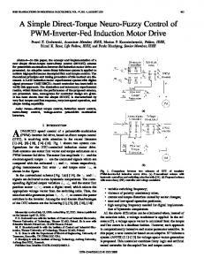
Fig. 6. Optimized phase-one currents for MC, MR, and MCMR (a = 1) with RMS values indicated. Fig. 8. Simulated electromagnetic torque and phase-one current for a fixed-angle switching scheme.
Fig. 7. Optimized torque for MC, MR, and MCMR (a = 1) Modes with RMS ripple values indicated.
rents and which were chosen based on the method in the previous section as well as their estimated values. A hysteresis or delta modulator requires an input of the actual phase current commanded which is calculated using (28) and to the four phase Then, (11) can be used to convert current commands that are the inputs to a hysteresis or delta modulator. A schematic of the drive control with the MRFSER is depicted in Fig. 5. The specific roles of the optimal command cur, measured current, and the modified command currents rent , are explicitly indicated. In the steady state, the modified commands will have adjusted so that the actual current precisely attains the desired optimal command. V. EXPERIMENTAL VALIDATION OF PROPOSED CONTROL In this section, experimental studies are presented to demonstrate the validity of the proposed controller. The 4 kW 8/6 motor (parameters are listed in the Appendix—the extraction method is more explained in more detail in [9]) with inverter de-
picted in Fig. 4 is the subject of these examples. For a set-point of 400 rpm average speed, 15 Nm average torque, and 600 V total bus voltage, the optimization procedure was performed modes. The set must for MC, MR, and MCMR be specified before the final results can be analyzed. Setting was found to give a good compromise between desired performance and complexity. While omitted here for brevity, it was shown in [9] that using more harmonics only slightly improved rms current and torque ripple, but using fewer drastically degraded the results. This choice of is not necessarily the best for all machines one might consider, but seemed to be reasonable for the test machine. Figs. 6 and 7 depict the optimal current waveforms and the corresponding torque waveforms, respectively, for MC, MR, and MCMR modes. The commanded torque is 15 Nm, the total bus voltage is 600 V, and the speed is 400 rpm. In the experimental set-up, a dynamometer regulates the speed. As can be observed, MR mode exhibits significantly lower torque ripple than either MC or MCMR mode. MC mode has significantly lower rms current, but comparatively very high torque ripple. MCMR mode has a reasonable compromise of both. Since torque ripple is of utmost concern for SRM’s operating at low speeds, MR mode will be considered for the remainder of the study. For the sake of comparison, a plot of simulated phase current and electromagnetic torque is shown in Fig. 8 wherein a typical fixed-angle switching scheme was used (no waveshaping). The turn-on and turn-off angles were selected judiciously in order to approximately minimize torque ripple. It is evident that the rms torque ripple, rms current (10.2 A), and peak current, is much higher when MR optimization is not applied. If the speed is low enough that the losses are dominated by phase resistance, the power lost reduces from 270 W to 100 W, so the efficiency increases from about 57% to 84%. The dramatic increase comes from the added flexibility of waveshaping over fixed angle firing in minimizing torque ripple. The same motivation is suggested in [1]–[6]. The drive was operated both with and without the MRFSER active to observe the effect on the torque spectrum with 4 kHz delta modulation. Added torque ripple generally exists without
82
IEEE TRANSACTIONS ON POWER ELECTRONICS, VOL. 17, NO. 1, JANUARY 2002
PARAMETERS
TABLE I TORQUE EQUATION SRM MACHINE FOR
OF
TABLE II PARAMETERS FOR FLUX LINKAGE EQUATION OF SRM MACHINE
Fig. 9. Commanded and experimentally measured phase-one current with MRFSER active (top) and inactive (bottom).
Fig. 10. Experimentally measured torque spectrums for MR mode with MRFSER inactive (top) and active (bottom).
the MRFSER active due to error in regulating the current. This phenomenon is portrayed in the time domain in Fig. 9 wherein the commanded and measured current are overlaid for both the MRFSER active and inactive. Note that the measured current is shown with the switching frequency ripple removed. The lowfrequency components were extracted off line so that they could be clearly compared to the commanded waveform. From Fig. 9, it is apparent that near the peak of the command, the convergence is weak without the MRFSER active. This is particularly troublesome considering that near the peak, the phase is delivering the greatest amount of torque. The result is not only in increased ripple, but also reduced average torque. By using the measured current from Fig. 9, a quasimeasured torque can be constructed from which spectrums can be computed. This was done to create Fig. 10, wherein the ‘measured’ torque spectrums show that there is enough error in the current to give significant extra torque ripple, particularly at 240 Hz. Future work should include acoustic data, as torque ripple can influence au-
dible noise significantly, however, the appropriate chamber and instrumentation were not available. From this analysis it can be concluded that the use of a deltamodulated regulator alone is not necessarily sufficient to produce the desired optimality of performance. A hysteresis modulator, while different, would also cause some error in the current and introduce several well-documented disadvantages [7]. In either case, the current regulation can be improved by increasing in hysteresis the switching frequency (e.g., by decreasing control or increasing clock frequency in delta modulation), but this increases switching losses, heat sink requirements, and electromagnetic compatibility problems, yet may still not reduce the error to an acceptable level. The problem is more noticeable in large drives where it is difficult to obtain high switching frequency. The designer must carefully weigh many alternatives when implementing an SRM drive that has optimized current waveforms. The MRFSER presents the designer with a new alternative that can eliminate the dependence on switching frequency and ensure precise tracking. It should be noted that the MRFSER is completely implemented in software and only introduces slightly more stringent demands on the microcontroller (memory and processing speed) but requires no hardware that does not otherwise exist in a current-regulated SRM drive. Furthermore, the MRFSER will guarantee convergence of the optimized currents, which is particularly useful for certain high-performance applications. At this point, it is appropriate to comment on some finer points of the physical implementation. The control is implemented with a 40 MHz fixed point DSP card that has an analog I/O daughterboard with appropriate A/D circuitry. With the control coded, the loop time was approximately 100 s. The integrators are approximate discretely by the trapezoidal rule. A 12-bit optical encoder is used to provide position feedback. Look-up tables for cosine and sine terms were produced as preprocessing and to reduce loop time. It is noteworthy that from just , all the other trigonometric functions required can be produced by algebraic identities. During development of the system, key issues that were resolved included balancing of the
CHAPMAN AND SUDHOFF: OPTIMIZED CURRENT WAVEFORMS
current sensing and data conversion, as well as achieving simultaneous sampling of the data. VI. CONCLUSION This work has presented a new technique of generating optimal current commands for SRM drives. Unlike previous work, the currents are represented as a small set of Fourier coefficients, rather than as a large set of discrete points. This reduces memory requirements and facilitates effective interpolation. It was shown that standard current regulation techniques do not necessarily produce actual currents that satisfactorily track their optimized commands. To remedy this, a multiple reference frame controller was presented that ensures steady-state convergence of the current waveforms. The experimental results show that failure to achieve the waveforms exactly can result in unwanted torque ripple and incorrect average torque, which is prohibitive in higher performance applications that current-regulated SRM drives are designed for. APPENDIX The machine parameters are shown in Tables I and II. The phase resistance is 0.65 .
83
[6] J. W. Finch, H. M. B. Metwally, and M. R. Harris, “Switched reluctance motor excitation current: Scope for improvement,” in Proc. PEVD Conf., 1986, pp. 196–199. [7] B. K. Bose, Ed., Power Electronics and Variable Frequency Drives. New York: IEEE Press, 1997. [8] P. L. Chapman and S. D. Sudhoff, “A multiple reference frame synchronous estimator/regulator,” IEEE Trans. Energy Conv., vol. 15, pp. 197–202, June 2000. [9] P. L. Chapman, “Formulation and implementation of optimal control strategies for variable waveshape drives,” Ph.D. thesis, Purdue Univ., West Lafayette, IN, Aug. 2000. [10] K. Russa, I. Husain, and M. E. Elbuluk, “Torque-ripple minimization in switched reluctance machines over a wide speed range,” IEEE Trans. Ind. Applicat., vol. 34, pp. 1105–1112, Sept./Oct. 1998. [11] M. Ilic-Spong, R. Marino, S. M. Peresada, and D. G. Taylor, “Feedback linearizing control of switched reluctance motors,” IEEE Trans. Automat. Contr., vol. AC-32, pp. 371–379, May 1987. [12] M. Ilic-Spong, T. J. E. Miller, S. R. Macminn, and J. S. Thorp, “Instantaneous torque control of electric motor drives,” IEEE Trans. Power Electron., vol. PE-2, pp. 55–61, Jan. 1987. [13] R. M. Davis, W. F. Ray, and R. J. Blake, “Inverter drive for switched reluctance motor. Circuits and component ratings,” Proc. Inst. Elect. Eng. B, vol. 128, pp. 126–136, Mar. 1981. [14] M. J. D. Powell, “A fast algorithm for nonlinearly constrained optimization calculation,” in Proc. 1977 Dundee Conf. Numer. Anal., June 1977. [15] C. D. Schauder and R. Caddy, “Current control of voltage-source inverters for fast four-quadrant drive performance,” IEEE Trans. Ind. Applicat., vol. IA-18, pp. 163–171, Mar./Apr. 1982. [16] T. M. Rowan and R. J. Kerkman, “A new synchronous current regulator and an analysis of current-regulated inverters,” IEEE Trans. Ind. Applicat., vol. IA-22, pp. 678–690, 1986.
ACKNOWLEDGMENT The authors would like to thank C.-M. Ong, Purdue University, for allowing the use of his test motor for this work, and Todd Walls, Emerson Electric Co., for donating a PM motor that was used in some experiments. REFERENCES [1] I. Husain and M. Ehsani, “Torque ripple minimization in switched reluctance motor drives by PWM current control,” IEEE Trans. Power Electron., vol. 11, pp. 83–88, Jan. 1996. [2] A. M. Stankovic, G. Tadmor, and Z. J. Coric, “Low torque ripple control of current-fed switched reluctance motors,” in Proc. 1996 Ind. Applicat. Conf., vol. 1, 1996, pp. 84–91. [3] H. C. Lovatt and J. M. Stephenson, “Computer-optimized current waveforms for switched-reluctance motors,” Proc. Inst. Elect. Eng., vol. 141, pp. 45–51, Mar. 1994. [4] J. Y. Le Chenadec, B. Multon, and S. Hassine, “Current feeding of switched reluctance motor: Optimization of the current wave form to minimize the torque ripple,” in Proc. IMACS-TC1 4th Int. Conf., July 1993, pp. 267–272. [5] G. Dunlop, “A switched reluctance motor drive with zero torque ripple and a constant inverter bus current,” in Proc. Inst. Mech. Eng., vol. 208, 1994, pp. 61–68.
Patrick L. Chapman (M’93) received the B.S. (with honors) and M.S. degrees from the University of Missouri, Rolla, in 1996 and 1997, respectively, and the Ph.D. degree afrom Purdue University, West Lafayette, IN, in 2000. He is an Assistant Professor at the University of Illinois, Urbana-Champaign, which he joined in 2000. He conducts research in power electronics and electric drives, with specific interests in integrated power circuits, advanced drive control schemes, and modeling of machinery.
Scott D. Sudhoff (M’91) received the B.S. (with highest distinction), M.S., and Ph.D. degrees in electrical engineering from Purdue University, West Lafayette, IN, in 1988, 1989, and 1991, respectively. From 1991 to 1993, he served as a Consultant in aerospace power and actuation systems and as a Visiting Faculty at Purdue University. From 1993 to 1997, he served as a Faculty Member at the University of Missouri, Rolla, and in 1997 he joined the faculty of Purdue University. His interests include electric machines, power electronics, and marine and aerospace power systems. He has two patents, and has published over 40 journal and transactions papers in these areas, including two prize papers.