4th International Conference from Scientific Computing to Computational Engineering 4th IC-SCCE Athens, 7-10 July, 2010 © IC-SCCE
POWER SYSTEMS AND MODERN WIND POWER TECHNOLOGY – MODELING AND CONTROL ISSUES Ioannis D. Margaris1 and Nikolaos D. Hatziargyriou1,* 1
Electric Energy Systems Lab. School of Electrical and Computer Engineering National Technical University of Athens 15780, Zografou, Athens, Greece e-mail:
[email protected],
[email protected] *
Public Power Corporation S.A., Athens, Greece
Keywords: Power system modeling, Wind turbine technology. Abstract. The large-scale integration of wind power into modern power systems has set novel challenges for the system operators. The special features of wind turbine technology make security issues rather critical and operation of wind farms as conventional power plants is becoming a necessity as wind turbines replace conventional units in the production side. This paper analyzes the results produced with sophisticated models for three major wind turbine types – namely Doubly Fed Induction Generator (DFIG), Permanent Magnet Synchronous Generator (PMSG) and Active Stall Induction Generator (ASIG). Mathematical modelling of wind farms, conventional units and all other crucial components of power systems is necessary to simulate the behaviour and operation of the system during variable wind profiles but also during faults in the grid. The paper covers a wide range of investigations, including power fluctuations and fault ride-through issues. Results from simulations with stochastic wind speed are presented and discussed. The results prove that ancillary services provided by wind farms in the future can ensure secure and reliable operation of power systems despite the high levels of penetration. The evolution of modern wind turbines is a story of engineering and scientific skill, coupled with a strong computational capability. State of the art modeling considerations are presented in the paper based on dedicated simulation platforms used nowadays by research institutes and power industry. 1 INTRODUCTION A decade ago, most grid codes considered wind farms as small size dispersed generation and therefore did not require wind turbines to support the power system during transients following grid disturbances. Wind turbines could be disconnected when abnormal grid voltage behavior was detected. The constantly increasing penetration of wind power in the power systems over the last years posed serious concerns regarding the sudden loss of power during grid faults, which could be caused by wind turbines´ disconnection, leading possibly to further severe frequency and/or voltage instability. Nowadays grid codes include a wide range of technical requirements that wind farms have to fulfill, [1]. However, in most non interconnected power systems wind power is still considered as dispersed energy and no specific requirements are defined. Ancillary services provided by wind turbines, like fault ride through capability (FRT), are investigated in this article through detailed modelling for all different components of the system. Before wind power penetration limits are expanded in power systems with limited inertia, dynamic security issues have to be carefully investigated. Among the issues studied, power fluctuations resulting from wind speed variations are simulated to analyze the effect on the system frequency. For the investigations the study case of the Rhodes power system was used. The simulation platform, which was developed, includes three types of conventional generators – gas, diesel and steam units – and three types of wind turbines – Active Stall Induction generator (ASIG), Doubly Fed Induction generator (DFIG) and Permanent Magnet Synchronous generator (PMSG) wind turbines. The response of conventional units, the under/over voltage and frequency protection system, the load dependency on frequency and voltage and the wind turbines’ response during events that affect system frequency are some of the key aspects that have to be modelled in detail.
Ioannis D. Margaris, and Nikolaos D. Hatziargyriou
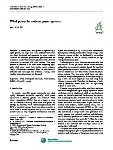
2 POWER SYSTEM MODELING The basic characteristics of Rhodes power system in the reference year 2012 are summarized in Table 1 in the Appendix. The system includes two power plants and five wind farms. Power system simulation studies for 2012 were based on modified operational data and additional generating units and wind farms, which are expected to be online by the year of study, 2012, [2]. The load scenario, which is presented in this paper, is the maximum wind power penetration scenario (34 % of the load demand). This scenario refers to the winter season, when wind power is significant and load is relatively low. The system inertia under these conditions is restricted, as not so many conventional units participate in the production. Details regarding the modeling of the conventional generating units as well as the wind farms can be found in [3]. Three types of conventional units are included in the model: diesel, gas and steam plants. The controllers applied in these units were designed based on built-in standard models available in Power Factory, [4]. The parameters, validated both in Matlab and PSS/E software packages, are presented in [5]. The dynamic models for the system loads connected to Medium Voltage (MV) feeders are using the constant impedance assumption, [6]. Three wind turbine technologies are considered, namely Doubly Fed Induction Generator (DFIG), Permanent Magnet Synchronous Generator (PMSG) and Active Stall Induction Generator (ASIG) based wind turbines, see Figure 1. The installed capacity and type of wind turbine technology used in each wind farm are presented in Table 2 in the Appendix. The aggregation method used to model the wind farms in the system reduces the complexity without compromising the accuracy of the simulation results, [7,8]. Aerodynamics SCIG
Drive train-Gear
Ps
Grid
Transformer
Soft-starter
Capacitor Bank
Aerodynamics Drive train-Gear
WRIG
Ps
Grid
Transformer
Ptot Pr crowbar
Control system Rotor side converter
Grid side converter
Aerodynamics
Gearless
PMSG P stator
chopper
Generator side converter
Pgrid
Transformer
Grid
Grid side converter
Control System
Figure 1. System configuration for three wind turbine schemes: ASIG, DFIG and PMSG wind turbines The model for the ASIG wind turbine includes sub-models for aerodynamics, mechanical components and the squirrel cage induction generator. A two-mass model is used to represent the drive train and the pitch controller controls the active power production through the adjustment of the pitch angle, [9]. The model for the wind farms with DFIG wind turbines is described in detail in [10]. The DFIG system is essentially a wound rotor induction generator with slip rings, with the stator directly connected to the grid and with the rotor interfaced through a back-to-back partial-scale power converter, [11]. The control configuration for the DFIG scheme is given in Figure 2. The rotor side converter regulates the active and reactive power implementing the maximum power point tracking strategy and controlling either the power factor or the grid voltage respectively. The grid side converter controls the DC-link voltage and the reactive power exchanged with the grid. Under normal operation this converter is operated at unity power factor. As illustrated in the following figure, the control
Ioannis D. Margaris, and Nikolaos D. Hatziargyriou
includes two control loops. The slower one controlling active or reactive power and DC-link voltage and the inner fast current loop which provides the reference signals for the voltages imposed to the PWM control of the converters. ias , iβ s
υas , υbs DFIG
[T]
ias , ibs
υas , υβ s Ψ s
abc →SRF
ψ as ,ψ β s
θ sfrf
∠ψ s
d dt
U s
ωs υa,gsc ,υb,gsc
[T]
υa ,υβ
∠U gsc
abc → SRF
RSC
U r
[T]
PWM
abc →SRF
υarref ,υbrref ,υcrref
ωs
abc → SRF
-
[T]
+
SRF → SFRF
θgvrf ia ,iβ
[T] SRF → GVRF
ref υarref ,υβr
ref ref ref υa,gsc ,υb,gsc ,υc,gsc
SRF → abc
υaref ,υβref
[T]
idr
id,gsc
[T]
PWM
SRF → abc
iar , iβ r s
[T]
iq,gsc
[T]
-
+
Rf
iar , ibr
d dt
ωr
Lf
U dc,link
U dc,link
θr
ia,gsc ,ib,gsc
GSC
[T]
SFRF → SRF GVRF → SRF
iqr
θ sfrf Active Power Control ref Pgrid +
ωr Maximum power point tracking
-
PI
iqrref
+
PI
iqr
meas grid
P
υqrref
meas Qgsc +
Reactive power control
-
ref iq,gsc +
PI
PI
iq ,gsc
ref gsc
Q
ref υq,gsc
Reactive Power Control
Power Factor Regulation
ref Qgrid +
Voltage control
Reactive power scheme selection
meas grid
Q
PI
idrref
+
PI
idr
υdrref
DC voltage control
meas U dc,link +
ref U dc,link
ref id,gsc +
PI
PI
id,gsc
ref υd,gsc
Figure 2. Control scheme for the generator side converter and grid side converter of the DFIG scheme The model for the PMSG wind turbines includes the mechanical subsystem (i.e. aerodynamics, gearless drive-train and pitch angle control) and the electrical components (i.e. multi-pole PMSG with a full-scale frequency converter and its control). The converter system consists of a back-to-back voltage source converter controlled by IGBT switches, [12,13]. The generator side converter controls the stator voltage and the DC-link voltage while the grid side converter regulates the active and reactive power control similar to the way explained above about the DFIG scheme. The control diagram of the back-to-back converter is illustrated in Figure 3. ωr
d dt
PMSG
U f
Us
θr
Lf
Rf
U gsc
Cdc
U dc,link
Generator voltage regulator
U sref + -
iqsref +
PI
meas U dc,link +
U
-
cmqs
iqs
Us
DC voltage control
PI
-
Generator side converter control
idsref +
PI
PI
-
ref dc,link
cmds
ids
Active power control ref grid
P
ωr Maximum power point tracking
+ -
PI
Power factor regulation
ref Qgsc -
+
Reactive power scheme selection
meas Qgsc
-
PI
cmd,gsc
id,gsc
meas Pgrid
Grid side converter control
Reactive power control
Voltage control
ref id,gsc +
PI
ref iq,gsc +
-
PI
cmq,gsc
iq,gsc
Figure 3. Control scheme for the generator side converter and grid side converter of the PMSG scheme
3 POWER FLUCTUATIONS Wind speed fluctuations may cause significant wind power fluctuations, although different wind turbine technologies respond more or less soft to the wind speed variations. The summed power fluctuation from all the
Ioannis D. Margaris, and Nikolaos D. Hatziargyriou
wind farms is the factor which influences the frequency control in the system. In this study, the Correlated Wind (CorWind) speed simulation tool has been applied to simulate simultaneous wind speed time series at all the wind farm locations. This tool has been developed and validated, based on a substantial database with measurements acquired on land as well as offshore locations, [14,15]. In the maximum wind power penetration scenario, presented in this paper, the fluctuations in the wind may have serious impact on the power system operation due to low system inertia. The system inertia is defined as the total angular momentum, thus the sum of the angular momenta of the rotating masses in the system i.e. generators and spinning loads. Figure 4 illustrates the wind time series, which have been applied to the wind farms. Due to the wind fluctuations, the system frequency varies between 50 Hz and 50.25 Hz, which is considered safe for the system operation (see Figure 5). Although the wind speeds in each wind farm may have sudden changes the overall response of the system is satisfactory, and the power outputs from the wind farms seem to counteract each other in the frequency impact. The emergency rate of power undertaken by the conventional units is sufficient to overcome the rapid active power fluctuations produced by the wind farms on the island. 11.5
Wind Speed (m/s)
11 10.5
WFB1 WFB2 WFA1 WFA2 WFC
10 9.5 9 8.5 8 0
100
200
300
Time (sec)
400
500
600
System Frequency (Hz)
Figure 4. Wind time series applied to the wind farms 50.3
50.2
50.1
50
49.9 0
100
200
300
Time (sec)
400
500
600
Figure 5. System frequency for wind time series Despite the fast wind fluctuations, no load is cut off and the frequency is varying in a quite narrow range around nominal 50 Hz. The frequency fluctuations resulting from the wind speed fluctuations are not considered high enough to pose security questions for the power system.
4
FAULT RIDE THROUGH CAPABILITY
In case of sudden voltage drop at a grid fault instant, the wind turbines are asked nowadays to stay online and sometimes provide also with reactive power supporting the voltage. Depending on the wind turbine configuration, different control methods have to be implemented in order to ensure uninterrupted operation of the wind farms and prevent further production loss. Figure 6 shows the voltage dips simulated at the Points of Common Coupling (PCC) for each wind farm in case of a three phase fault in a transmission line close to the wind farms.
Voltages at PCC of WFs (p.u.)
Ioannis D. Margaris, and Nikolaos D. Hatziargyriou
1 0.8
WFB1 and WFA2 WFB2 and WFA1 WFC
0.6 0.4 0.2 0
1
1.2
1.4
Time (sec)
1.6
1.8
2
Figure 6. Voltage dips for a three-phase fault The method of power reduction at the instant of a fault at the grid was implemented for the ASIG wind turbine, [16]. An auxiliary control system substitutes the normal power controller of the wind turbine, which ramps down the mechanical power of the rotor. The restoration of the normal operation is ensured as soon as the voltage at the Point of Common Coupling (PCC) of the wind farm is re-established. Figures 7 and 8 illustrate the behavior of ASWG wind turbine during the fault. After the clearance of the fault, the active power may still be reduced for a few seconds. During the voltage drop, the active power delivered by the generator has to be reduced in order to make the turbine able to ride through the fault preventing possible rotor acceleration. 12
Grid Power (MW)
10 8 6 4 2 0 -2 0
5
10
Time (sec)
15
Figure 7. Active power during the fault for a wind farm equipped with ASIG wind turbines Compared to the sensitive power electronics of variable speed wind turbines, the thermal constants of the induction generator are quite high and the need for protection is reduced despite the high inrush currents, which occur during the fault. The rotor speed of the ASIG wind turbine reflects the power system frequency behavior during the fault (see also Figure 13). When the fault occurs, the speed is initially increased due to the acceleration of the conventional generators and afterwards drops below nominal value. Generator Speed (pu)
1.04 1.03 1.02 1.01 1 0.99 0.98 0.97 0
5
10
Time (sec)
15
Figure 8. Generator speed during the fault for a ASIG wind turbine The DFIG configuration requires advanced protection system due to the high inrush stator and rotor currents during grid faults. The rotor side converter is bypassed through the so called “crowbar”. The grid-side converter is not blocked at a grid fault and continues its operation as a STATCOM. The controllability is thus improved providing the DFIG with grid voltage support in uninterrupted operation during the transient instant, [17]. The voltage control is also activated in the rotor side converter control system, thus the wind farm manages to provide with additional reactive power supporting the grid voltage. The response of the DFIG wind turbines in WFA1 during the fault is illustrated in Figures 9 and 10 with or without damping controller. The active power corresponds to the whole wind farm (WFA1).
Ioannis D. Margaris, and Nikolaos D. Hatziargyriou 10
Grid Power (MW)
8 6 4 2 0 0
2
4
6
Time (sec)
8
10
12
Figure 9. Active power during the fault for wind farm with DFIG wind turbines – solid line, with damping controller, dashed line, without damping controller The active power delivered by the wind turbine is reduced due to the sudden drop of the voltage, which leads to drop in the stator and rotor flux. The drive train is acting as torsion spring and gets untwisted during fault. The mechanical torque drops slower than the electromagnetic torque and therefore the generator starts to accelerate, see Figure 10. The crowbar protection system is activated due to the high inrush currents. The rotor side converter (RSC) is blocked and the generator behaves as a conventional squirrel cage induction generator. The damping controller acts directly on the active power reference signal, [11]. This controller damps actively the torsional excitations in the drive train system following the grid fault. In case these oscillations remain undamped, the protection system could be triggered and lead to disconnection of the wind turbine to prevent further mechanical stresses. Generator Speed (pu)
1.1
1.05
1
0.95 0
2
4
6
Time (sec)
8
10
12
Figure 10. Generator speed during the fault for DFIG wind turbine – solid line, with damping controller, dashed line, without damping controller PMSG wind turbines can in principle easily accomplish fault ride-through and support the grid during faults due to the presence of the full scale converter. The generator side converter maintains the DC-link voltage around the nominal value while the grid side converter cannot deliver the expected active power during the low voltage at the grid fault instant. The surplus energy is consumed in a resistance through the operation of an additional chopper introduced in the DC-link. The addition of the chopper improves the overall response of the system, [18,19]. Figures 11 and 12 present the fault ride-through capability of the PMSG wind turbines in wind farm WFB2, with and without chopper.
Grid Power (MW)
4 3 2 1 0 -1 0
2
4
Time (sec)
6
8
Figure 11. Active power during the fault for wind farm with PMSG wind turbines – solid line, with chopper, dashed line, without chopper During the low voltage the grid-side converter cannot deliver to the grid the whole active power generated by
Ioannis D. Margaris, and Nikolaos D. Hatziargyriou
the generator. The imbalance between aerodynamic and electrical power during the fault causes the acceleration of the generator rotor and the drive train gets untwisted and oscillates. These oscillations are significantly reduced when a chopper is used, see Figure 12. Besides the faster damping of the oscillations, the chopper decreases the rotor accelerations following the fault, minimizing the mechanical stress of the wind turbine. Generator Speed (pu)
1 0.99 0.98 0.97 0.96 0.95 0.94 0.93 0
2
4
Time (sec)
6
8
Figure 12. Generator speed during the fault for a PMSG wind turbine – solid line, with chopper, dashed line, without chopper When the wind farms are not able to withstand the low voltage during the fault, they trip for protection reasons. In this case, the voltage dip leads to further wind power production loss resulting to larger frequency drop. In the load scenario under study in this paper the frequency of the system drops down to 47.6 Hz. The under-frequency protection system acts on the loads connected to the medium voltage substations and 65.5 % of the load, i.e. 54 MW, is immediately disconnected. On the contrary, when the wind farms are equipped with fault ride through capability, they are able to remain connected to the grid during fault, and the frequency minimum is 49.7 Hz, see Figure 13. The load shedding is thus totally avoided. The frequency stability as well as the load shedding are improved, making FRT crucial for the secure operation of the system. System frequency (Hz)
52 51 50 49 48 47 0
2
4
6
Time (sec)
8
10
Figure 13. System frequency during the fault – solid line, when wind farms are tripping due to low voltage, dashed line, when FRT is available and wind farms stay online
5
CONCLUSIONS
The main dynamic security issues of interconnected power systems under increasing wind power penetration were investigated in this paper. The model developed includes three types of conventional units and three types of wind turbines. The maximum wind power penetration scenario was presented and the under/over voltage and frequency protection system was added providing accurate results for the load shedding. The power fluctuations which follow wind speed variations were simulated using the CorWind wind speed simulation tool. The results showed that the frequency fluctuations resulting from the wind speed fluctuations are not considered high enough to pose security questions for the power system. However, the impact of wind variations is obvious in the system frequency and the correlation between wind speeds and system frequency has to be always investigated before reviewing the penetration levels. Increased wind power penetration does not only limit the ability of thermal plants to undertake power, but also limits inertia. The system operation was also investigated during low voltages conditions. In most non interconnected power systems due to lack of specific grid code the load shedding following fault events is often and severe. Wind farms are still allowed to trip when low voltage is detected at the Point of Common Coupling. In case of a short circuit at the grid the system encounters probable additional loss of production, leading to further stress in the dynamic security of the system in terms of frequency stability. When wind farms are equipped with fault ride through capability, the load shedding following frequency drops is decreased and the wind farms can resume
Ioannis D. Margaris, and Nikolaos D. Hatziargyriou
their operation contributing to the system security. DFIG and PMSG wind turbines can contribute to system stability by adjusting their reactive power production during low voltage instances. Advanced power electronic technology provides with sophisticated voltage control capabilities, similar to conventional power plants.
6
APPENDIX Rhodes power system Max Power Demand 233.1 (MW) Rated Thermal Power 322.9 (MW) Rated Wind Power 48.8 Generation (MW) Table 1. Basic characteristics of Rhodes power system in 2012
Wind Farm A1 Wind Farm A2 Wind Farm B1 Wind Farm B2 Wind Farm C
Wind Turbine Technology DFIG DFIG PMSG PMSG ASIG
Installed Capacity (MW) 11.05 5.95 18 3 11.7
Table 2. wind farms in Rhodes power system in 2012
Ioannis D. Margaris, and Nikolaos D. Hatziargyriou
REFERENCES [1] Ciupuliga, A.R., Gibescu, M., Fulli, G., Abbate, A.L. and Kling, W.L. (2009), “Grid Connection of Large Wind Power Plants: a European Overview”, 8th International Workshop on Large-Scale Integration of Wind Power into Power Systems as well as on Transmission Networks for Offshore Wind Farms, Bremen, Germany. [2] Margaris, I.D., Mantzaris, J.C., Karystianos, M.E., Tsouchnikas, A.I., Vournas C.D., Hatziargyriou, N.D. and Vitellas, I.C. (2009), “Methods for evaluating penetration levels of wind generation in autonomous systems”, IEEE PowerTech Conf., Bucharest, Romania. [3] Margaris, I.D., Hansen, A.D., Cutululis, N.A., Sørensen, P. and Hatziargyriou, N. (2010), “Impact of Wind Power in Autonomous Power Systems – Power Fluctuations – Modelling and Control Issues, submitted in Wind Energy (Wiley). [4] DIgSILENT GmbH (2006). DIgSILENT technical documentation -- PowerFactory. [5] Mantzaris, J., Karystianos, M. and Vournas C. (2008), “Comparison of Gas Turbine and Combined Cycle Models for System Stability Studies”, 6th Mediterranean. Conf. MedPower, Thessaloniki, Greece. [6] Cutsem, T.V. and Vournas, C. (1998), Voltage Stability of Electric Power Systems, Ed. Springer. [7] Akhmatov, V. (2003), Analysis of dynamic behavior of electric power systems with large amount of wind power, PhD thesis, Ørsted DTU, Denmark. [8] Poeller, M. and Achilles, S. (2003), “Aggregated wind park models for analyzing power system dynamics”, 4th international workshop on large-scale integration of wind power and transmission networks, Billund, Denmark, 10pp. [9] Jauch, C., Hansen, A.D., Sørensen, P. and Blaabjerg, F. (2004), “Simulation Model of an Active-stall Fixedspeed Wind Turbine Controller’, Wind Engineering, Vol. 28, no.2, pp. 177-195. [10] Hansen, A.D., Sørensen, P., Iov, F. and Blaabjerg, F. (2006) “Centralised power control of wind farm with doubly-fed induction generators”, Renewable Energy, Vol. 31, pp. 935-951. [11] Hansen, A.D., Michalke, G. (2007), “Fault ride-through capability of DFIG wind turbines’, Renewable Energy, Vol 32, pp. 1594-1610. [12] Hansen, M.H., Hansen, A.D., Larsen, T.J., Øye, S. and Sørensen, P. (2005), Control design for a pitchregulated variable speed wind turbine, Risø-R-1500 (EN), pp. 84. [13] Hansen, A.D. and Michalke, G. (2008), “Modeling and control of variable speed multi-pole PMSG wind turbine”, Wind Energy, Vol. 11(5), pp 537-554. [14] Sørensen, P., Cutululis, N.A., Vigueras-Rodriguez, A., Madsen, H., Pinson, P., Jensen, L.E., Hjerrild, J. and Donovan, M. (2008), “Modelling of power fluctuations from large offshore wind farms”, Wind Energy, Vol. 11, pp. 29-43. [15] Sørensen, P., Cutululis, N.A., Vigueras-Rodriguez, A., Jensen, L.E., Hjerrild, J., Donovan, M.H. and Madsen, H. (2007), “Power fluctuations from large wind farms”, IEEE Trans. Power Systems, Vol. 22, pp. 958-965. [16] Akhmatov, V., Knudsen, H., Nielsen, A.H., Pedersen, J.K. and Poulsen, N.K. (2003), “Modeling and transient stability of large wind farms”, Electrical Power and Energy Systems, Vol. 25, pp. 123-144. [17] Hansen, A.D., Michalke, G., Sørensen, P., Lund, T. and Iov, T. (2007), “Co-ordinated voltage control of DFIG wind turbines in uninterrupted operation during grid faults”, Wind Energy, Vol. 10 (1), pp.51-68. [18] Hansen, A.D. and Michalke, G. (2008), “Modelling and control of variable speed multi-pole PMSG wind turbine. Wind Energy, Vol. 11 (5), pp. 537-554. [19] Hansen, A.D. and Michalke, G. (2008), “Multi-pole PMSG wind turbines’ grid support capability in uninterrupted operation during grid faults’, IET Renewable Power Generation.