1
Preliminary Result of Unknown Object Manipulation Based on Reactive Control Qiang Li, Robert Haschke, Helge Ritter, and Bram Bolder
Abstract—In this paper, the authors proposed a novel reactive strategy to solve a unknown object local manipulation problem with an multifingered robot hand. In this method, the micro manipulation assumption is proposed and the object can be manipulated within the robot hand workspace without the active and explicit controlling about the rolling and sliding of the fingertips on the object. A 6 D.O.F reactive controller based on the hybrid of the contact force and the contact position feedback is developed. A three layer hierarchical control structure is employed to implement this manipulation strategy. The simulation experiment is run based on the physics engine-Vortex, to show the feasibility of this method. Keyword: Multifingered Hand, General Object Manipulation,Autonomous Exploration of Manual Interaction Space, Micro Manipulation
I. I NTRODUCTION It’s a challenge task for multifingered robot hand (the robot hand is used below if there is no special announcement) to dexterously manipulate one general object in the hand, because (1)The robot hand motion is defined in the high dimension and continuous state space (for example, one shadow hand[3] has 24 D.O.F including two D.O.F for wrist). It is extremly difficult to search and find the optimal state in real-time according to the manipulation task in such the tremendous state space. (2)The workspace of the robot hand is limited. This limitation requires the hand has the gaits control competence in order to realize the large scale object manipulation. The switch of gaits means the dimension of state space should be dynamic modification in the light of the contact status in the manipulaton context. Hence except for the continuous state there also needs the discrete events defined. (3)The limited prior knowledge and perception capability about the hand. The accurate kinematics and perception model of the robot hand’s end effector is unknown and the property (geometry, mass, etc.) of the objects is also unknown in prior. (4)The interaction and coordination between the fingers and the object need to be controlled. Unlike the grasp case–the most important issue is the stable grasp, the object manipulation, however, requires the control mode switch among stable grasp, rolling and sliding, and gaits switch between manipulation fingers and free fingers. Manuscript received August 10, 2011. Q. Li, R. Haschke and H. Ritter are with the Research Institute for Cognition and Robotics, Bielefeld University, Bielefeld, Germany
{qli,rhaschke,helge} @cor-lab.uni-bielefeld.de B. Bolder is with the Honda Research Institute Europe, Offenbach, Germany
[email protected]
The researchers in robot control community have made many contributions for the object manipulation with the robot hand. Theoretically they tried to develop the object manipulation kinematics and dynamics mathematics model[12]. Practically they tried to construct the robot hand to realize the object manipulation in the real physical environment[3].Such research has been the hot topic since 1980s’. At the beginning stage of the research the researchers prefered to use the structural interaction environment, for example,simple geometry object, simple mechanical robot hand and the simple contact model, because this kind of structure made it easier to develop the robot hand-object interaction mathematics model[7]. In this stage, the developing of the robot hand-object’s kinematic and dynamics model, the robot hand active rolling/sliding control[9], [10], the robot hand workspace analysis[6], the kinematics of contact[8] and the robot hand motion planning[12] became the important research issues. In spite of the huge contribution of the research, these approaches, however, can not solve the object manipulation problems in unstructured environment totally. In order to reply to this, the different manipulation modes were connected to form the robot hand hybrid control mode. This hybrid mode depended on the previous research results, and it will be switched according to the predefined events. When the manipulation scale is small and the object is small compared with the robot hand, “pin manipulation” is the good choice. That means there is no relative motion between the object and the contacted fingers, the desired trajectory of contact points on the object is identical with the contact points on the finger. When the manipulation scale is median, it’s more proper to use the sliding or rolling manipulation. In this manipulation mode, rolling and sliding are all to actively control the contact position and orientation while the fingertips are not departed from the object and the manipulation actuators are not changed. In the large scale manipulation, the fingers gait needs to be employed in order to realize the rotation manipulation of the large object and the striding manipulation of polyhedral object edge. Because such manipulation needs the continuous state evolution and events driven, the hybrid discrete continuous model is good choice to analysis and develop such manipulation. Several hybrid control systems applied the fingers gait control to realize the large scale manipulation. Huber and Grupen[4] developed the adaptive control architecture and used DEDS (Discrete Event Dynamic System) to solve the fingers gaits sequence learning and control. In their work control basis method was proposed and the desired trajectory in continuous state space is designed based on the multiple potential functions. The
2
attractors of the continuous state space served as the node of discrete model. The discrete transition model was learned based on the reforcement learning approach. Th.Schlegl and M.Buss[13] proposed to use the hybrid discrete-continuous dynamics system to solve the multifinger grasp and regrasp problems. They defined the position of the contact points and the position and orientation of the object as the continuous states and the stable contact, no contact and the sliding as the discrete states. They also defined the transition conditions (the events) as the discontinuous surface of the continuous state space. The force optimal strategy was also employed to keep the closure grasp during the course of grasp->release force->sliding->increase force ->regrasp. Recently, J.J.Xue and Z.X.Li[5] proposed a new kinematic model of finger gaits and employed the hybrid automaton theory to solve the object manipulation. They classified the fingers as grasping fingers and free fingers and used some predefined gaits primitive–”finger substitution” and “finger rewind”, to realize the large scale of one ball in the robot hand. In order to perform the general object manipulation task, we propose a large picture which is called Autonomous Exploration of Manual Interaction Space (AEMIS). In the interaction space the state variable will be defined as the hybrid discrete (contact status of the fingers, the reaching of boundary of the objet, etc) and continuous (the joints angle,the position of contact points, the normal contact force, etc.) vector. The state space will be explored during the course of the manipulation, the useful knowledge for manipulation will be extracted. This is an ambitious and promising general object manipulation framework. This paper introduces some preliminary work in the initial stage, the ready-to-go behaviors of the robot hand manipulation are developed to locally manipulate the unknown object in 6 D.O.F space assuming that some important feature has been extracted from the vision and tactile feedback. The advantage of this method is listed: • No geometry model of the object is needed in prior and no offline plan should be done for the contact points[7]. • Only the desired trajectory of the object and the contact information feedback are inputted into this closed-loop reactive manipulation system. • Interaction component exist explicitly and is not an assumption, so it also opens another window for the exploration of the manual interaction space. The rest of the paper is organized as follows.Section 2 includes the principle of the general object manipulation. Section 3 introduces the three layer hierarchical control structure. Section 4 introduces the simulation toolkit and the simulation experiment.At last, section 5 gives the simulation conclusion. II. THE P RINCIPLE OF G ENERAL O BJECT M ANIPULATION A. Important Assumptions Point contact with friction model and the object surface is smooth at the contact point It’s helpful to use the simplified contact model of object manipulation to analyse the manual interaction space. In this •
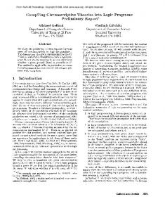
Figure 1: the Scheme of Object Manipulation paper, the point contact with friction model is used. That is, it assumes that there is only one contact point (In practical application of real robot hand, the geometry center of contact region servers as such contact point), and the friction between the fingertip and the object will be considered. In [12], the details of the contact model could be found. The meaning of the assumption of smooth surface have two aspects. one is that the normal vector to the surface of the object is unique. the other is to support the micro manipulation assumption. • Micro manipulation assumption In order to realize the median scale manipulation of the object, previous researchers mainly discussed the rolling and sliding control mode in robot control community. They expected to actively control the rolling and sliding the fingers on the object to realize the manipulation. Actually in the real world it is difficult to explicitly control the sliding and rolling manipulation if the unknown object’s geometry and friction knowledge are not available. So we propose to use the micro manipulation method. That means that we argue that median scale manipulation can be divided into many small pieces micro manipulation and such small piece micro manipulation can be realized based on the assumption that the velocity of contact point on the object and on the finger is the same if the surface of the object and the fingertip is continuous and differentiable. In this case, the rolling/sliding behavior of the fingers on the object which are not explicity controlled can be considered as the motion disturbance during the course of every micro manipulation. At every time instant, the robot hand will detect current contact information and the desired object trajectory to online plan the new micro manipulation. B. Kinematics Analysis of Manipulation Figure 1 shows that an multifingered hand is manipulating an object.In order to analyse the manipulation capability of robot hand, three coordinate frames should be defined. (1)the reference coordinate frame–Or ,this is an inertial reference frame.The origin of this frame can be defined at any point in the space. (2)the object coordinate frame–Oo ,this frame will move with the motion of the object.The origin of this frame is defined as any an reference point on the object. (3)the contact coordinate frames–Ocf , Oco ,these two frames will occur simultaneously when the fingertips contact the object.The origin of
3
the contact frame Ocf is defined as the contact point on the fingertip and the origin of Oco is defined as the contact point on the object.They have the same coordinate value in the reference coordinate frame, but they are located at the different objects. In Figure 1, for the purpose of clear visualization, only the contact coordinate frame on the index finger and the contact coordinate frame on the object (contacted with the middle finger) are shown. According to the kinematic model provided by [9], the relation between the velocity of the contact point on the object and the contact point on the finger can be obtained: ~vcf i
~˙ f i = ~v oi + Ro · S ~˙ oi + Rf i · S c
(1)
~oi ~vcoi = ~vo + ω ~ o × Ro · S
(2)
~vo is the linear velocity of the reference point on the object and ω ~ o is the angular velocity of the object.~vcf i ,~vcoi means linear velocity of the contact point on the ith fingertip and on the object, Rf i means the transform matrix of the distal phalange (last link of finger) coordinate frame relative to the reference ~f i describes the surface of the distal phalange coordinate frame.S ~oi can be defined in the similar method. of the ith finger. Ro and S Thanks to the micro manipulation assumption, we can calculate the desired linear velocity of the contact point on the fingertip given the desired position and orientation of the object. The angular velocity of the object can be calculated following the method proposed by [11]. C. Inverse Kinematics of multifingered Hand By the description of II-B, it’s clear that the desired trajectory of fingertips contact points can be obtained given the desired trajectory of the object. In order to track the desired trajectory of contact point by changing the joint angle, we use the inverse kinematics of robot hand. Inverse kinematics model of robot hand describes one mapping from the Cartesian space to the joints angle space. The formula can be described as: ˙ θ~ = JF−1 (~x˙ )
(3)
where x˙ is the linear velocity of the contact point, θ˙ is the joints angle velocity and the mapping JF is the Jacobian matrix from the joint angle space to the Cartesian space at the current joint angle configuration. If the dimension of ~x – m is equal to ~ the dimension of θ–n,−1 means the standard inverse mapping. If n > m ,−1 means the pseudo-inverse mapping. With the inverse kinematics the desired velocity of joint angle will be obtained given the desired velocity of contact point. III. H IERARCHICAL C ONTROL S TRUCTURE According to description in II, it’s an intuitive idea to realize such manipulation with a hierarchical control implementation. In the highest level, the desired trajectory of the object is designed according to the task on hand. Usually the interpolation method needs be used in order to make
Figure 2: Object Manipulation Hierarchical Control Flow Chart
the consecutive trajectory points distance be small enough to acquire the smooth object manipulation. This trajectory can be described in the manifold space of the SE(3) space, eg.(xod , yod , zod , φod , θod , ψod ), which represents the desired position and Euler angle of the object. Then according to the II-B, in the middle level, a finger motion and contact force solver is implemented to obtain the desired velocity of contact point~vcf i = (x˙ fc i , y˙ cf i , z˙cf i ) and desired contact force (scalar value in normal vector– → − n = (nx , ny , nz ))(fid ) for every finger. A simple online force planner is used P to keep the resultant force in normal vector to be zero– f~id = 0, because it’s a local manipulation. The vector symbol means that the direction of contact force – fid is considered. This force planner becomes not feasible longer in the global manipulation because the contact normal vectors of different finger become not collinear any longer in that case. In the lowest level, it is a position/force servo closed loop control circuit which can guarantee that the contact points on the fingers can track the desired velocity from the fingers motion solver and the fingers can contact the object with the desired force in contact normal vector. The desired velocity and contact force error will be superimposed after they are regulated by the corresponding traditional PI controller. It can be described: ˆ ~em = g1 (~vcf i ,
~vcf i )
(4)
~ i = (fid − fif b ) · ~n δf
(5)
ˆ ~ef i
= g2 (~δfi ,
~δfi )
~e = ~em + ~ef i
(6)
(7)
where fif b is the ith finger contact force feedback in normal vector.~e will be considered as the hybrid force/position tracking error and sent to the inverse kinematics module. the two mapping g1 ,g2 are the controllers.The whole control structure is shown in Figure 2.
4
the Object Position
6.8
(cm)
6.7 6.6
Z
6.5 6.4 6.3 6.2 2.6
1.6 2.4
1.4 1.2
2.2 Y
(cm)
2
Figure 4: Modeling Tactile Sensor
1 X
(cm)
(a) Object Transverse Along X Axis
(b) Object Rotate Around X Axis
Figure 3: Examples of Object Manipulation
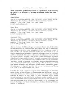
IV. S IMULATION E XPERIMENT A. Simulation Environment and Results The simulation experiment is run in simulation toolkit– NEO, developed by Neural Informatics group in Bielefeld University[1]. Physics engine–vortex is used as the backend, which can provide the accurate contact information (position,force) and the object information (position,orientation)feedback. Inverse kinematics functions of KDL (Kinematics and Dynamics Library)[2] is also used as the inverse kinematics module. With this module, the joint rate can be calculated once the contact point velocity servered as input. It is feasible to transfer this algorithm to the real world. By robot vision the pose of the object can be extracted if marker is attached on the object[?],[?], and contact position and normal vector can also be extracted by the tactile sensor on shadow hand, its geometry modeland the known kinematics model of shadow hand. The tactile sensor of shadow hand’s fingertip model is visualized as Fig.4. Outside green layer is the form of fingertip and inside cell set are tactile sensors. The normal vector of every tactile sensor is known. As an evaluation to the local manipulation strategy, the appropriate volume cylinder and slender cube objects are selected and manipulated in 6 D.O.F. by the robot hand (no geometry model of the cylinder is known to the robot hand in prior). The reason why selecting such objects is that it can avoid
the complex and global position and force planning caused by complex object geometry and let us focus on the local manipulation with our proposed control strategy. Before the realization of local manipulation, there is another important issue–”grasp” needed to implement. There is much research work on robot hand grasp. It is not our focus in this paper, so we just use a simple setting points grasp strategy to grasp the object for the convenience. The implementation of grasp is described as follow. • Assuming the virtual contact points on the fingertips and approaching the virtual contact points to the desired contact points on the object. • Tactile sensors detect the contact between the object and the fingertips, and the contact points on the fingertips will be recorded and serve as the new actual contact points. Then new contact points approach the desired contact points on the object. • The desired contact force is exerted on the object in the contact normal vector direction. In the whole grasp process, the frozen object is assumed. That means that the asynchronous contact of different fingers will not knock down the object. After the stable grasp–the predefined desired contact points and the desired force are approaching, the object is unfrozen. Then the manipulation task is executed. In principle, the object can be manipulated along an arbitrary trajectory defined at 6 D.O.F only if the consecutive trajectory point is small enough in the limited hand workspace. But as a evaluation simulation we just define the task as moving along and rotate around X,Y,Z axis of the reference coordinate frame. Because of the limitation of paper pages, only the cylinder object manipulation result:to move along X axis and to rotate around X axis is shown in figure 3. In 3a, the small scale reciprocating motion is shown along X axis since the limitation of workspace of the robot hand. The length of moving is 0.5cm.In 3b, rotation motion around X axis is shown. This figure also shows the whole manipulation process (including grasp). At stage 0, the grasp is realized, and predefined desired force–1N is approached. At stage 1, the object is unfrozen. In this stage, the desired action of the robot hand is to keep the position and orientation of the object is unchanged. Because the unbalanced forces (every finger has the predefined contact force–1N) are exerted on the object and it serves as an instant disturbance to the balance of the object. The local reactive manipulation strategy will keep the object stability at
Linear velocity of contact point on thumb after regulated by the controllers 0.02
0
linear velocityY
−0.02 2000
linear velocityZ
its original pose by changing the desired contact force on the thumb and the position of contact point on the object. At stage 2, the object is manipulated and changed its’ Euler angle α from 0 to -0.2 rad, then back to 0 again. The simulation experiment shows that the object can be locally manipulated in the hand well and it also shows that the micro manipulation approach is feasible.
linear velocityX (cm/s)
5
B. Discussion Although in the reactive control strategy there are the rolling and sliding phenomenon of the robot hand. But it is realized in the different method with the traditional active control method in principle. In the traditional method, the friction cone (see the green cone in 1) and force closure are the key issue under the condition of the point contact with friction model. q (8) f12 + f22 ≤ µf3 Gf~c = −F~e
(9)
where f~c = (f1 , f2 , f3 ) is the contact force vector defined in the contact coordinate frame. G is the grasp matrix[12]. F~e is the arbitrary external wrench. Usually active rolling control requires that the desired contact force trajectory is constrained by Eq.8 and Eq. 9 and active sliding control requires that decreasing the contact normal vector force component to the critical value, then moving fingertip on the object under the constraint condition Eq.9. Apparently, the better knowledge to the friction force between the fingertip and the object is needed to realize the active sliding control. The better knowledge of the geometry of the fingertip and the object is needed to realize the active rolling control. In this reactive control strategy, it is not necessary. We would not like to endow the robot hand a global complex position/force trajectory planing model because it’s very difficult for such trajectory planning capability to reply to the unpredicted events which can not be considered during the course of programing. We prefer to a kind of exploration strategy from the local manipulation to the global manipulation. In the current local manipulation IV-A, the reactive control strategy realizes the rolling and sliding without the explicit knowledge about the friction cone because it replaces the complex unification force trajectory plan constrained by Eq.8,9 with the simplified force plan, that is, the contact force is collinear and the resultant force is zero. In the simulation experiment, the controllers are developed on the kinematics level and dynamics issue is realized in the physics engine. The controller parameters are set manually. The controllers will calculate the linear velocity of current contact points on the fingertips by superimposing the error components from the position and the force. Because the PI controllers are the lowpass filters, they also smooth the tracking trajectory. (see Eq.4 to Eq.7 ). In manipulation, the position error component will make the most contribution to the contact points movement along the tangent surface of the contact frame. The movement along the normal vector is the resultant result of two components. This
3000
4000
5000
6000
7000
8000
9000
10000
3000
4000
5000
6000
7000
8000
9000
10000
3000
4000
5000
6000 Sampling step.
7000
8000
9000
10000
0.1
0
−0.1 2000 0.1
0
−0.1 2000
Figure 5: Contribution to the Velocity of Contact Point (Thumb)
result is visualized in Fig.5. The data showed the stage 1 and 2 when the fingers are moving the object along X axis. The blue dash-dot line represents the contribution of force error component. The green dash line represents the contribution of the desired velocity of contact points from the fingers motion solver. The red solid line represents the superimposition of the two contributions. The relation of the coordinate frame is shown in Fig 1. The data is described in the reference coordinate frame. According to the configuration of robot hand and its manipulation, the normal vector is along the Y axis. Apparently, movement of contact point along the tangent surface (composed by X,Z axis) is decided by the desired contact point linear velocity from the fingers motion solver and the movement of contact point along the normal vector is decided by the two components. V. C ONCLUSION In this paper, we proposed a novel reactive strategy to solve a general object local manipulation with an multifingered robot hand. Firstly, we proposed that the manipulation is based on the point contact model and micro manipulation assumption. The simulation experiment showed the micro manipulation assumption method to be feasible. With this method the multifingered robot hand can manipulate the object successfully moving along the desired trajectory, even the geometry of the object is unknown and the interaction between the object and the fingers is unpredicted. VI. ACKNOWLEDGEMENT Qiang Li gratefully acknowledges the financial support from Honda Research Institute Europe for the project Autonomous Exploration of Manual Interaction Space. R EFERENCES [1] The graphical simulation toolkit Neo/NST. http://ni.www.techfak.unibielefeld.de/neo. [2] KDL wiki | the orocos project. http://www.orocos.org/kdl. [3] ShadowHand company. http://www.shadowrobot.com/hand/. [4] M. Huber. A Hybrid Architecture for Adaptive Robot Control. PhD thesis, University of Massachusetts - Amherst, January 2000.
6
[5] J.J.Xu and Z.X.Li. A kinematics model of finger gaits by multifingered hand as the hybrid automaton. Automation Science and Engineering, IEEE Transactions on, v5(no.3):467–479, July 2008. [6] J. Kerr and B. Roth. Analysis of multifingers hand. The International Journal of Robotics Research, v4(no.4):3–17, January 1986. [7] P. Michelman. Precision manipulation with a dexterous robot hand. 1993. [8] D. J. Montana. The kinematics of contact and grasp. The International Journal of Robotics Research, v7(no.17), 1988. [9] M.Zribi, J. Chen, and M.S.Mahmoud. Control of multifingered robot hands with rolling and sliding contacts. Journal of Intelligent and Robotic Systems, v24(no.2), February 1999. [10] E. Paljug, X.P.Yun, and R.V.Kuma. Control of rolling contacts in multi arm manipulation. Technical report, University of Pennsylvania, 1992. [11] R.Campa and H.Torre. Pose control of robot manipulators using different orientation representations: A comparative review. In Ameriacan Control Conference, pages 2009 June 10–12, St.Lois,MO,USA, 2009. [12] R.M.Murray, Z.X.Li, and S.S.Sastry. A Mathematical Introduction to Robotic Manipulation. CRC Press, 1994. [13] T.Schlegl and M.Buss. a Discrete-Continuous control architecture for the dexterous manipulation. volume v2, pages pp.860–865, 1999.