Programmable matter by folding E. Hawkesa, B. Anb, N. M. Benbernoub, H. Tanakaa, S. Kimc, E. D. Demaineb, D. Rusb, and R. J. Wooda,1 a School of Engineering and Applied Sciences, Harvard University, Cambridge, MA 02138; bComputer Science and Artificial Intelligence Laboratory, Massachusetts Institute of Technology, Cambridge, MA 02139; and cDepartment of Mechanical Engineering, Massachusetts Institute of Technology, Cambridge, MA 02139
Programmable matter is a material whose properties can be programmed to achieve specific shapes or stiffnesses upon command. This concept requires constituent elements to interact and rearrange intelligently in order to meet the goal. This paper considers achieving programmable sheets that can form themselves in different shapes autonomously by folding. Past approaches to creating transforming machines have been limited by the small feature sizes, the large number of components, and the associated complexity of communication among the units. We seek to mitigate these difficulties through the unique concept of self-folding origami with universal crease patterns. This approach exploits a single sheet composed of interconnected triangular sections. The sheet is able to fold into a set of predetermined shapes using embedded actuation. To implement this self-folding origami concept, we have developed a scalable end-to-end planning and fabrication process. Given a set of desired objects, the system computes an optimized design for a single sheet and multiple controllers to achieve each of the desired objects. The material, called programmable matter by folding, is an example of a system capable of achieving multiple shapes for multiple functions. reconfigurable robotics ∣ self-assembly ∣ multifunctional materials ∣ computational origami
E
very day, scientists and engineers design new devices to solve a current problem. Each device has a unique function and thus has a unique form. The geometry of a cup is designed to hold liquid and is therefore different from that of a knife which is meant to cut. Even if both are made of the same material (e.g., metal, ceramic, or plastic), neither can perform both tasks. Is this redundancy in material, yet limitation in tasks entirely necessary? Is it possible to create a programmable material that can reshape for multiple tasks? Programmable matter is a material whose properties can be programmed to achieve specific shapes or stiffnesses upon command. In this paper we consider the theory and design of programmable matter material that can assume multiple desired shapes on demand. We have developed a unique concept of self-folding origami with universal crease patterns that decreases the complexity in individual elements and is scalable in the number and size of elements. Instead of relying on many individual subunits, which may be complex and difficult to orient correctly, we utilize a single sheet with repeated triangular tiles connected by flexible creases. This sheet can fold with a certain crease pattern to create multiple three-dimensional shapes, depending on which creases fold, in which direction, and in which order. We build on a large body of prior work in self-reconfiguring robotics to realize machines with changing shapes. Self-reconfiguring robots are modular systems whose bodies consist of multiple modules that can communicate and move relative to each other to form different shapes. These shapes support the different locomotive, manipulative, or sensing needs of the robot. Several different module designs and algorithms for coordinating the movement of these systems have been proposed. There are three classes of modular robots: chain (1), lattice (2), and hybrid (3–5). The modules move relative to each other using relative module motion (3, 5), module disconnection (6), or random motion (7, 8). The theoretical investigawww.pnas.org/cgi/doi/10.1073/pnas.0914069107
tions consider motion planning and design bounds (9–11), generic planners that can be instantiated to different robot bodies (12), and architecture-specific planners. An extensive review of the achievements and challenges in modular self-reconfiguring machines is given by ref. 13. Much of this prior work considers unit-modules on the order of 5 –10 cm in size, whereas our work involves 1 cm modules. The work in this paper departs from the principle of relative module motion. The self-folding sheets have underlying modularity provided by the crease pattern but the triangular modules do not change location relative to each other. The fixed sheet structure reduces complexity in design and planning and increases robustness by eliminating the need for continuously making and breaking connections to neighbors. Our work is related to recent work which has demonstrated the use of fluid forces to bend planar structures into well-defined three-dimensional structures (14). This system is analogous to our method of using actuation embedded within a surface to generate folds, however, without the ability to dynamically alter surface properties (e.g., dynamically controlled wetting properties), the user is restricted to a single shape programmed at design time. To realize self-folding sheets, we follow an end-to-end fabrication process from a set of desired shapes to a self-folding sheet that can realize each shape autonomously on demand. This process consists of two steps: the first step implements four planning algorithms in sequence. These algorithms determine a plan for folding certain creases such that all goal shapes can be created from a single sheet. Second, we fabricate a sheet according to this plan: for fabrication, we utilize recent developments in multimaterial manufacturing, embedded actuation, and stretchable electronics. In Process we describe the physical instantiation of the sheet, and in particular the thermally induced solid state phase transition (shape memory) actuators. By implementing this two-step process, we have demonstrated working programmable matter. In this report, we present the theory behind our origami concept, the planning and fabrication process, and finally the results of a fabricated sheet less than 0.5 mm thick that achieves two complex functional shapes, a boat and an airplane. Fig. 1 shows the current self-folding sheet, highlighting the key components. We also discuss the gaps between theory and practice, and point to a number of open questions toward more capable future programmable matter. Theoretical Background The theoretical basis of our self-folding programmable matter arises from the field of computational origami, an area of computer science that began in the 1990s (15, 16). One early result in this field (17) states that every polyhedral surface can be folded from a sufficiently large square of paper, and the folding can be computed in polynomial time. Thus a large enough sheet of Author contributions: E.D.D., D.R., and R.J.W. designed research; E.H., B.A., N.M.B., H.T., and S.K. performed research; and E.H., B.A., E.D.D., D.R., and R.J.W. wrote the paper. The authors declare no conflict of interest. This article is a PNAS Direct Submission. 1
To whom correspondence should be addressed. Email:
[email protected].
This article contains supporting information online at www.pnas.org/lookup/suppl/ doi:10.1073/pnas.0914069107/-/DCSupplemental.
PNAS Early Edition ∣
1 of 5
ENGINEERING
Edited by Gilbert Strang, Massachusetts Institute of Technology, Cambridge, MA, and approved June 2, 2010 (received for review December 7, 2009)
There are several issues that increase the gaps between theory and practice. First, the theory provides an algorithm to design a folding of any three-dimensional voxel shape, but can be inefficient in its required sheet resolution. In practice, we find that human origamists can often design more efficient foldings from a given-resolution sheet. Second, the theory assumes that the sheet has zero thickness, while real materials have positive thickness. Thickness is an issue mainly for compound folds, where one folds multiple layers of material at once, which we resolve by using stretchable material for crease joints. Third, the theory assumes that the sheet can flex during the motion to a folded state, while the material we use is relatively stiff to simplify control. Fourth, the theory also assumes continuous control—that the entire sheet can be completely controlled in an arbitrary fashion— while digital control necessitates discrete control with a finite number of actuators and uncertainty. Nonetheless, we show that reliable discrete controllers exist and can be computed for the practical shapes we consider. Process To create a self-folding smart sheet, we have developed a two-step process of planning and fabrication. The planning process begins with a set of goal configurations. After completion, it returns a plan of the optimized location and control sequence of creases that must be folded to create such configurations. The second step is the fabrication process which takes this specific plan and produces a working sheet. This process is depicted in Fig. 2.
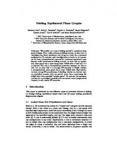
Fig. 1. 32-tile self-folding sheet, capable of achieving two distinct shapes: a “paper airplane” and a “boat.” Joule-heated SMA bending actuator “stapled” into the top (A) and bottom (B) sides of the sheet. Patterned traces cross the silicone flexures and are shown unstretched (C) and after stretching as a flexure bends 180° (D). Silicone flexure bent 180°, with both a single fold (E) and folded again to create a compound fold (four layers thick) (F).
programmable matter patterned with a specific crease pattern is capable of achieving any specific polyhedron. However, every desired shape might require a different crease pattern. To design programmable matter that can fold into multiple shapes, we require a new theory of universal crease patterns. We use a box-pleat pattern (Fig. 1), which has square subunits composed of eight isosceles triangles. Motivated by programmable matter, we recently proved that an n × n box-pleat tiling has as a folded state any polyhedral surface made up of OðnÞ unit cubes on the cubic lattice (18). Another theorem guarantees that any such folded state can be reached by a continuous folding motion without the material penetrating itself (19). This combined theory allows the creation of exponentially many foldings out of a single tiled crease pattern. By a standard voxelization procedure, any polyhedral surface or solid can be approximated on the cubic lattice. Therefore the box-pleat tile is a universal crease pattern that can fold into any polyhedral surface of a specified resolution. The practical aspects of this result and its implications are discussed more below. This theory suggests building a regular pattern of potential wells such that the potential energy reaches a local minimum as the crease becomes completely folded. If the face of each triangle in the box-pleat pattern is attracted to the face of each of its three neighbors, then it can be shown that any combination of folds will result in attraction and thus a local potential energy minimum. 2 of 5 ∣
www.pnas.org/cgi/doi/10.1073/pnas.0914069107
Planning Algorithms. The planning process consists of four distinct algorithms: the input to the process is one or more folded states of a common box-pleat grid, which can be computed by the universality algorithm of ref. 18 or designed by human origamists. The output is a design of a programmable matter sheet and controllers for folding that sheet into any of the input shapes. The first planning algorithm unfolds each of the given shapes. This algorithm is based on a rigid origami simulator (20) which is able to fold a shape given a set of creases. We apply the simulator in reverse to heuristically unfold a given three-dimensional folded state, by applying local unfolding forces at the creases. Upon success, the simulator returns a continuous path for each tile during unfolding. The second algorithm takes in the continuous folding paths from the first algorithm and produces a discrete folding plan. This plan includes which creases must fold, in which direction, and at what time in the folding process. The algorithm discretizes the given continuous motion into discrete time intervals called phases. Creases belonging to a common phase are all folded simultaneously. The first and second algorithms are run sequentially for each one of the goal shapes, producing an individual discrete plan for each goal shape. For example, if three goal shapes are desired, these algorithms will produce three plans for three separate sheets, each able to fold into one of the goal shapes.
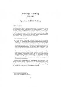
Fig. 2. The development of the programmable material first uses planning algorithms to plan a single shape, then merges multiple plans for multiple shapes, and finally outputs a design for how to fabricate the components of the sheet.
Hawkes et al.
Fabrication Process. The second step of our process is the fabrication of the three components of the programmable material: the tiled composite sheet, thin-foil actuators, and flexible electronics. The first component, the sheet, must have semirigid tiles to transmit force from the actuators, yet have joints stretchable enough to allow compound folding*. To create the sheet we laminate a single sheet of sixteen-layer E-glass fiber (104 weave), impregnated with RS-30 resin. Glass-reinforced composites are used for the tiles because of high strength, light weight, ease of machinability, and material compatibility with silicone-based elastomers used for the joints. The uncured composite sheet is laser micromachined with a CO2 laser (from Universal Laser Systems) to create slots for magnets. The magnets are used to create the potential wells discussed previously in Theoretical Background. The composite is cured at 140° C for four hours then micromachined to form the tile pattern. Alignment is ensured by machining the tiles while attached to a tacky substrate (Gel-Pak X8). Flexures are created by casting two-part GI-1100 RTV-2 silicone rubber (Fig. 1E). Elastomeric joints are essential for complex shapes since the joints need to stretch as well as bend. The resulting sheet can then be released and further machined for actuator attachment, metal deposition, or other additive or subtractive processes. This composite process shares similarities with Shape Deposition Manufacturing (22) and Smart Composite Microstructures (23), both *A compound fold is a fold that creases two or more layers of the sheet at once. These multiple layers are created through previous folds, see Fig. 1F.
Hawkes et al.
of which were established as rapid fabrication techniques for composite robotic structures. Actuators for the sheet must be low profile, simple to attach to the sheet substrate, and easy to create in quantities of tens or hundreds (depending upon the sheet dimensions and resolution). To put the actuator requirements in perspective, relatively large torques are necessary (on the order of tens of millinewtonmeters) to account for the mass of adjacent tiles, but the thickness cannot exceed that of the sheet (approximately 500 μm) so as to avoid interference during operation. High torques can be achieve geometrically (i.e., using a larger moment arm), however this is not a viable option for the sheets. Our unique thin-foil actuators, the second physical component, are capable of 180° of folding motion and are easily embedded within the tiling. We use thin (100 μm) foil Nitinol shape memory alloy (SMA) for the actuator material. The planform geometry is formed with a pulsed ultraviolet laser micromachining system. The micromachined foil is tinned, fixed in a jig to hold a desired (folded) shape, and annealed at 420° C for 30 min. This annealing process resets the undeformed martensitic state such that when unfolded, the actuator will “remember” its folded shape when heated above its transition temperature of 70° C (24). Thus any fold that is annealed into SMA can be manually flattened, and upon actuation, the fold is reformed. There are four folds in each actuator: one central bending fold, and three distal clamping folds. For assembly onto the sheet, we open all four folds (Fig. 3, top). The actuator is placed onto the sheet with each of the three legs inserting into a through-hole. The distal bends are heated with an external source, causing them to close (Fig. 3, middle). This results in a heat-activated staple, which tightly grips the substrate (Fig. 1 A, B). When the central fold is heated, the actuator folds tightly closed, which is the source of folding actuation for the sheet (Fig. 3, bottom). These actuators only remember folds in one direction (i.e., they fold from 0–180°). We have also prototyped antagonistic (bidirectional) actuators, however, for the algorithms and shapes discussed in this paper, only unidirectional actuators are needed. Thus, to minimize undesired complexity and maximize fabrication efficiency, only unidirectional actuation is described. The third component of programmable matter is the stretchable electronics, which are capable of bridging the elastomer flexure creases. It is essential that the electrical traces can not only bend while the tiles are folding, but also stretch to achieve compound folds. This presents a significant challenge which is not achievable with standard flexible circuits. As a solution, we pattern the trace with a series of cuts, or a mesh, that allows the metal to lengthen as needed (Fig. 1C). The meshes are micromachined from a sheet of copper-laminated polyimide in the exact pattern needed and bonded to the surface of the tiling. The actuators are soldered to the traces forming groups of actuators, as determined by the planning algorithm, to form a single power circuit. Thus to fold a shape, current is applied through one or more groups, heating all actuators in this phase through Joule heating until folds are complete and magnets engage. Then a second set of groups, or phase, is activated, a third, etc. Programming. An important aspect of creating programmable matter is the actual programming that allows a user to trigger the formation of the desired shape. For the self-folding sheet, we developed a method for programming shapes by stickers. The idea is to enable users to request the formation of a shape without the use of a computer. The intuition is to create the smart sheets to include all the electronic circuitry except for actuator and connector wiring. Stickers are thin materials that contain the circuitry required to connect and trigger the correct actuators for making a specific object. If we have k objects that are achievable from a base sheet, the user will receive the base sheet and k stickers, each of which programs the formation of one of the k PNAS Early Edition ∣
3 of 5
ENGINEERING
The third algorithm receives each of the individual plans from the second algorithm and assembles them onto one sheet. Then the algorithm takes all creases that need to be folded from all the incoming plans and divides them into groups. These groups are created such that every phase from the incoming plans can be written as a linear combination of the new groups. That is, activating one or more of the groups created by the third algorithm can create the first, second, third, etc. phase from the plan for the first shape, as well as the first, second, third, etc. phase for the second goal shape, and so on. This algorithm is run once for each possible arrangement of individual plans from the second algorithm on a single sheet. For example, if there are two goal shapes and the second algorithm returns two corresponding plans, then these two plans can fit simultaneously on a single square sheet in eight different arrangements (four 90° rotations and one 180° flip). Finally, the fourth algorithm chooses the optimum arrangement from the output of the third algorithm to minimize either the number of actuators or number of actuator groups. We either minimize the number of actuators to save energy and fabrication time, or minimize the number of groups of actuators to eliminate unnecessary circuitry and minimize folding time by maximizing parallelism. Finally, we check for detrimental antagonistic overlaps which can cause incorrect folding. An antagonistic overlap requires a crease to bend one way for one shape and the opposite way for a second shape. Bidirectional actuation is possible in practice but brings added mechanical complexity, which we avoid with the simple unidirectional actuators described as part of the fabrication process. Therefore, we remove the actuator from such a crease to allow passive motion caused by the folding of other creases. Often we find that the folding of other creases correctly folds the passive crease, both in simulation and in practice; otherwise, we call the passive crease detrimental. Any arrangement with a detrimental antagonistic overlap is discarded. The running time of the last three algorithms is polynomial for a fixed number of target shapes. For a large number of shapes, we would have to replace the exhaustive search over all arrangements of individual plans on a sheet. The running time of the first algorithm has not been analyzed, but its similarity to the gradient flow of ref. 21 suggests that a pseudopolynomial time bound holds.
sheet, with twenty actuators, five actuator groupings (Groups 1–5), three phases (Phase A–C), and two goal shapes (“boat” and “airplane”). This design is optimized to use the minimum number of actuators, 14.4% fewer than nonoptimized arrangements. Upon activating Groups 1, 2, and 3 the nine actuators of Phase A are heated, and the “boat” folds (Fig. 4 A–D). Once unfolded by hand, Groups 2 and 4 are activated, and Phase B (the triangular flaps) of a “paper airplane” folds (Fig. 5 A–C). Finally, Groups 3 and 5 receive current, and Phase C, the second phase of the “airplane” (backbone and wings), folds (Fig. 5 D–F) (See also Movie S1). One amp is run through the actuators, each with a resistance of 0.25 Ω, resulting in 1–2.25 W of power depending on the phase. Each phase takes between 6 and 10 s to fold, requiring between 6 and 22.5 Joules of energy for activation. Speed can be increased, but at the expense of a higher power input.
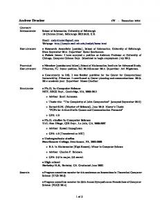
Fig. 3. SMA actuator unfolded after annealing (top). The actuator is “stapled” to the sheet in this position, with each of the three legs fitted through a hole in the sheet. Heat is applied at each red arrow to fold the three distal joints (middle). This causes the “heat-activated staple” to clamp the bottom side of the sheet. When the entire actuator is Joule heated, the central joint bends, folding the sheet 180° (bottom).
objects. Thus, programming the object reduces to placing the stickers on top of the sheet. Sticker Programming has three components: Programmable Matter with Sticker Operating System, Sticker Compiler, and Programmed Sticker device. Algorithms with the same flavor as the ones described for designing the placement of the actuators and the control for creating an object are used to automatically design the base sheet and the stickers that go with it. Results Using the two-step planning and fabrication process described above, we have designed, fabricated, and tested a thirty-two-tile
Discussion and Conclusion With the concept of self-folding origami, we hope to bring programmable matter into reality in the near future. We have presented an end-to-end approach to creating self-folding sheets capable of realizing multiple shapes. In theory, our algorithms can plan the creation of any three-dimensional shape. In practice, we are limited by actuator size and torque considerations, as well as control and coordination constraints for multiple actuators. At the moment, the self-folding devices we have created are limited to a finite set of shapes that can be created with oneway actuators. This limitation is primarily due to the physical realization of the sheet (one-way actuators, fixed wiring scheme, etc.), which is specified by the algorithm given the desired shapes. This limitation could be alleviated in one of two ways: (i) bidirectional actuation at each joint, each individually addressable by the controller or (ii) calculation of a large number of mutually compatible basis shapes from which goal shapes could be composed. The former would involve only the first two steps of the algorithm (the third and fourth are required to place multiple goal shapes in a predetermined manner on a single sheet). The latter is a natural extension of our current methods but with larger sheets with more actuation. The result would be a single sheet that can be folded into any shape up to a prescribed resolution. One important consideration for the practicality of this method is the scalability of the self-folding sheet, both in terms of resolution of the individual elements (tiles) and the number of elements that can be effectively combined in a single sheet. First, the resolution of the tiles is limited by the scalability of each element. The current materials and methods use to create the substrate can be reasonably shrunk to create tiles on the order of a few millimeters in largest dimension. Below this threshold, lithography and micromolding techniques (for example, molding elastomers using capillary action (25)) could be used to reduce feature sizes further. Scaling of actuation has two considerations:
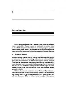
Fig. 4. Simulation (left) and experiments (right, with time shown in lower right—mm:ss.s) of a self-folding “boat.”(A). All actuators receiving current (B). Immediately before magnetic closures engage (C). Finished boat on side (D). 4 of 5 ∣
www.pnas.org/cgi/doi/10.1073/pnas.0914069107
Hawkes et al.
fabrication and performance. For fabrication, similar actuators could be reduced to millimeter feature sizes (26) using current methods or submillimeter scales using physical vapor deposition and patterning (27). For these actuator types, Joule heating becomes more effective at smaller scales, bandwidth will increase (mechanically as well as thermodynamically), and the energy density should remain constant. However, there are other potential actuation modes for smaller scales including pneumatic, electrostatic, and a variety of electroactive polymers (ionic and dielectric). We have shown that the gaps between theory and practice can be surmounted for the shapes we have considered. Nonetheless the gaps suggest additional theory that would be interesting to develop if possible. For example, can we quantify the flexibility of the material needed by motions of an unfolded sheet into target folded states? The area of rigid origami, which forbids flexing except at creases, is relatively underdeveloped, making this a challenging question. For a given resolution, we could also study whether it is always possible to reach a folded state without
unfolding any folds, which would provide theoretical backing for potential wells. Nevertheless, the current results suggest very promising applications. We can create a bulk material that is preprogrammed to adopt several shapes. Reconfigurable devices are an immediate application. Examples include a measuring cup system that folds to hold any amount from a quarter teaspoon to multiple cups, a shelving system that folds to fit a user-defined space with a userdefined number and type of divisions, and a puckering sheet that provides tactile feedback for displaying information to the blind or people in the dark. A wider range of devices could be incorporated to make a “Swiss army knife” of sorts, able to form a tripod, wrench, antenna, or splint. In the future, finer resolution and larger sheet sizes will become available as our manufacturing techniques evolve.
1. Yim M, Duff DG, Roufas KD (2002) Walk on the wild side. IEEE Robotics Automation Mag 9(2):49–53. 2. Rus D, Vona M (2001) Crystalline robots: self-reconfiguration with unit-compressible modules. Autonomous Robots 10:107–124. 3. Murata S, et al. (2000) Hardware design of modular robotic system. Proeedings of the Int Conference on Intelligent Robots and Systems 2210–2217. 4. Shen WM, et al. (2006) Multimode locomotion via SuperBot reconfigurable robots. Autonomous Robots 20:165–177. 5. Stoy K (2006) Towards robotic self-reassembly after explosion. Robotics and Autonomous Systems 54:145–151. 6. Gilpin K, Kotay K, Rus D, Vasilescu I (2008) Miche: modular shape formation by selfdisassembly. International Journal of Robotics Research 27:345–372. 7. Napp N, Burden S, Klavins E (2006) The statistical dynamics of programmed robotic self-assembly. Proc. of the IEEE Intl. Conf. on Robotics and Automation pp 1469–1476. 8. White P, Kopanski K, Lipson H (2004) Stochastic self-reconfigurable cellular robotics. Proceedings of the IEEE International Conference on Robotics and Automation 2888–2893. 9. Pamecha A, Ebert-Uphoff I, Chirikjian G (1997) Useful metrics for modular robot motion planning. IEEE Trans Robotics Automation 13:531–545. 10. Chiang CH, Chirikjian G (2001) Modular robot motion planning using similarity metrics. Autonomous Robots 10:91–106. 11. Chen IM, Burdick JW (1995) Determining task optimal modular robot assembly configurations. Proceedings of the IEEE International Conference on Robotics and Automation pp 132–137. 12. Butler Z, Kotay K, Rus D, Tomita K (2004) Generic decentralized control for latticebased self-reconfigurable robots. Int J Robotics Research 23:919–937. 13. Yim M, et al. (2007) Modular self-reconfiguring robot systems: opportunities and challenges. IEEE Robotics Automation Mag 14(1):43–52. 14. Guo X, et al. (2009) Two- and three-dimensional folding of thin film single-crystalline silicon for photovoltaic power applications. Proc Nat Acad Sci USA 106:20149–20154.
15. Demaine E, Demaine M (2001) Recent results in computational origami. Proceedings of the 3rd International Meeting on Origami Science, Math, and Education (A.K. Peters, Monterey, CA), pp 3–16. 16. Demaine E, O’Rourke J (2007) Geometric folding algorithms: linkages, origami, polyhedra (Cambridge University Press, New York). 17. Demaine E, Demaine M, Mitchell J (2000) Folding flat silhouettes and wrapping polyhedral packages: new results in computational origami. Comp Geom-Theor Appl 16:3–21. 18. Benbernou N, Demaine E, Demaine M, Ovadya A (2009) A universal crease pattern for folding orthogonal shapes. http://arxiv.org/abs/0909.5388. 19. Demaine E, Devadoss S, Mitchell J, O’Rourke J (2004) Continuous foldability of polygonal paper. Proc. of 16th Canadian Conference on Computational Geometry (CCCG 2004) (Montreal, Quebec, Canada), pp 64–67. 20. Tachi T (2006) Simulation of rigid origami (A.K. Peters, Pasadena, CA), pp 175–187. 21. Cantarella J, Demaine E, Iben H, O’Brien J (2004) An energy-driven approach to linkage unfolding. Proc. of 20th Annual ACM Symposium on Computational Geometry (SoCG 2004) (Brooklyn, New York), pp 134–143. 22. Bailey S, Cham J, Cutkosky M, Full R (1999) Biomimetic robotic mechanisms via shape deposition manufacturing. Proc. of the Int. Symp. on Robotics Research (Snowbird, Utah), pp 321–327. 23. Wood R, Avadhanula S, Sahai R, Steltz E, Fearing R (2008) Microrobot design using fiber reinforced composites. J Mech Design 130(5):52304–52314. 24. Kim S, et al. (2009) Micro artificial muscle fiber using niti spring for soft robotics. Proc. of the IEEE Int. Conf. on Intelligent Robots and Systems. 25. Kim E, Xia Y, Whitesides G (1995) Polymer microstructures formed by moulding in capillaries. Nature 376:581–584. 26. Leester-Schädel M, Hoxhold B, Lesche C, Demming S, Büttgenbach S (2008) Micro actuators on the basis of thin SMA foils. Microsyst Technol 14:697–704. 27. Wang X, Bellouard Y, Vlassak J (2005) Laser annealing of amorphous NiTi shape memory allow thin films to locally induce shape memory properties. Acta Mater 53:4955–4961.
Hawkes et al.
ACKNOWLEDGMENTS. This work is supported by Defense Advanced Research Projects Agency (DARPA) Grant W911NF-08-1-0228 (Programmable Matter).
PNAS Early Edition ∣
5 of 5
ENGINEERING
Fig. 5. Flat sheet prior to folding (A). Four-actuator group controlling flaps activated (B). Magnets for the first fold engaged (C). Remaining actuators are activated (D). Final shape (E) and inverted (F).