Proceedings of the 1999 Particle Accelerator Conference, New York, 1999
Progress towards simulating heavy ion beams for Inertial Fusion Energy based on 1) A Darwin model field solver, and 2) A semi-Lagrangian Vlasov solver ∗ E. Sonnendr¨ucker, LBNL, Berkeley, CA & CNRS, Nancy, France † , A. Friedman and D.P. Grote, LLNL, Livermore, CA Abstract We introduce in this paper two numerical methods, a Darwin model field solver and a semi-Lagrangian Vlasov solver, which may be appealing for beam simulations and discuss their properties.
1 1.1
THE DARWIN MODEL FIELD SOLVER
∇ × B = µ0 J +
Introduction
1.3
The Darwin model
The Darwin approximation of Maxwell' s equations is introduced to remove what is often the stiffest time scale in electromagnetic simulations, namely the propagation time of light waves from zone to zone. This model eliminates electromagnetic waves, but keeps other important parts of the physics, in particular the low frequency phenomena. The electric field E is decomposed into two parts, a longitudinal part EL which is curl free and a transverse part ET which is divergence free: E = EL + ET ∗ This
Asymptotic derivation from Maxwell's equations
Let us assume that the time derivatives are small in Maxwell' s equation. To emphasize this we write the dimensionless Maxwell' s equation introducing the small parameter ε: ∂E +∇×B ∂t ∂B ε +∇×E ∂t ∇·E ∇·B
−ε
= J, = 0, = ρ, = 0.
We express the fields E and B such that E = E0 + εE1 + ε2 E2 + . . . B = B0 + εB1 + ε2 B2 + . . . Plugging them into Maxwell' s equations, we get by gathering the terms in the same power in ε: The first order terms: ∇ × B0 = J0 ,
∇ · B0 = 0,
∇ × E0 = 0,
∇ · E0 = ρ0 .
The second order terms: ∂E0 , ∂t ∂B0 ∇ × E1 = − , ∂t
∇ × B1 = J1 +
∇ · B1 = 0 ∇ · E1 = ρ1 . 0
work was supported by the Director, Office of Energy Research [Office of Fusion Energy Science], U.S. Department of Energy under contracts No. DE-AC03-76SF00098 and W-7405-ENG-48. † Email:
[email protected]
0-7803-5573-3/99/$10.00@1999 IEEE.
1 ∂EL , c2 ∂t
and keeping the other three Maxwell' s equations unchanged.
The Darwin Particle-In-Cell formulation was introduced by Nielson and Lewis in 1976 [1]. This model, as described in detail in the next section, eliminates only the propagating light waves from the system, while retaining other slower time scale electromagnetic effects arising from the particle current sources. It has proved to be a mixed blessing over the years. Many authors have used the technique to great advantage, but have noted the difficulties sometimes encountered in its implementation [1], [2]. These problems arise from modifications of the originally hyperbolic system of equations which make the resulting system elliptic. Thus boundary conditions must be carefully formulated in order to ensure the problem is well-posed. Some of the most violent numerical instabilities experienced in plasma computations are associated with naive implementations of the Darwin method. However, certain beam simulations, which involve much less dense plasma might be spared these instabilities, and this could make the Darwin model very appealing in such cases.
1.2
where ∇ × EL = 0 and ∇ · ET = 0. Furthermore, as ∇ × EL = 0 we can write EL = −∇φ. Darwin' s approximation consists in dropping the transverse part of the displacement current from Ampere' s law:
Notice that ∇ ×E0 = 0 such that ∂E ∂t which appears in the second order terms only involves only the longitudinal displacement current. Therefore the following system yields the same terms in the expansions:
2758
Proceedings of the 1999 Particle Accelerator Conference, New York, 1999
– An equation for the scalar potential φ where EL = −∇φ −∇2 φ = ρ, – A system for the magnetic field B ∇×∇×B ∇·B
= ∇ × J, = 0.
• A second order approximate model ( E1 and B1 are also identical to those in Maxwell' s equations), is obtained if we include the transverse electric field ∇ × ∇ × ET
= −
∇ · ET
= 0.
The time differencing instability
In Nielson and Lewis [1] and Sonnendr¨ucker, Ambrosiano and Brandon [4], it is shown that there is a stability condition for the numerical time differencing of the source term for ET . This reads ωp 2 ≤ 1. c2 k 2 The smallest k seen by a mesh is π/L, where L is the length of the computational domain. Practically speaking, this means that if c/ωp ≥ L/π the simulation should be stable. Therefore the straightforward time-differencing can be used only for problems of length at most of the order of the collisionless skindepth. This condition is not fulfilled in most plasma problems where the Darwin model might be interesting (see [4] for a discussion). There is a remedy to this instability, but it involves gathering more moments from the particles and solving the following problem in dimensionless units Z ρET + ∇ × ∇ × ET = − v(v.∇x f) dv + ρEL Ω
∇ · ET
2.1
Introduction
Up to now space charge dominated beam simulations have been performed most of the time using Particle-In-Cell (PIC) methods such as those in WARP [5], which afford satisfying results with relatively few particles. However, it may be useful to have an alternative numerical approach in order to be able to separate more easily numerical and physical features in the simulation results. Therefore, we have adapted the semi-Lagrangian Vlasov method [6] to 2D slice beam simulations.
2.2
∂∇ × B , ∂t
This derivation has been performed in more detail and in a mathematically rigorous manner in [3]. Instead of Maxwell' s equations, which are hyperbolic, we now have three elliptic equations. Thus the Courant condition on stability no longer constrains the timestep.
1.4
SOLVER
The semi-Lagrangian scheme for 2D advection
The semi-Lagrangian method consists of looking for the value of the solution f at a set of mesh points by walking down the characteristics backward in time. The characteristics are the solutions of the differential system dX = vDx (x, y, t), dt
d They are such that dt f(X(t), Y (t), t) = 0, i.e. f is constant along the characteristics. The function f being known at the mesh points at the previous time steps, this property can be used to compute its new value. More precisely for a mesh point (xi , yj ), we have
f(xi , yj , tn + ∆t) = f(X(tn − ∆t; xi, yj , tn + ∆t), Y (tn − ∆t; xi, yj , tn + ∆t), tn − ∆t), where we denote by (X(t; x, y, s), Y (t; x, y, s)) the value at time t of the solution whose value is (x, y) at time s. Hence the algorithm can be decomposed in two steps: 1) Look for the starting point of the characteristic for each mesh point. 2) Compute f at the starting points of the characteristics. This interpolation is realised using a tensor product of cubic B-splines.
2.3
The electrostatic case
In the case where the Vlasov equation is coupled to a Poisson equation and submitted to a given external electric field, it can be split into two 2D advections, with a uniform advection field.
+J × B,
∂f + v · ∇x f = 0 ∂t
= 0
which is numerically costly as the right-hand-side of the first equation is not divergence free. However certain beam simulations which involve much lower ωp should be in the stable regime and hence make the Darwin model numerically a lot less costly. We are studying the possibilities.
dY = vDy (x, y, t). dt
and
∂f + E(x, t) · ∇v f = 0. ∂t
The “feet” of the characteristics are known explicitly. The displacement from the mesh points is the same everywhere, namely v∆t (or E∆t). The only numerical work in this case is to interpolate the distribution function at the previous time step using cubic splines. In the case of hard-edged quadrupoles a residence correction needs to be applied to get the correct force. This
2759
Proceedings of the 1999 Particle Accelerator Conference, New York, 1999 enters or leaves a quadrupole during a time step the applied field needs to be multiplied by the fraction of the time spent in the quadrupole. More precisely, if Eapp is the quadrupole field and ∆t1 is the time span spent in the quadrupole, then the applied field for this time step needs to be ∆t1 Eapp . ∆t
2.4
Parallelization methodology
Solving a four dimensional Vlasov equation is obviously very costly in time and memory. Therefore it requires massively parallel computing facilities. The most computationally intensive parts of the algorithm are the tridiagonal solves linked to the spline interpolation. These cannot be parallelized individualy with good scalability. For this reason we chose 1D band decompositions of the domain. We use a decomposition in bands parallel to the x-axis for the x-advection and a decomposition in bands parallel to vx -axis for the v-advection.
2.5
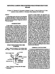
Figure 1: rms emittance from WARP calculation x-emittance (rms) (1284 grid)
Performance
We tabulate below the performance obtained on the NERSC T3E computer “mcurie” with 644 = 1.68 × 10⁷ grid points, 1 lattice period, and 30 time steps. PEs 4 8 16 32
time (s) 326.36 167.26 88.28 49.32
speed up 1 1.95 3.70 6.62
6.1 10-5 6.0
time/step/grid point (ns) 648.22 332.31 175.39 97.99
5.9
5.8
5.7
2.6
Propagation of a matched beam in a FODO channel
We compare the emittance evolution over 35 lattice periods of a matched beam. Figure 1 gives the WARP result and Figure 2 gives the SLV result for a 1284 grid. The results look quite comparable over this lapse of time. However, numerical dissipation is a serious problem in the semi-Lagrangian algorithm. In order for it to be kept small over a longer period of time the beam needs to be covered by a sufficient number of grid points. This implies the use of a very fine grid due to the beam oscillations in a FODO channel if a regular grid is to be used. More advanced methods, including adaptive grids, may prove useful in this regard.
5.6
0
5
10
15
20
25
30
Figure 2: rms emittance from SLV calculation [4] E. Sonnendrucker, J.J. Ambrosiano, S.T. Brandon, J. Comput. Phys. 121, 281 (1995). [5] D.P. Grote et al., this conference. [6] E. Sonnendrucker, J. Roche, P. Bertrand, A. Ghizzo, J. Comput. Phys. 149, 201 (1999).
3 REFERENCES [1] C.W. Nielson, H.R. Lewis, Methods in Computational Physics 16, 367 (1976). [2] D.W. Hewett and C.W. Nielson, J. Comput. Phys. 29, 219 (1978). [3] P.A. Raviart, E. Sonnendrucker, Numer. Math. 73, 329 (1996).
2760