12th IFToMM World Congress, Besançon (France), June18-21, 2007
The modified pitch cone method of the hypoid gear Jinliang Zhang1,2,*, 1. School of Science, Henan University of Science and Technology Luoyang, China 2. School of Mechatronic Engineering, Northwestern Polytechnic University, Xi’an, China ; Abstract—In order to improve the strength and endurance of hypoid gear, and extend the lifetime of hypoid gear, the modified pitch cone method is firstly introduced. On the condition of the invariant mean working tooth depth, invariant outer diameter of gear and the gear addendum coefficient
f a ≤ 0 , the new pitch cone parameters are derived. The new pitch cone is coincident to face cone or out of the gear solid. The tooth surface contact stress, the maximum tensile bending stress and maximum compressive bending stress are researched by using the finite element method. The computer simulation results show that the tooth surface contact stress, the maximum tensile bending stress and the maximum compressive bending stress of the pinion to hypoid gear pair designed by new method are markedly reduced. From the experiment, the new type hypoid gear pair can be processed by the general cutter, and the other special tool is unnecessary. Keywords: Hypoid gear pair; modified pitch cone; finite element method
I. Introduction Hypoid gear is widely used to transmit motion and power in automobiles and construction machines. Because of the complicated gear geometry, the design and manufacture methods of higher-strength hypoid gears have been paid attention by a number of researchers. Litvin et al. [1-3] proposed local synthesis of Formate and Helixform hypoid gears for conjugate gear tooth surfaces, and investigated the transmission errors and shift of bearing contact for hypoid gear drive. Based on grinding mechanism and machine-tool settings of the Gleason modified roll hypoid grinder, Lin et al. [4] presented a mathematical model for the tooth geometry of hypoid gear, and studied the correlation between the __________________________ *E-mail:
[email protected]
Zongde Fang, Xuemei Cao School of Mechatronic Engineering, Northwestern Polytechnic University, Xi’an, China
mathematical model and actual manufacturing machines. In Ref.[5], a mathematical model for the hypoid gear with modified roll motion was introduced. Shibata et al.[6] analyzed the relation between the tooth profile and the transmission error, and presented the method of decreasing the transmission error of hypoid gears. In order to reduce the transmission errors and improve the load distribution, Vilmos[7,8] introduced the method of optimal tooth modifications in the design of hypoid gears . In order to improve the strength and endurance, and extend the lifetime of cylindrical gear, the addendum modification method is often used in the design of cylindrical gear. Inspired by the addendum modification method of cylindrical gear, Liang[9,10] presented the nonzero modification design method for bevel gear. The nonzero modification technique [11,12] has successfully been applied in the design of the spiral bevel gear and the hypoid gear. In fact, the non-zero modification is the correction of angle. With the aid of separating the pitch cone from the reference cone in the design of the bevel gear, pressure angle on the pitch cone can be changed, and the tooth thickness of gear pair is changed correspondingly, too. Then the strength of the gear pair is improved. From the discussion above, it is easy to see that the bevel gear pair designed by the non-zero technique is only processed by the generating method. The application of the non-zero modification technique is greatly restricted, because a majority of hypoid gears used in automobiles are processed by Hypoid Formate Tilt (HFT, for short) method. In the traditional design of the hypoid gear [13], the numbers of pinion and gear, the shaft offset and the hand of spiral are determined according to the demanding of practical engineering. The outer pitch diameter of gear, gear face width and pinion mean spiral angle are
12th IFToMM World Congress, Besançon (France), June18-21, 2007
determined according as the demanding of the bearing capacity and strength of the hypoid gear pair. Then we can use the parameters mentioned above and radius of cutter to derive other blank data of hypoid gear. Because the gear outer pitch diameter of gear, gear face width and pinion mean spiral angle are key parameters to calculate the geometric parameters of hypoid gear, and much more influence on the bearing capacity and strength, in the second section, we use the modified pitch cone method in the hypoid gear design to modify the pitch parameters on the condition of the invariant mean working tooth depth and outer diameter of gear. The pitch parameters are modified, and the bearing capacity and strength of the hypoid gear designed by the modified pitch cone method are improved, similar to Liang’ non-zero modification design method.
R2′ =
r2′ , sin δ 2′
(3)
In the case of normal tooth taper, gear pitch angle after modification δ 2′ :
δ 2′ = δ a 2 −
57.3 f a h , R2′
(4)
In the case of duplex tooth taper, gear pitch angle after modification δ 2′ :
δ 2′ = δ a 2 −
176 ⎛ R2′ sin β 2′ ⎞ ⎟, ⎜1 − r0 z2 tan α ⎝ ⎠
If the hypoid gear pair is normal tooth taper,
formulae (1)-(4).
1 hae′ 2 = f a h + b2 tan(δ a 2 − δ 2′ ) , (1) 2 ′ 2 < 0 , it shows that new pitch When f a < 0 , then hae cone is out of the gear solid, thus the new pitch cone is named void pitch cone. Gear radius of pitch after modification r2′ and mean length of gear pitch cone generatrix after modification R2′ can be derived as
X2 1 − hae′ 2 cos δ 2′ − b2 sin δ 2′ , 2 2
δ 2′ , r2′ and
the other pitch cone parameters can be derived by the
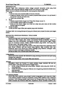
A hypoid gear pair has been designed by the Gleason method. On the condition of the invariant mean working depth and invariant outer diameter of gear, we set the gear addendum coefficient f a ≤ 0 , new pitch cone is coincident to face cone or out of the gear solid. The changing of gear blank after modification is shown in Fig. 1. In Fig. 1, PQ 1 1 = X 2 2 , X 2 is the outer diameter of gear, Points O2 , Oa 2 , O f 2 , H 2 are intersect point of gear shaft with pinion shaft, intersect point of gear face cone with gear shaft, intersect point of gear root cone with gear shaft, and intersect point of gear pitch cone with gear shaft before modification, respectively. Points H 2′ , P2′ are the intersect point of gear shaft with gear pitch cone, and the intersect point of gear shaft with the mean point of gear width on the pitch cone after modification, respectively. Gear outer addendum after modification can be calculated as follows:
r2′ =
δ 2′ , r2′ and
the other pitch cone parameters can be derived by the
If the hypoid gear pair is duplex tooth taper, II. The modified Pitch Cone Method
(5)
(2)
formulae (1)-(3), (5). Then the blank parameters of hypoid gear can be calculated P1
P3 P′2
X2 2
r′2
Q3 Q1
Q′2
O2
Oa 2
H2
H 2′ O f 2
Fig.1. Changing of gear blank after modification
III. Example for Hypoid Gear Drive Designed by the modified Pitch Cone Method An example of hypoid gear drive designed by the modified pitch cone method is considered in this section, and the maximum tensile bending stress and the maximum compressive bending stress are studied by using the finite element method.[16-18] A. The comparison of hypoid blank datum The table 1 shows basic blank datum researched in this section.
12th IFToMM World Congress, Besançon (France), June18-21, 2007
Number of teeth Face width/ mm Shaft offset/ mm Gear outer pitch diameter / mm Pressure angle/(o) Shaft angle/(o) Mean spiral angle/(o) Hand of spiral
Pinion 7
Gear 39 63
35 434.09 22.5 90 47 LF
RH
TABLE 1. Basic Blank Data
The duplex tooth taper is only considered in this paper, and we set f a = −0.12 . The comparison of hypoid blank datum derived respectively by Gleason blank formulae and the modified pitch cone method based on the basic blank data (in Table 1) shows in Table 2. Modified pitch cone Gleason method method Gear Pinion Gear Pinion Outer cone 222.60 222.75 distance/mm Mean cone 191.25 distance /mm 191.02 Pitch angle/(o) 77.170 78.013 Face angle/(o) 77.609 15.513 77.609 15.506 Root angle/(o) 74.231 12186 74.240 12.188 Mean 1.798 -1.660 addendum /mm Mean 14.162 17.620 dedendum /mm TABLE 2. The comparison of blank data
It is easy to see that the gear pitch angle of the hypoid blank designed by the modified pitch cone method is greater than gear face angle. B. Computer Simulation and Stress Analysis In terms of tooth contact analysis, contact pattern and contact paths on the gear surface, the transmission error curve to the new type hypoid gear are shown in Figs. 2,3.
Fig. 3. The transmission error curve
On the condition of same single Load(10000N)(on the point of the mean face width and same distance to root cone), the comparisons of the tooth surface contact stress, the maximum tensile bending stress, the maximum compressive bending stress and outer diameter between the Gleason method and modified pitch cone method are shown in Table 3. Modified Gleason Proportion pitch method of stress cone changing method Pinion the maximum tensile 29.83 26.17 12.27% bending stress/N/mm2 Pinion the maximum 52.35 50.57 3.4% compressive bending stress /N/mm2 Gear the maximum 49.86 48.74 2.24% tensile bending stress/N/mm2 Gear the maximum compressive 74.54 73.44 1.47% bending stress /N/mm2 Tooth surface 1484.66 1431.18 3.60% contact stress /N/ mm2 Pinion outer diameter/mm 120.71 128.00 Gear outer 434.99 434.99 diameter/mm TABLE 3. Comparisons of the tooth surface contact stress, the maximum tensile bending stress, the maximum compressive bending
Fig. 2. Contact pattern and contact paths on the gear surface
stress and outer diameter
In table 3, the tooth surface contact stress, the maximum tensile bending stress, the maximum
12th IFToMM World Congress, Besançon (France), June18-21, 2007
compressive bending stress of the hypoid designed by modified pitch cone method are reductive relative to Gleason method, and pinion outer diameter designed by modified pitch cone method becomes longer. The modified Gleason method pitch cone method Gear Pinion Gear Pinion Addendum outer 6.73 10.68 6.76 8.38 chordal tooth thickness /mm Root outer 23.92 31.96 24.19 34.89 chordal tooth thickness /mm Addendum chordal tooth 5.41 7.52 5.55 4.69 thickness on the toe/mm Root chordal 20.69 16.34 23.87 tooth thickness on 16.09 the toe /mm TABLE 4 Comparison of the Chordal tooth thickness
Table 4 shows that root chordal tooth thickness of the pinion designed by modified pitch cone method becomes thicker. Ⅳ. Experiment The meshing mark is shown in .Fig. 10.
Fig. 4. Meshing mark
From the comparison the Fig.2 with Fig.4, it is easy to see that real cut meshing mark is consistent with the design meshing mark. By using the local synthesis method and the basic blank datum in Table 1, the pinions designed respectively by the modified pitch cone method and by Gleason method are processed by HFT method and shown in the Fig.2.
(a) The pinion designed
(b) The pinion designed
by the modified pitch cone method
by Gleason method
Fig.4. Pinion outer tooth profile
The Fig.4 shows that the root chordal tooth thickness of the pinion designed by the modified pitch cone method becomes thicker, and pinion outer diameter becomes longer, and verifies the modified pitch cone method. Ⅴ. Conclusions In this paper, the modified pitch cone method is firstly introduced. By using the local synthesis method, the finite element method, the tooth surface contact stress, the maximum tensile bending stress and the maximum compressive bending stress of the hypoid gear pair designed by new method are researched. From the computer calculation, simulation and experiment, some conclusions can be made as follows: ⑴ The root chordal tooth thickness of the pinion designed by the modified pitch cone method becomes thicker, and pinion outer diameter becomes longer. ⑵ The maximum tensile bending stress and the maximum compressive bending stress of the pinion to hypoid gear pair designed by new method can be markedly reduced. The computer simulation and experiment show that the strength of new type hypoid gear is improved. ⑶ The hypoid gear pair designed by new method can be processed by HFT method, and the other special tool is unnecessary. References [1] Litvin F.L.and Gutman Y. Methods of synthesis and analysis for hypoid gear-drives of ‘Formate’ and ‘Helixform’,Part 1, 2,and 3, ASME Journal of Mechanical Design, 103 (1) : 83–113, 1981. [2] Litvin F.L.and Gutman Y. A method of local synthesis of gears grounded on the connection between the principal and geodetic curvatures of surfaces, ASME J. of Mech. Design, 103: 114-125, 1981.
12th IFToMM World Congress, Besançon (France), June18-21, 2007
[3] Litvin F. L., Chen J., Sep T. M., and Wang J. Computerized Simulation of Transmission Errors and Shift of Bearing Contact for Face-Milled Hypoid Gear Drive, ASME Journal of Mechanical Design, 117: 262-268, 1995. [4] Lin C.Y., Tsay C. B., and Fong Z. H. Mathematical model of spiral bevel and hypoid gears manufactured by the modified roll method, Mechanism and Machine Theory, 32: 121-136, 1997. [5] Lin C. Y., Tsay C. B., and Fong Z. H. Computer-aided manufacturing of spiral bevel and hypoid gears by applying optimization techniques, Journal of Materials Processing Technology, 114: 22-35, 2001. [6] Shibata Y., Kondou N. , and Ito T. Optimum tooth profile design for hypoid gear, JSAE Review, 18: 283-287, 1997. [7] Vilmos S. Optimal machine tool setting for hypoid gears improving load distribution, ASME Journal of Mechanical Design. 123: 577582, 2001. [8] Vilmos S. Optimal tooth modifications in hypoid gears, ASME Journal of Mechanical Design, 127: 646-655, 2005. [9] Liang G. M. New system of spiral bevel gear---- Theory of modified reference cone angle, Gear, 2:19-34, 1981. [10] Liang G. M., Deng X. Z. and He Z Q. New type technique of nonzero modified spiral bevel Gear, China Mechanical. Engineering, 8(1): 97-101, 1997. [11] Wan X. L., Liang G. M. and Wei R. Z. New method on design of hypoid gears, Chinese J. Mechanical Engineering, 29(5): 8-11, 1993. [12] Wan X. L. Research and application of generalized non-zero hypoid gear, Doctor Thesis, 1992. [13] Zeng T. The design and manufacture of spiral bevel gear, Press of Harbin institute of technology, Harbin, 1989.