A special sharp is mounted on QT to detect this beacon and navigate towards it.
.... 88-92. 93-94. 94-95. 105-108 120-124. 128. Right IR. 88-91. 95. 98-100.
QT: A Robot Pet Final Report
Jawad Khan Intelligent Machine Design Lab EEL5666 Summer 1999
2
QT: Final Report
Table of Contents
QT: A ROBOT PET ....................................................................................... FINAL REPORT .......................................................................................................................... 1 ABSTRACT: .............................................................................................................................. 4 EXECUTIVE SUMMARY: ....................................................................................................... 5 1.
INTRODUCTION:............................................................................................................. 6 STRUCTURE AND SHAPE ............................................................................................................ 6 HOME:...................................................................................................................................... 7 SENSORS................................................................................................................................... 7 PROCESSOR............................................................................................................................... 7
2. INTEGRATED SYSTEM:................................................................................................... 10 MAKING QT CUTE .................................................................................................................. 10 3. MOBILE PLATFORM:....................................................................................................... 12 TAMIYA BULLDOZER KIT ....................................................................................................... 12 4. ACTUATION:...................................................................................................................... 14 Actuation in QT is based on two small motors in Tamiya twin motor gearbox...................... 14 TWIN MOTOR GEARBOX KIT - ................................................................................................. 14 MOTOR CURRENT TEST:.......................................................................................................... 14 5. SENSORS:............................................................................................................................ 16 40 KHZ IR SENSORS ............................................................................................................... 16 32 KHZ IR SENSORS ............................................................................................................... 17 THE CDS CELL ....................................................................................................................... 17 BUMP SENSORS ....................................................................................................................... 17 MICROPHONES: A DIFFERENTIAL E AR!.................................................................................... 17 CIRCUIT DIAGRAM FOR THE MICROPHONE AMPLIFIER:............................................................. 18 SHAPE OF THE EARS: ............................................................................................................... 18 EXPERIMENTAL SETUP AND RESULTS ....................................................................................... 19 OBTAINING THE RANGE OF VALUES OF THE MICROPHONES: ...................................................... 19 SAMPLING THE VALUES OF MICROPHONES ............................................................................... 22 SAMPLING ALGORITHM ........................................................................................................... 22 THE DIRECTION COEFFICIENT.................................................................................................. 23 ACCURACY OF RESULTS:......................................................................................................... 26 6. HOME:................................................................................................................................. 27 MODULATION CIRCUITRY: ...................................................................................................... 27 7. BEHAVIORS: ...................................................................................................................... 28 EXPLORE THE UNIVERSE ......................................................................................................... 28 FEAR: ..................................................................................................................................... 28 SLEEP:.................................................................................................................................... 29 DANCE: .................................................................................................................................. 30 8.
CONCLUSION AND FUTURE EXTENSIONS.............................................................. 31
9. REFERENCES: ................................................................................................................... 32 10. SOURCES FOR PARTS:................................................................................................... 32 3
QT: Final Report
APPENDIX A: SOURCE CODES........................................................................................... 33 APPENDIX B: TJPRO ASSEMBLY MANUAL .................................................................... 47
Abstract: QT is a robot pet which is capable of living in a room. A Motorola 68HC11 board provides the processing horse power of this robot. This robot has 5 different kinds of sensors, including three 40KHz IR detectors, one 32 KHz IR detector, two bump sensors, one CdS cell, and two microphones. Four behaviors are implemented in this robot which are: Explore the Universe, Fear, Sleepy and Dance. A special sensor was developed for this class using the two microphones and this is called the differential ear. Using the differential ear the robot can tell the direction of the sound and dances to music in its dance behavior. These behaviors make full use of the sensors found on QT. In addition to the robot a home was also built which contains an IR beacon modulated at 32 KHz for the robot to detect. The robot successfully finds and navigates towards its home when it is frightened or sleepy.
4
QT: Final Report
Executive Summary: The objective of this project was to build a small autonomous mobile robot which can mimic the characteristics of an indoor pet. Special attention, therefore, was given to the shape of the robot to make it friendly and give it a more pet like nature. Two eyes were built to make it more cute. A home was also built which contains an IR beacon modulated at 32 Khz. There are five different kinds of sensors on this robot, including three 40KHz IR detectors, one 32 KHz IR detector, two bump sensors, one CdS cell, and two microphones. Four behaviors are implemented in this robot which are: Explore the Universe, Fear, Sleepy and Dance. Three 40 KHz IRs are used in the Explore the Universe behavior which is an obstacle avoidance behavior. The CdS cell provides the information when to sleep. 32KHz IR is used to detect Home and navigate towards it. The two microphones constitute the special sensor made for this class called Differential Ear. This is used in the dance behavior in which the robot dances to the music depending upon the source and direction of the sound. Overall the project was a success and I am very satisfied with the results.
5
QT: Final Report
1. Introduction: The name of this robot is QT. This is because it is a pet robot and really cute in nature. It will live in my room and will be behave as a pet. The overall shape of the robot was also designed by keeping the “cute” nature of the robot in mind.
At the time of writing this report there were four basic behaviors of this robot. 1. Explore the Universe: For QT the universe is the room in which it is living. When the robot is in this mode it will wander about navigating in the room till it detects one of the following events: Loud Sound or Darkness. 2. Fear: QT fears loud sounds and this frightens it. Therefore QT tries to find it’s home and go there. The Home is a cylindrical object which has an Infra-red beacon on it emitting IR light modulated at 32.75 KHz. 3. Dance: After finding the home and coming back to it QT will dance to the music or any sound that it hears. The dance steps will be based on the direction of the sound. 4. Sleep: When QT detects that it is dark in the room it will again go to its home an sleep there till it becomes day again. This is done with the help of a CdS cell on QT. Structure and Shape QT has a Tank like base with treads on the two sides. The tank base is made from the Tamiya Bulldozer kit. The shape was designed to bestow on QT a friendly and pet like character.
6
QT: Final Report
Home: QT has a home which is cylindrical in shape and has mounted on it an Infra red beacon so that it is visible from where ever QT is wandering in its universe. This IR beacon is a set of five LEDs mounted in a semicircle and modulated at 32.78 KHz. A special sharp is mounted on QT to detect this beacon and navigate towards it. Sensors 3 Proximity IR sensors, Bump, Light (CdS) sensor, 1 Home Ssensor (IR) Differential Ear (2 microphones) Processor A 68HC11A1 on a MTJPRO11 board serves as the brain of the robot. QT is shown in the photographs on the next page.
Section 2 of this report is concerned with System Integration. Section 3 talks about the mobile platform followed by the actuation mechanism discussed in section 4. Section 5 is a comprehensive description of the sensor of QT including the differential ear developed as a special sensor for this class. Section 6 takes care of the issues involved for designing the home for QT. Section 7 talks about the behaviors and the algorithms for implementing those behaviors. Section 8 is the conclusion and future extensions for the project.
7
QT: Final Report
FIGURE 1.1: QT
FIGURE 1.2: QT GOING TOWARDS ITS HOME
8
QT: Final Report
FIGURE 1.3: BACK VIEW: VARIOUS SWITCHES AND PARTS
FIGURE 1.4: FRONT VIEW: VARIOUS SENSORS AND PARTS
FIGURE 1.5: SIDE VIEW: VARIOUS PARTS 9
QT: Final Report
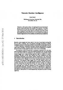
2. Integrated System: QT and its home represent a close relationship. QT knows that it is safe when it is at home and home is there for it. QT also goes to home when it is dark and it is time to sleep. QT gets the information from its sensors and then after processing issues commands to the motors and the mode LEDs. Complete system integration in QT is shown in Figure 2.1 below.
Bump Sensors
CdS cell Light Sensor
Home sensor (32KHz IR Sensor)
IR Proximity sensors
Ear Two Microphones
Processing
Mode LEDs
Motors
System Integration in QT
FIGURE 2.1 SYSTEM INTEGRATION IN QT
Making QT cute The job of making this robot really cute in nature was the most challenging one. I bought some colorful playing foam from ToysRus. This material is really light and is easily shaped. Also the wonderful colors in which it comes is exactly what I needed. I used Violet, Green, Yellow colors and made the body of QT. 10
QT: Final Report
The main body comprises of a purple circular cylinder, which will also serve as the hiding place for the relays of the motors. This purple circular cylinder will also house the IR transmitters and receivers. Two small yellow colored rectangular pieces in front and back of the Bulldoze kit serve as the housing for the bump switches. Also the bump switches are connected to two black, 6” long, IC containers which serve as the bumpers on this robot.
In order to bestow a personality to QT two eyes were added to the structure. The sockets are made out of a white toothpaste cover and a blue cover of a body spray! Two ping pong balls were inserted into these sockets and the sockets were connected to two springs so that the eyes would move in a funny way when the robot moves. This added character to the robot and makes it readily discernable as a cute thing.
11
QT: Final Report
3. Mobile Platform: The mobile platform of the robot is chosen to have a base like a Tank with treads on both sides. This decision was based on the fact that since the robot will have a “living” environment in a room, must have the ability to move on thick rugs and carpets; the usual flooring medium of rooms. Also the other consideration for designing the Platform was the ability to arouse emotion of love for the pet in humans. Therefore special attention was given to make it ‘cute’. For this reason the objective while designing the robot was not to make it bulky. The electronics and the actuation mechanics should be concealed from the eye. The robot should be small and the material used for giving the robot structure must be light and yet colorful. Tamiya Bulldozer Kit This kit was ordered from “The Robot Store” This is a pretty good kit with lots of extra parts and extra track segments. This kit features a Bulldozer base with twin motor assembly with a “wired” remote control. The reason for choosing this kit was primarily based on the fact that Tank Tread assemblies must be very accurate mechanically otherwise the treads come off with use. Therefore, to minimize the mechanical problems associated with a Tank tread base, I decided to buy this kit which comes complete with two motors and a gearbox for moving the treads.
However, when I assembled it and put the treads on, I realized that the tension in the treads was a little bit too much. I decided to add some extra segments to the 12
QT: Final Report
treads in order to lessen the tension. But the only choice available was a block of 8 segments, which could not move on the guides as the treads had now become too slacked. So I had to add two more guides at the top of the back wall of the main structure of the bulldozer, to accommodate the slack. But the problem with this arrangement was that I had no replacement shaft for the new pair of guides I wanted to add. A trip to Lowe’s provided me with a 1/8” thick rod which was the closest I could get to the required thickness. I used very small files to shape the guides, I was to put on the new rod. Also I made two support pieces out of the PC Board material and attached them to the back wall of the assembly. The new guides removed the slack and hence the problem of tension in the treads was solved.
13
QT: Final Report
4. Actuation: Actuation in QT is based on two small motors in Tamiya twin motor gearbox Twin Motor Gearbox Kit This kit features two DC motors & gears in a compact unit. Provides full fwd-revleft-right action. Two different gear ratios are available: fast 58:1 or strong 203: I built it with the default ratio suggested by the Bulldozer kit. Here are some of the specifications of this gearbox. Size: 75 x 50 x 23 mm. Shafts: 3 mm hex, 105 mm long. Figure 4.1 shows this gearbox.
FIGURE4.1: TWIN MOTOR GEAR BOX
Motor Current Test: A stall current test for the motors showed that they can draw a maximum current of 1.5A under stall conditions. Therefore the high current motor driver circuit using relays was used. This circuit is given in figure 4.2.
14
QT: Final Report
VCC
DPDT Relay
470 Ohm NPN 2N 2222
Direction from PD4
470 Ohm
NPN High Power Darlington
PWM from PA6
Motor Driver Circuit for Right Motor
VCC
DPDT Relay
470 Ohm
NPN 2N 2222
Direction from PD5
470Ohm PWM from PA3
NPN High Power Darlington
Motor Driver Circuit for Left Motor
FIGURE 4.2: MOTOR DRIVER CIRCUITRY FOR THE TWO MOTORS
15
QT: Final Report
5. Sensors: QT has following sensors in its sensor suite. 1. 40 KHz IR sensors (3) 2. 32KHz IR sensor (1) 3. CDS cell (1) 4. Bumpsensors (2) 5. Microphones (2) 40 KHz IR sensors These sensors are embedded in the cylindrical body of QT and these provide QT with the basic collision detection mechanism. All of these sensors are forward looking however two of these sensors are mounted at angle so that QT can have lateral view of obstacles as well. These sensors use IR light modulated at 40KHz. The IR LEDs are mounted inside heat shrink tubing to collimate the IR light and minimize back scattering. Some typical values of the analog port are given in the table below. Unblocked
12 inches
8 Inches
6 Inches
3 Inches
1 Inche
Left IR
88-92
93-94
94-95
105-108
120-124
128
Right IR
88-91
95
98-100
117-118
123-125
128-129
Center IR
85-86
95-96
100-105
115-116
120-123
127
FIGURE 5.1: TYPICAL VALUES FOR THE IR SENSORS WITH OBSTACLE AT VARIOUS DISTANCES
16
QT: Final Report
32 KHz IR sensors There is only one sensor of this type on QT. This is used to detect home beacon. Otherwise the home beacon could have blinded the collision avoidance Sharps. The CdS Cell This is a photo resistor and will be used to distinguish between night and day. QT must sleep at night so that everybody else can sleep too. The nominal value when unobstructed is 99. However when completely blocked the values range from 242244. Therefore a threshold of 200 was chosen to distinguish between dark places and not dark places. Bump Sensors One front and one back Bump sensors provide QT with the ability to back off if it collides with something. Microphones: A Differential Ear! Two microphones were interfaced to QT. These microphones provide the basis of QT’s listening abilities. This sensor has enabled QT to distinguish the source of a sound and then navigate towards it. This is also to be considered as a special sensor to be developed for this class. This ear depends both on hardware and software to provide the necessary knowledge of the direction of the sound. Practically any sound can be used but the ability to detect the direction correctly increases if a uniform sound source is used (One that has not much frequency and intensity variations) A sound file was created for this purpose only. The file has a band of frequencies and has slight intensity variations to enable me to characterize the sensor for the worst case scenario. 17
QT: Final Report
Circuit Diagram for the Microphone Amplifier: The circuit given in figure 5.2 was used to amplify the signals from the Microphone. An audio amplifier LM 386 is used in this design and two similar amplifier circuits were built for the two microphones. VCC 1000uF
10uF 2.2K 6 8 1 A/D Port
VS
3 IN+
Gain
LM 386
0.001uF
MIC
GND 2 IN4
FIGURE 5.2: THE MICROPHONE AMPLIFICATION CIRCUITRY
Shape of the Ears: In order to make the microphone directional two ears were made for QT. These consist of simple insulating caps for electrical contacts. The microphones are placed in these caps and due to the shape of these caps some of the problems of omni-directional pickup pattern of the microphone were solved. The rest of the issues were taken care on in the software.
18
QT: Final Report
Experimental setup and Results In order to characterize the new sensor being developed a number of experiments were conducted. Obtaining the range of values of the Microphones: Before anything useful could be attempted it was necessary to study the behavior of the microphones to various sounds of different frequencies and intensities. For this purpose a short code was written which was actually a modification of the code written by Professor K. Dotty and which is called “SenseTjp.C” This modified code just dumped the values of the two microphones on the screen. Several readings were taken while running “Heavy Metal” music on the speakers. This enabled me to get a fair idea of the range of the microphone output values.
The code for this experimental setup is given in Appendix A as “Sound3.C”
19
QT: Final Report
Output Ranges of the left and Right Ears
A/D output value
250 200 150
Left Ear Right Ear
100 50 0 Samples
FIGURE 5.3: OBTAINING THE MICROPHONE OUTPUT RANGE
The graph in figure 5.3 shows the various sample values plotted in a sorted order while QT was listening to Heavy Metal music. This proved to be a good way of getting all possible values from the two microphones. This also proved that the two microphones were not matched. As can be seen in the figure 1.3 that the right ear is slightly slower to respond to the sound than the left ear. This conclusion is drawn from the slope of the trend line in the date plotted. The slope of the data for the Right Ear is less than that of the left ear. This clearly shows that the maximum possible value for the Right Ear is less than that of the left ear. Samilar is the case with the minimum value. Figure 5.4 gives the actual values of these parameters. Max Value
Minimum Value
Nominal Value (No sound heard)
Left Ear
226
31
145
Right Ear
213
51
129
FIGURE 5.4: TABLE OF MAXIMUM AND MINIMUM VALUES OF THE TWO MICROPHONES
20
QT: Final Report
It was discovered that if the microphone is subjected to a very loud sound then it saturates and gives a low value when read in the A/D port. This saturation effect therefore must be taken into account when reading in the values from the microphones. A mechanism was needed to bring the right ear upto the level of the left ear. This was done in software. A simple calculation in a spread sheet revealed the average values that were needed to compensate for the Right ears deficiencies. Following table shows the compensation values for the right ear so that the output from both can be similar for similar sounds. A very simple code provided with this compensation for the right ear. The code is given in Appendix A of this report. Sensor Value Range for
Compensation required
Right Ear
21
50-79
-20
80-100
-10
101-115
-12
116-118
-7
119-123
-2
124-125
0
126-130
+4
131-132
+15
133-135
+19
136-144
+29 QT: Final Report
145-165
+41
166-180
+52
181-191
+45
192-200
+30
201-213
+18
FIGURE: 5.5: COMPENSATION VALUES FOR THE RIGHT EAR
Sampling the values of Microphones Sampling the values from the microphone turned out to be a very tricky issue. Since sound has so many variations therefore the output from the A/D is very erratic for even very uniform sound. Therefore a very rigorous sampling scheme was adopted. This scheme uses the “Average of the Averages” method. The algorithm for this sampling scheme is something like this. Sampling Algorithm Repeat five times { Sample both ears successively five times Compensate for the right ear Compensate for the saturation effect of the microphone Compute the Average of the five values Compute the Average of the Averages computed in the previous step Wait 100 millisecond } Display the average of the average values in each run
This algorithm proved to be sufficiently robust as far as direction extration was concerned. This eliminated noise in the sampling. Though there are other errors in the final value.
22
QT: Final Report
Since sound can be very vary in intensity therefore it was essential to not to resort to any specific value of the output for determining the direction of the sound. Therefore a differential approach was taken. Some experiments were conducted to find out the values for a Differential Direction Coefficient. This coefficient was proved to be very stable when the measurements were taken in the hearing range of the microphones which was computed to be around 3 feet. Though the microphones detect sound beyond 3 feet but the results are not accurate and the direction cannot be judged reliably for a sound sample of moderate loudness. However the method is general enough and is capable of finding out the direction provided the microphones are able to detect the sound level.
The Direction Coefficient The direction coefficient is defined like this
DC= Averaged Left Ear Value / Averaged Right Ear Value
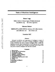
If the robot is facing the speakers then the direction coefficient was found to have a mean value of 0.99. This value fluctuates about this mean value but never goes to far beyond 1. Figure 5.6 shows the graphs which shows the fluctuation of the Direction Coefficient when Both ears were directly in front of he speakers. Five different readings were taken at various distances for a constant loudness of sound.
23
QT: Final Report
Direction Coefficient Values when both ears are facing the sound source
Coefficient value
1.10 1.05 1.00 Series1
0.95
Linear (Series1)
0.90 0.85 0.80 Samples at various increasing distances (1 to 5 Feet)
FIGURE 5.7: DIRECTION COEFFICIENT WHEN BOTH EARS ARE FACING THE SOUND SOURCE
The trend line in the graph shows that the value remains close to 1 for most part of the graph. The last part where is starts going away from 1 is the area where the samples were obtained at 5 Feet or more. This shows that the reliability of the ear falters at this distance, which was pointed out earlier also.
1.60 1.50 1.40 1.30 1.20 1.10 1.00 0.90 0.80
1feet 2feet 3feet
21
19
17
15
13
11
9
7
5
3
4feet
1
Direction Coefficient
Direction Coefficient Value when Left Ear was facing the Sound Source
Samples
FIGURE 5.8: DIRECTION COEFFICIENT WHEN LEFT EAR IS FACING THE SOUND SOURCE
24
QT: Final Report
When samples were taken when the Left ear was facing the sound source the Direction coefficient had values way above 1.10 for the values which were taken at 3 feet or less. However for 4 feet we can see that the results are not accurate and the value drops to 1. This is because the sensitivity of the microphones falls bellow the threshold required for accurately determining the sound source. Another interesting observation is the values obtained for the measurements done at 2 feet. All these values are way above 1.3. This can be explained in the context of the compensation for the saturation effect of the microphones. A saturation threshold of a 100 was set in the code and any value less than this resulted in a maximum possible value of the microphone. When the robot is really close to the sound source the microphones are saturated and hence the values are not as much as when the robot is a distinct from each other as they are when the robot is at say 2 feet when both microphones are working in the maximum possible output range instead of the saturation range.
When the right ear was made to face the sound source a similar pattern was obtained. The robot was able to determine direction reliably if it was close enough to the source. The reliability drops off at distances greater than 3 feet
25
QT: Final Report
Direction Coefficient
Direction Coefficient when right Ear was facing the sound source 1.50 1.40 1.30
1 feet
1.20 1.10
3 feet
2 feet 4 feet
1.00 0.90
5 feet
0.80 Sapmles
FIGURE 5.9: DIRECTION COEFFICIENT WHEN RIGHT EAR IS FACING THE SOUND SOURCE
All values for measurements less than equal to 3 feet are way above 1.1. Here the direction coefficient is defined as DC = Averaged Right Ear Value/ Averaged Left Ear Value The actual determination of the direction can be done by looking at the relative values of the outputs of the two ears. Accuracy of Results: The direction coefficient is therefore proved to be working within a 3 feet range. We can distinguish the direction of a sound using this method very reliably with the range mentioned above.
26
QT: Final Report
6. Home: QT has a special relationship with its home. QT’s home is a cylindrical object which has an Infra red beacon installed in it so that QT can find the home from where ever it is. There are five IR LEDs which are installed in a semi circular fashion on the home cylinder. There LEDs are modulated at 32.78 KHz so that the special Sharp on QT called the Home Detector can find the modulated signal. Modulation Circuitry: A simple 555 based multi-vibrator was used to generate the signal for the modulation. The circuit diagram is given below. 9V DC 470 470
5 IR LEDs
470 470 470 470 8
4
Green LED
1K 7
555
6 22kOhm 1K 2
0.1 UF
3 1
FIGURE 6.1: HOME BEACON CIRCUITARY
The 555 is used in its multi-vibrator mode and the values of the two variable resistors were adjusted until a frequency of 32.78KHz was achieved. A 2N2222 transistor powers the LEDs. Home is powered by a 9V battery.
27
QT: Final Report
7. Behaviors: There are four behaviors programmed in QT. I will describe each here. Explore the Universe This is a pretty straight forward behavior and can be put equivalent to the obstacle avoidance behavior on most of the other robots. QT will determine its course based upon the IR sensors values, Bumps and the CdS cells output. Here is a short algorithm for this behavior. See the exact code in Appendix A. 1. Turn on the IR LEDs and the two front red mode lights 2. If Left IR detector > threshold then Turn right 3. If Right IR detector > threshold then Turn left 4. If front IR detector > threshold then stop, go back and Turn random 5
If front bumper hits something stop, go back and turn random
6
If CdS cell > Table Threshold then stop, go back and turn random. This is to make sure that QT won’t go under tables from where it is very difficult to get it out if it gets into trouble.
QT will continue in this behavior until it either becomes frightened or it becomes dark which is an indication of time to sleep. Fear: This behavior is invoked when either one of the two microphones on QT go into saturation. This indicates are very loud sound in the room. Upon hearing this loud sound QT will work according to the following algorithm.
28
QT: Final Report
1. Rotate 360 degrees and sample the values from the Home detector every 100 msec. Store these values in an array for later use. This is the data acquisition phase. 2. Stop and go through the contents of the array, find and store the maximum value in a variable. 3. Rotate till the maximum value is found. Once found stop and move directly towards this heading. 4. If while trying to find the maximum value no such value is encountered with in 5 seconds then go to the data acquisition phase again and repeat the process. 5. If the home is detected and progress is being made in going towards it then monitor the values from the home detector. If the values start decreasing then it means a drift from the correct course. Go to the data acquisition mode and repeat steps 1 through 4. 6. If Center IR > threshold value then it means you are at home! 7. Once home dance to the music. Dance behavior will be described separately. Steps 1 through 6 constitute the function called “gohome(void)” This function is a general purpose function and is used in the sleep behavior also which I will describe next. Sleep: This behavior is invoked when the value from the CdS cell goes above the threshold value. The algorithm for this behavior is given below 1. If Light > Sleep threshold then stop 2. Turn on the Right Green Mode LED and find home and go there 3. Turn off IRs and all LEDs 29
QT: Final Report
4. Sample the light every second 5. If it is still darkness then remain in the sleep state otherwise get out of this behavior. Dance: When QT reaches home frightened it dances. The dance steps are simple. This behavior makes use of QTs differential Ear. The algorithm goes as follows: 1. Get corrected and averaged samples from both ears as mentioned in the sensor section of this report. 2. If Left ear >= 1.05* Right ear then turn left 180 degrees 3. If Right ear >= 1.05* Left ear then turn right 180 degrees 4. Otherwise go forward for 500ms and come back for 500ms. 5. Repeat steps 1 through 4 till there is a bright light shined on the CdS cell or 30 seconds elapse which every comes first. QT danced to the music of “Duran Duran” and was an interesting sight to watch. One interesting observation while programming this dance routine was the fact that FLOAT qualifier is unavailable in ICC11 which was surprising for me. I tried to make it work but in vain. Then I had to resort to the multiplication with the factor instead. All four behaviors are combined in the code called “Final.C” in Appendix A.
30
QT: Final Report
8. Conclusion and Future Extensions QT is completely functional and it did not disappoint me on the demo day. In general I am very satisfied with what I achieved and am proud of my QT!.
However, the behaviors implemented in QT were somewhat, towards the lower end of what could have been done.
One very important behavior that was not implemented was the self battery monitoring and charging. This was rather an involved behavior, with issues of docking with the Home and then charging circuitry to be resolved. This can be a very exciting addition to QT in the future.
Another important characteristic of a pet is to identify its master. This can again be done using the Home detector and with having some sort of a beacon which the person will wear. An interesting behavior could have been to follow the master.
In future one of the interesting addition can be the addition of another QT to the present one. This will enable them to work together and will be interesting to watch.
31
QT: Final Report
9. References: Anita M Flynn, Bruce A. Seiger Joseph L. Jones. Mobile Robots: Inspiration to Implementation Second Edition. A.K. Peters Ltd. 1998 Fred G. Martin The 6.270 Robot Builder’s Guide Photocopy Fall 1998 Keith L Dotty TJPRO Assembly Manual Mechatronix Inc 1999. Keith L Dotty TJPRO User Manual Mekatronix Inc 1999. Kevin Kelly Out of Control Addison Wesley Publishing Company 1997
10. Sources for Parts: Mekatronics http://www.mekatronix.com/ The Robot Store http://www.robotstore.com/ Radio Shackhttp://www.theshack.com/ http://www.theshack.com/ Archer Road: 352-375-2426 Main Street and NW16th Ave: 352-375-2336 Oaks Mall: 352-331-7217 13th ST and 23rd Ave: 352-373-1396 Skipper Electronics 3911 Newberry Road 352-373-6796 Electronics Plus 2026 SW 34th Street 352-371-3223 The Hobby Shop 3424 W. University Ave. 352-371-1128 Ace Hardware 3727 W. University Ave. 352-378-4650 Lowe's Home Improvement 3500 SW Archer Road 352-376-9900
32
QT: Final Report
Appendix A: Source Codes /*********************************************************************************** * MEKATRONIX Copyright 1998 * Title : final.c * * Programmer : Jawad Khan * * Original code: Keith L. Doty and modified for IC by Scott Jantz * * Date July 28, 1999 * * Version 1 * * Description * * Four behaviors combined: Explore, Sleepy, Fear and dance * ************************************************************************/
/*************************** Includes ********************************/ #include #include /************************ End of Includes ****************************/
/*************************** Constants ********************************/ #define CENTER_IR analog(4) #define LEFT_EAR analog(1) #define RIGHT_EAR analog(5) #define LIGHT analog(6) #define HOME analog(7) #define AVOID_THRESHOLD 115 #define SPEED 45 #define HOME_THRESHOLD 85 #define SLEEP_THRESHOLD 200 #define FEAR_THRESHOLD 45 #define MDGLEFT_ON *(unsigned char *)(0x7000) = 0x87 //turn on left greenmode Lt #define MDRLEFT_ON *(unsigned char *)(0x7000) = 0x47 //turn on left redmode Lt #define MDGRIGHT_ON *(unsigned char *)(0x7000) = 0x27 //turn on right greenmode Lt #define MDRRIGHT_ON *(unsigned char *)(0x7000) = 0x17 //turn on right redmode Lt #define AVOIDANCE_ON *(unsigned char *)(0x7000) = 0x57 //turn on both green mode Lt #define FEAR_ON *(unsigned char *)(0x7000) = 0xA7 //turn both red mode Lt #define SLEEP_ON *(unsigned char *)(0x7000) = 0x87 //turn on left greenmode Lt #define DANCE_ON *(unsigned char *)(0x7000) = 0xF7 //turn on both red and green Lt #define MODE_OFF *(unsigned char *)(0x7000) = 0x07 //turn off mode lights #define ALL_OFF *(unsigned char *)(0x7000) = 0x00 //turn off every light /************************ End of Constants ****************************/
/*************************** Prototypes *********************************/ void turn(void); void avoid(void); 33
QT: Final Report
void gohome(void); void fear(void); void rouk(void); void rotate(void); void sleep(void); int findbeacon(void); int findhome(int); void dance(void); void danceroutine(void); /************************ End of Prototypes *****************************/
void main(void) /****************************** Main ***********************************/ {
init_analog(); init_motorme(); init_clocktjp(); IRE_ON;
/* turn on IR emitters */
START; /*Press the rear bumper to start the program*/ while(1) { avoid(); fear(); sleep();
//so that QT won't go under tables! if (LIGHT>180) { motorme(LEFT_MOTOR, 0); motorme(RIGHT_MOTOR, 0); wait(600); turn(); } wait(35);
} } /**************************** End of Main ******************************/ void turn(void) /************************************************************************ * Function: Will turn in a random direction for a "random" amount of * 34
QT: Final Report
* time, dictated by the fast changine lower bits in * * mseconds(). * Returns: None * * * * Inputs * * Parameters: None * * Globals: None * * Registers: TCNT * * Outputs * * Parameters: None * * Globals: None * * Registers: None * * Functions called: motorme(), wait() * Notes: * ************************************************************************/ { int i; unsigned rand;
*
*
rand = TCNT; if (rand & 0x0001) /*turn left*/ { motorme(RIGHT_MOTOR, SPEED); motorme(LEFT_MOTOR, -SPEED); } else /*turn right*/ { motorme(RIGHT_MOTOR, -SPEED); motorme(LEFT_MOTOR, SPEED); } i=(rand % 1024); if(i>250) wait(i); else wait(250); } /***********************End Function turn ****************************/
void avoid(void) /************************************************************************ * Function: This function implements the basic Collision avoidance * If there is something in front or if front bumper hits * * * something then it will put the robot in reverse * Returns: None * * * * Inputs * * Parameters: None * * Globals: None * * Registers: * 35
*
*
QT: Final Report
* Outputs * * Parameters: None * * Globals: None * * Registers: None * * Functions called: motorme(), wait(), turn() * * Notes: * ************************************************************************/ { int irdr, irdl, speedr, speedl; irdr = RIGHT_IR; irdl = LEFT_IR; AVOIDANCE_ON; if (irdl > AVOID_THRESHOLD) speedr = -SPEED; else speedr = SPEED; if (irdr > AVOID_THRESHOLD) speedl = -SPEED; else speedl = SPEED; motorme(RIGHT_MOTOR, -(speedr)); motorme(LEFT_MOTOR, -(speedl)); /* This "if" statement checks the bumper. If the bumper is pressed, */ /* Tj will back up, and turn. */
if((CENTER_IR > AVOID_THRESHOLD )||(FRONT_BUMP )) { motorme(LEFT_MOTOR, SPEED); motorme(RIGHT_MOTOR, SPEED); wait(200); turn(); } wait(35); } /***********************End Function Avoid ****************************/ void gohome(void) /************************************************************************ * Function: QT will find the home and go there * Returns: None * * * * Inputs * * Parameters: None * * Globals: None * * Registers: TCNT * * Outputs * * Parameters: None * 36
*
QT: Final Report
* Globals: None * * Registers: None * * Functions called: motorme(), wait() * * Notes: * ************************************************************************/ { int speed=40; int j,i,k; int beacon; int initial; int initialtime; int dancetime; int flag; flag=2; while (flag !=1) { beacon = findbeacon(); flag = findhome(beacon); if (flag==1) { while (CENTER_IR < AVOID_THRESHOLD ) { motorme(LEFT_MOTOR, -38); motorme(RIGHT_MOTOR, -38); wait(500);
if (HOME < beacon) { flag=2; break ; } if ((BUMPER > 0) && (BUMPER < 120 )) { rouk(); wait(1000); break ; } } } } rouk(); wait(1000); } /***********************End Function gohome ****************************/
void sleep(void) /************************************************************************ 37
QT: Final Report
* Function: QT will go home and sleep if it finds that it is dark * * QT will remain in its home till it is dark. * * * Returns: None * * * * Inputs * * Parameters: None * * Globals: None * * Registers: None * * Outputs * * Parameters: None * * Globals: None * * Registers: None * * Functions called: rouk(), wait(), gohome(); * * Notes: * ************************************************************************/ {
*
if (LIGHT > SLEEP_THRESHOLD) { SLEEP_ON; rouk(); wait(1000); gohome(); } while (LIGHT > SLEEP_THRESHOLD) { ALL_OFF; rouk(); wait(1000); } AVOIDANCE_ON; } /**************************** End of sleep ******************************/
void danceroutine(void) /************************************************************************ * Function: QT will dance for 2 minutes * * * * * * Returns: None * * Inputs * Parameters: None * Globals: None * Registers: None * Outputs * Parameters: None * Globals: None * Registers: None 38
* * * * * * * * * * QT: Final Report
* Functions called: turn(), dance(); * * Notes: * ************************************************************************/ { int dancetime; dancetime=seconds; while ((LIGHT > 85) && (minutes < dancetime + 30)) { dance(); } wait(5000); turn(); } /**************************** End of function danceroutine ***************/ void fear(void) /************************************************************************ * Function: will detect loud sounds and go home * * Returns: None * * * * Inputs * * Parameters: None * * Globals: None * * Registers: TCNT * * Outputs * * Parameters: None * * Globals: None * * Registers: None * * Functions called: motorme(), wait() * * Notes: * ************************************************************************/ { if ((LEFT_EAR < FEAR_THRESHOLD)||(RIGHT_EAR < FEAR_THRESHOLD)) { FEAR_ON; rouk(); wait(1000); gohome(); danceroutine(); } } /**************************** End of Function Fear **********************/
void rotate(void) /************************************************************************ * Function: QT will spin 360 degrees twice to detect the beacon * Returns: None * * * 39
*
QT: Final Report
* Inputs * * Parameters: None * * Globals: None * * Registers: TCNT * * Outputs * * Parameters: None * * Globals: None * * Registers: None * * Functions called: motorme() * * Notes: * ************************************************************************/ { int turn_speed=32; motorme(LEFT_MOTOR, turn_speed); motorme(RIGHT_MOTOR, -turn_speed); } /**************************** End of Function rotate *******************/
void rouk(void) /************************************************************************ * Function: QT will Stop. Rouk in Urdu means to stop! * Returns: None * * * * Inputs * * Parameters: None * * Globals: None * * Registers: TCNT * * Outputs * * Parameters: None * * Globals: None * * Registers: None * * Functions called: motorme() * * Notes: * ************************************************************************/
*
{ motorme(LEFT_MOTOR, 0); motorme(RIGHT_MOTOR, 0); } /**************************** End of Function rouk *******************/ int findbeacon(void) /************************************************************************ * Function: QT will rotate and try to find the largest value of the * * Home beacon. This function will return that value. * * * 40
QT: Final Report
* Returns: int which is the larges value of the home beacon * * Inputs * * Parameters: None * * Globals: None * * Registers: None * * Outputs * * Parameters: None * * Globals: None * * Registers: None * * Functions called: rouk(),rotate(),wait(); * * Notes: * ************************************************************************/ { int i,k,initial,beacon1; int homereadings[20];
*
rotate(); for ( i=0; i (initialtime + 5)) break;
if (HOME == beacon ) { found =1; rouk(); wait(500); } } return found; } /**************************** End of Function findhome *******************/ void dance(void) /************************************************************************ * Function: QT will try to dance on music. It will rotate if to the * * opp direction of the source of sound. If the source * * is directly infront of it then it will just go forward * * come back. This is the main fucntion for sampling the * * sound also. * * Plus both the microphones are also calibrated in this * * function so that the output from both be comparable * * * * Returns: int is the measure of whether it found home or not * * * Inputs * * Parameters: None * * Globals: None * * Registers: None * * Outputs * * Parameters: None * * Globals: None * 42
QT: Final Report
* Registers: None * * Functions called: rouk(),rotate(),wait(); * * Notes: * ************************************************************************/
{ int i; int j; volatile int test_left; volatile int test_right; volatile unsigned int right ; volatile unsigned int left; volatile unsigned int rightavg ; volatile unsigned int leftavg; float coeff[2]; float L; float R; left=0; right=0; leftavg=0; rightavg=0; for ( j=1; j